
Operation Manual
Page 2
... Connection 34 -i- TABLE OF CONTENTS GENERAL DESCRIPTION 1 1. Introduction 1 2. Counting the Parts 3 3. Paper Loading 10 6.1. Power Connection 15 INSTALLATION OF MX-80 F/T TYPE II 17 1. Repacking steps 17 2. Removal of the Printer 18 4. Fanfold paper 25 7.1.1. Unpacking 17 1.1. Installation of fanfold paper 13 6.3. Separator Installation 23 6. Dismounting of roll paper 29 7.3. Loading of Tractor...
... Connection 34 -i- TABLE OF CONTENTS GENERAL DESCRIPTION 1 1. Introduction 1 2. Counting the Parts 3 3. Paper Loading 10 6.1. Power Connection 15 INSTALLATION OF MX-80 F/T TYPE II 17 1. Repacking steps 17 2. Removal of the Printer 18 4. Fanfold paper 25 7.1.1. Unpacking 17 1.1. Installation of fanfold paper 13 6.3. Separator Installation 23 6. Dismounting of roll paper 29 7.3. Loading of Tractor...
Operation Manual
Page 3
Indicators 37 1.3. Setting of MX-80 Type II and MX-80 F/T Type II 83 2. Character designation codes 63 3.4. Control Codes in the Text Mode 56 3.1. Construction of DIP switch N O. 2 46 5.3. ASCII Code Table 91 4. Printer initial check 38 2. Self-Test 4 0 5. Setting of DIP switch No. 1 4 5 5.2. H o w t o o b t a i n...4.1. Switches 36 1.2. Setting sequence of Some Terms Often Used 54 3. Definitions of functional specifications 4 8 WHAT IS THE MX-80 TYPE II 52 1. Relationship between data and dot wires 71 4 . 4 . Parallel Interface 87 3. Buzzer 39 3....
Indicators 37 1.3. Setting of MX-80 Type II and MX-80 F/T Type II 83 2. Character designation codes 63 3.4. Control Codes in the Text Mode 56 3.1. Construction of DIP switch N O. 2 46 5.3. ASCII Code Table 91 4. Printer initial check 38 2. Self-Test 4 0 5. Setting of DIP switch No. 1 4 5 5.2. H o w t o o b t a i n...4.1. Switches 36 1.2. Setting sequence of Some Terms Often Used 54 3. Definitions of functional specifications 4 8 WHAT IS THE MX-80 TYPE II 52 1. Relationship between data and dot wires 71 4 . 4 . Parallel Interface 87 3. Buzzer 39 3....

Operation Manual
Page 4
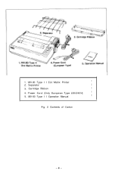
LIST OF FIGURES Fig. 1 EPSON MX-80 Type II and MX-80 F/T Type II Dot Matrix Printers ... 1 Fig. 2 Contents of Carton 4 Fig. 3 Laying Printer on Firm Surface 5 Fig. 4 Assembly Tools 6 Fig. 5 Removal of Shipping Screws 7 Fig. 6 Removal of Printer Lid 7 Fig. 7 Remounting of Printer Lid 8 Fig. 8 Cartridge Ribbon Setting 8 Fig. 9 Cartridge Ribbon Setting ...Fig. 31 Raising of Sprocket Lock Levers 26 Fig. 32 Engagement of Paper Feed Holes on Feeding Pins 26 Fig. 33 Printer with Fanfold Paper Set Completely 27 Fig. 34 Example of Paper Arrangement 27 Fig. 35 Top of Form Position Setting 28 ...
LIST OF FIGURES Fig. 1 EPSON MX-80 Type II and MX-80 F/T Type II Dot Matrix Printers ... 1 Fig. 2 Contents of Carton 4 Fig. 3 Laying Printer on Firm Surface 5 Fig. 4 Assembly Tools 6 Fig. 5 Removal of Shipping Screws 7 Fig. 6 Removal of Printer Lid 7 Fig. 7 Remounting of Printer Lid 8 Fig. 8 Cartridge Ribbon Setting 8 Fig. 9 Cartridge Ribbon Setting ...Fig. 31 Raising of Sprocket Lock Levers 26 Fig. 32 Engagement of Paper Feed Holes on Feeding Pins 26 Fig. 33 Printer with Fanfold Paper Set Completely 27 Fig. 34 Example of Paper Arrangement 27 Fig. 35 Top of Form Position Setting 28 ...

Operation Manual
Page 5
...Fig. 43 Print Area 3 2 Fig. 44 Setting of Cut Paper Sheet 33 Fig. 45 Printer with Cut Paper Sheet Set Completely 33 Fig. 46 Gap Adjustment 35 Fig. 47 Switches and Indicators on Control ...Panel 36 Fig. 48 Printer Initial Check 38 Fig. 49 Flowchart of Paper Out Status Release Procedure 39 Fig. 50 Removing Manual... All 4 Screws 41 Fig. 52 Pulling Out Wires Hooked to Control Panel 42 Fig. 53 Construction of Type II Printer 43 Fig. 54 Location of DIP Switches 4 4 Fig. 55 Setting DIP Switches 4 4 Fig. 56 Setting Amount...
...Fig. 43 Print Area 3 2 Fig. 44 Setting of Cut Paper Sheet 33 Fig. 45 Printer with Cut Paper Sheet Set Completely 33 Fig. 46 Gap Adjustment 35 Fig. 47 Switches and Indicators on Control ...Panel 36 Fig. 48 Printer Initial Check 38 Fig. 49 Flowchart of Paper Out Status Release Procedure 39 Fig. 50 Removing Manual... All 4 Screws 41 Fig. 52 Pulling Out Wires Hooked to Control Panel 42 Fig. 53 Construction of Type II Printer 43 Fig. 54 Location of DIP Switches 4 4 Fig. 55 Setting DIP Switches 4 4 Fig. 56 Setting Amount...
Operation Manual
Page 7
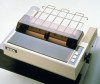
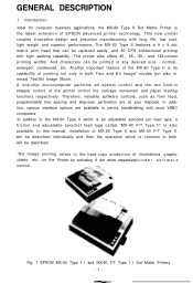
... MX-80 Type II which is the latest extension of the MX-80 Type II is also available. The MX-80 Type II features a 9 x 9 dot matrix print head that can be replaced easily, and 80 CPS bidirectional printing with logic seeking capability. In addition, various interface options are at your disposal. Fig. 1 EPSON MX-80 Type I I and MX-80 F/T Type I I Dot Matrix Printers...
... MX-80 Type II which is the latest extension of the MX-80 Type II is also available. The MX-80 Type II features a 9 x 9 dot matrix print head that can be replaced easily, and 80 CPS bidirectional printing with logic seeking capability. In addition, various interface options are at your disposal. Fig. 1 EPSON MX-80 Type I I and MX-80 F/T Type I I Dot Matrix Printers...

Operation Manual
Page 8
Characteristics The MX-80 Type II and MX-80 F/T Type II have been designed as a printer with versatile functions to meet various business applications (a) Top of their major characteristics. (1) Both text printing for general data.... (b) Skip-over function selectable by DIP switch setting or variable by software. (c) Programmable line spacing. (d) Vertical tabulation and horizontal tabulation (e) Buzzer, printer select/deselect function. (4) High throughput by DIP switch setting or software. (7) Complete with standard equipment including paper end detector, custom cartridge ribbon, etc....
Characteristics The MX-80 Type II and MX-80 F/T Type II have been designed as a printer with versatile functions to meet various business applications (a) Top of their major characteristics. (1) Both text printing for general data.... (b) Skip-over function selectable by DIP switch setting or variable by software. (c) Programmable line spacing. (d) Vertical tabulation and horizontal tabulation (e) Buzzer, printer select/deselect function. (4) High throughput by DIP switch setting or software. (7) Complete with standard equipment including paper end detector, custom cartridge ribbon, etc....
Operation Manual
Page 9
... Repacking can be saved for evidence of shipping damage or mishandling. Place the Printer with the packing material attached. STEP 2. STEP 6. Take off the packing material carefully. Counting the Parts The MX-80 Type II and standard accessories are as follows: STEP 1. Unpacking steps Unpacking... such evidence is recommended that all original packing materials be carried out by following the above steps in Fig. 2. Unpacking Before removing the MX-80 Type I I as soon as shown in the reverse order. (Repacking: Shipment for repair, storage, etc.) NOTE: It is present,...
... Repacking can be saved for evidence of shipping damage or mishandling. Place the Printer with the packing material attached. STEP 2. STEP 6. Take off the packing material carefully. Counting the Parts The MX-80 Type II and standard accessories are as follows: STEP 1. Unpacking steps Unpacking... such evidence is recommended that all original packing materials be carried out by following the above steps in Fig. 2. Unpacking Before removing the MX-80 Type I I as soon as shown in the reverse order. (Repacking: Shipment for repair, storage, etc.) NOTE: It is present,...
Operation Manual
Page 10
Separator 1 3. Cartridge Ribbon 1 4. Power Cord (Only European Type 220/240V) 1 5. MX-80 Type I I Dot Matrix Printer 1 2. 1. MX-80 Type I I Operation Manual 1 Fig. 2 Contents of Carton -4-
Separator 1 3. Cartridge Ribbon 1 4. Power Cord (Only European Type 220/240V) 1 5. MX-80 Type I I Dot Matrix Printer 1 2. 1. MX-80 Type I I Operation Manual 1 Fig. 2 Contents of Carton -4-

Operation Manual
Page 11
...extreme shock. (e) Avoid use of the Printer in humid locations or in the vicinity of greasy dust exists in the air. NOTE: Greasy dust may look like Fig. 3. CRT Display Fig. 3 Laying Printer on which the MX-80 Type I I is placed. (b) Avoid operating the MX-80 Type I I , observe the following... instructions. (a) Place the Printer on a bench, tabletop or any other convenient flat surface with enough room for the ...
...extreme shock. (e) Avoid use of the Printer in humid locations or in the vicinity of greasy dust exists in the air. NOTE: Greasy dust may look like Fig. 3. CRT Display Fig. 3 Laying Printer on which the MX-80 Type I I is placed. (b) Avoid operating the MX-80 Type I I , observe the following... instructions. (a) Place the Printer on a bench, tabletop or any other convenient flat surface with enough room for the ...

Operation Manual
Page 12
... Fig. 5.) STEP 1. (2) Removal of protective paper for paper end detector The MX-80 Type II is provided with a screwdriver, the two shipping screws visible on its left side. Stand the printer on the underside of the shipping screws is to be reshipped, remember to return...transportation. Phillips Type Fig. 4 Assembly Tools (4) Removal of shipping screws The purpose of the lower case. -6- If the MX-80 Type II is to disassemble or assemble the printer. (1) Phillips type screwdriver 1 pc. (2) Round-blade type screwdriver 1 pc. Remove with a protective paper inserted between ...
... Fig. 5.) STEP 1. (2) Removal of protective paper for paper end detector The MX-80 Type II is provided with a screwdriver, the two shipping screws visible on its left side. Stand the printer on the underside of the shipping screws is to be reshipped, remember to return...transportation. Phillips Type Fig. 4 Assembly Tools (4) Removal of shipping screws The purpose of the lower case. -6- If the MX-80 Type II is to disassemble or assemble the printer. (1) Phillips type screwdriver 1 pc. (2) Round-blade type screwdriver 1 pc. Remove with a protective paper inserted between ...
Operation Manual
Page 13
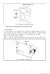
Rough or careless handling of Printer Lid -7- Stand the printer lid upright. Push the printer lid toward the right and pull up its hinges. STEP 1. STEP 2. Right Side of the Printer Fig. 5 Removal of Shipping Screws NOTE: Save the two shipping screws for possible future use. < SUPPLEMENT > l If the printer lid is an obstacle when removing the shipping screws, be sure to , or even breakage of, its left side. (See Fig. 6.) Fig. 6 Removal of the printer lid may result in damage to take off the printer lid by observing the following steps.
Rough or careless handling of Printer Lid -7- Stand the printer lid upright. Push the printer lid toward the right and pull up its hinges. STEP 1. STEP 2. Right Side of the Printer Fig. 5 Removal of Shipping Screws NOTE: Save the two shipping screws for possible future use. < SUPPLEMENT > l If the printer lid is an obstacle when removing the shipping screws, be sure to , or even breakage of, its left side. (See Fig. 6.) Fig. 6 Removal of the printer lid may result in damage to take off the printer lid by observing the following steps.
Operation Manual
Page 14
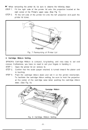
... the cartridge ribbon down , Fig. 7 Remounting of the printer lid onto the left projection and push the printer lid down . (See Fig. 8.) Fig. 8 Cartridge Ribbon Setting -8- Fit the left side of Printer Lid 4. Open the printer lid (or remove it . STEP 3. To facilitate the cartridge... ribbon setting, be sure to soil your fingers in handling it ). STEP 2. Push the cartridge ribbon down and set and remove. Cartridge Ribbon Setting EPSON's Cartridge Ribbon is touching.
... the cartridge ribbon down , Fig. 7 Remounting of the printer lid onto the left projection and push the printer lid down . (See Fig. 8.) Fig. 8 Cartridge Ribbon Setting -8- Fit the left side of Printer Lid 4. Open the printer lid (or remove it . STEP 3. To facilitate the cartridge... ribbon setting, be sure to soil your fingers in handling it ). STEP 2. Push the cartridge ribbon down and set and remove. Cartridge Ribbon Setting EPSON's Cartridge Ribbon is touching.
Operation Manual
Page 16
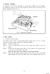
... center of the shaft. STEP 4. Raise the printer lid. Loading of the Printer contributes to insert the fanfold paper between the frame and plastic roller of the printer mechanism. (See Fig. 11.) Fig. 11 Separator Installation 6. Separator Installation The separator of fanfold paper The MX-80 Type II Printer accommodates fanfold paper from the platen. If...
... center of the shaft. STEP 4. Raise the printer lid. Loading of the Printer contributes to insert the fanfold paper between the frame and plastic roller of the printer mechanism. (See Fig. 11.) Fig. 11 Separator Installation 6. Separator Installation The separator of fanfold paper The MX-80 Type II Printer accommodates fanfold paper from the platen. If...
Operation Manual
Page 17
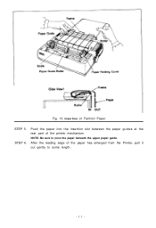
After the leading edge of the paper has emerged from the Printer, pull it out gently to pass the paper beneath the upper paper guide. STEP 6. Push the paper into the insertion slot between the paper guides at the rear part of Fanfold Paper STEP 5. NOTE: Be sure to some length. -ll- Fig. 12 Insertion of the printer mechanism.
After the leading edge of the paper has emerged from the Printer, pull it out gently to pass the paper beneath the upper paper guide. STEP 6. Push the paper into the insertion slot between the paper guides at the rear part of Fanfold Paper STEP 5. NOTE: Be sure to some length. -ll- Fig. 12 Insertion of the printer mechanism.

Operation Manual
Page 19
...button. (Details are described later.) -13- NOTE: Do not attempt to pull out the paper in an accordion style. Fig. 15 Printer with Fanfold Paper Set Completely NOTE: When the MX-80 Type II is to be used on a desk or a bench, arrangement of the fanfold paper in parallel with the... MX-80 Type II as shown below . (1) To disengage the paper from the paper holding mechanism, pull it forward out of Paper Arrangement 6.2. For this, turn the Power Switch on the Printer. Removal of fanfold paper To remove the fanfold paper, ...
...button. (Details are described later.) -13- NOTE: Do not attempt to pull out the paper in an accordion style. Fig. 15 Printer with Fanfold Paper Set Completely NOTE: When the MX-80 Type II is to be used on a desk or a bench, arrangement of the fanfold paper in parallel with the... MX-80 Type II as shown below . (1) To disengage the paper from the paper holding mechanism, pull it forward out of Paper Arrangement 6.2. For this, turn the Power Switch on the Printer. Removal of fanfold paper To remove the fanfold paper, ...
Operation Manual
Page 20
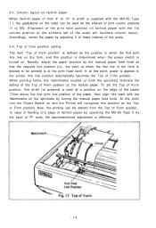
..., and this point, power is effective. -14- If, at the print head level. In case of feeding one page of fanfold paper by operating the MX-80 Type II by turning the manual paper feed knob. To set the Top of Form position, first enter (or preprint) a mark at a position on the... the sprockets facilitate the setting of the Top of Form position. Namely, adjust the paper position by adjusting it to the printer, this mark with the matchmarks on fanfold paper with the MX-80 Type I I, the graduations on . 6.3. Now, the printing can be used as the Top of Form position on and the...
..., and this point, power is effective. -14- If, at the print head level. In case of feeding one page of fanfold paper by operating the MX-80 Type II by turning the manual paper feed knob. To set the Top of Form position, first enter (or preprint) a mark at a position on the... the sprockets facilitate the setting of the Top of Form position. Namely, adjust the paper position by adjusting it to the printer, this mark with the matchmarks on fanfold paper with the MX-80 Type I I, the graduations on . 6.3. Now, the printing can be used as the Top of Form position on and the...

Operation Manual
Page 21
... different from the label located on the chassis at the rear of paper to the Printer, "Initialization" will take place in the Printer with the correct AC rating from the store where you purchased the MX-80 Type I I. -15- Please obtain a replacement unit with the effects described in ... 18.) Forward: To widen gap. Set the lever to the 7th step. (3) Should printed characters become faint due to operate the Printer. Power Connection The EPSON MX-80 Type II Dot Matrix Printer is capable of operating on the left frame of carbon paper sheets is used . 7. Backward: To narrow gap.
... different from the label located on the chassis at the rear of paper to the Printer, "Initialization" will take place in the Printer with the correct AC rating from the store where you purchased the MX-80 Type I I. -15- Please obtain a replacement unit with the effects described in ... 18.) Forward: To widen gap. Set the lever to the 7th step. (3) Should printed characters become faint due to operate the Printer. Power Connection The EPSON MX-80 Type II Dot Matrix Printer is capable of operating on the left frame of carbon paper sheets is used . 7. Backward: To narrow gap.
Operation Manual
Page 23
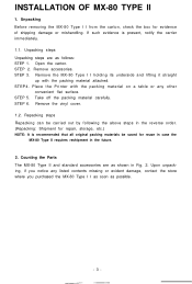
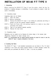
... box for repair, storage, etc.) NOTE: It is present, notify the carrier immediately. 1.1. Place the Printer with the packing material attached. Counting the Parts The MX-80 F/T Type I I as soon as follows: STEP 1. If such evidence is recommended that all original packing... 3. STEP 4. Take off the packing material carefully. Remove the vinyl cover. 1.2. INSTALLATION OF MX-80 F/T TYPE II 1. Unpacking steps Unpacking steps are as shown in the future. 2. Remove the MX-80 F/T Type I I requires reshipment in Fig. 19. STEP 6. Repacking steps Repacking can be saved...
... box for repair, storage, etc.) NOTE: It is present, notify the carrier immediately. 1.1. Place the Printer with the packing material attached. Counting the Parts The MX-80 F/T Type I I as soon as follows: STEP 1. If such evidence is recommended that all original packing... 3. STEP 4. Take off the packing material carefully. Remove the vinyl cover. 1.2. INSTALLATION OF MX-80 F/T TYPE II 1. Unpacking steps Unpacking steps are as shown in the future. 2. Remove the MX-80 F/T Type I I requires reshipment in Fig. 19. STEP 6. Repacking steps Repacking can be saved...

Operation Manual
Page 24
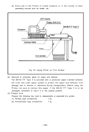
... or above 35°C (95°F) during operation, to sudden changes in the air. 1. MX-80 F/T Type II Dot Matrix Printer 1 2. Installation of the Printer (1) Operating site selection When installing the MX-80 F/T Type I I in places where it may be exposed to prevent the marring of the surface.../24OV) 1 5. NOTE: Rubber feet are provided to direct sunlight or where a great deal of the Printer. Separator 1 3. Your layout may cause the malfunction of Carton 3. MX-80 F/T Type I I is placed. (b) Avoid operating the MX-80 F/T Type. NOTE: Greasy dust may look like Fig. 20.
... or above 35°C (95°F) during operation, to sudden changes in the air. 1. MX-80 F/T Type II Dot Matrix Printer 1 2. Installation of the Printer (1) Operating site selection When installing the MX-80 F/T Type I I in places where it may be exposed to prevent the marring of the surface.../24OV) 1 5. NOTE: Rubber feet are provided to direct sunlight or where a great deal of the Printer. Separator 1 3. Your layout may cause the malfunction of Carton 3. MX-80 F/T Type I I is placed. (b) Avoid operating the MX-80 F/T Type. NOTE: Greasy dust may look like Fig. 20.
Operation Manual
Page 25
...to shocks or vibrations during transportation. (e) Avoid use of the Printer in humid locations or in the vicinity of protective paper for paper end detector The MX-80 F/T Type II is to be sure to disassemble or assemble the printer. (1) Phillips type screwdriver 1 pc. (2) Round-blade type ...screwdriver 1 pc. -19- Before using the Printer, be reshipped, remember to return it to the original...
...to shocks or vibrations during transportation. (e) Avoid use of the Printer in humid locations or in the vicinity of protective paper for paper end detector The MX-80 F/T Type II is to be sure to disassemble or assemble the printer. (1) Phillips type screwdriver 1 pc. (2) Round-blade type ...screwdriver 1 pc. -19- Before using the Printer, be reshipped, remember to return it to the original...


