Product Information Guide
Page 4
... software. DFX - 5000 DOT - This stand provides a catch bin and a paper supply shelf large enough to the fact that do not have an FX driver should work properly if LX, RX, MX, or Epson drivers are routed away from both the front and rear tractors, as well as detents, which hold the printer securely in place. MATRIX PRINTER Installation...
... software. DFX - 5000 DOT - This stand provides a catch bin and a paper supply shelf large enough to the fact that do not have an FX driver should work properly if LX, RX, MX, or Epson drivers are routed away from both the front and rear tractors, as well as detents, which hold the printer securely in place. MATRIX PRINTER Installation...
Service Manual
Page 9
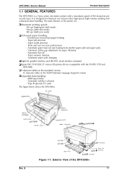
...dot matrix printer with the FX-870/1170 and DFX-5000) D 9 character tables in the standard version 21 character tables in the NLSP (National Language Support) version Cl Upgraded data handling: - 20KB input buffer - Paper memory function - Automatic interface selection - Exterior View of the printer ...bit parallel interface and RS-232C serial interface standard Cl Epson ESC/P-83 (ESC/P version 83) printer driver (compatible with a maximum speed of 560 characters per second (ips) paper feeding - The main features of the DFX-5000+ 1-1 too cover "'"'"'"" 'NV' control panel poper ...
...dot matrix printer with the FX-870/1170 and DFX-5000) D 9 character tables in the standard version 21 character tables in the NLSP (National Language Support) version Cl Upgraded data handling: - 20KB input buffer - Paper memory function - Automatic interface selection - Exterior View of the printer ...bit parallel interface and RS-232C serial interface standard Cl Epson ESC/P-83 (ESC/P version 83) printer driver (compatible with a maximum speed of 560 characters per second (ips) paper feeding - The main features of the DFX-5000+ 1-1 too cover "'"'"'"" 'NV' control panel poper ...
Service Manual
Page 40
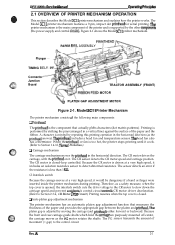
... a hand or finger were inserted inside the printer mechanism during printing. LI Auto platen gap adjustment mechanism The printer mechanism has an automatic platen gap adjustment function that actually pMts characters (dot matrix patterns). The platen gap is performed by moving...between the platen and printhead. DFx-5tW(h Sewka Manual Oparathg Prfncipka 2.1 OVERVIEW OF PRINTER MECHANISM OPERATION This section describes the Model 3C11 printer mechanism and explains how the printer works. Model 3C11 Printer Mechanism The printer mechanism consists of the printer and is less than 1 ...
... a hand or finger were inserted inside the printer mechanism during printing. LI Auto platen gap adjustment mechanism The printer mechanism has an automatic platen gap adjustment function that actually pMts characters (dot matrix patterns). The platen gap is performed by moving...between the platen and printhead. DFx-5tW(h Sewka Manual Oparathg Prfncipka 2.1 OVERVIEW OF PRINTER MECHANISM OPERATION This section describes the Model 3C11 printer mechanism and explains how the printer works. Model 3C11 Printer Mechanism The printer mechanism consists of the printer and is less than 1 ...

Service Manual
Page 52
...cannot recover for the C117 power supply board assembly depend on the C117 MAIN board assembly. 'This procedure is supplied to the printhead drivers on the board type (120 V C117 MB or 220/240 V C117 PSE). the other +35 VDC line supplies power to ...printer has exceeded its duty cycle (the printhead temperature is divided into two sections.) One +35 VDC line supplies power to six of the circuit components, and is located under the carnage motor so that is turned off. The fan lowers the temperature of the nine printhead pins (pins 1,3,5, 7,8, and 9); e m %i;' DFX-5000...
...cannot recover for the C117 power supply board assembly depend on the C117 MAIN board assembly. 'This procedure is supplied to the printhead drivers on the board type (120 V C117 MB or 220/240 V C117 PSE). the other +35 VDC line supplies power to ...printer has exceeded its duty cycle (the printhead temperature is divided into two sections.) One +35 VDC line supplies power to six of the circuit components, and is located under the carnage motor so that is turned off. The fan lowers the temperature of the nine printhead pins (pins 1,3,5, 7,8, and 9); e m %i;' DFX-5000...
Service Manual
Page 53
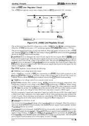
...a +5 V line. When the power supply board receives this control circuit. Cl Printhead driver detection circuit This circuit prevents printhead damage when a printhead driver is a starting resistor. When the printer is damaged, the C117 MAIN board assembly sends the DRERR signal to the power supply board... (HIGH DRERR signal) to the C117 power supply board assembly. This switching procedure monitors the Cl and C2 ports. Operating Principles DFX-5000+ Service Manual 2.2.2 +5 VDC Line Regulator Circuit The +5 VDC line regulator circuit uses a ringing choke coil (RCC) system DC...
...a +5 V line. When the power supply board receives this control circuit. Cl Printhead driver detection circuit This circuit prevents printhead damage when a printhead driver is a starting resistor. When the printer is damaged, the C117 MAIN board assembly sends the DRERR signal to the power supply board... (HIGH DRERR signal) to the C117 power supply board assembly. This switching procedure monitors the Cl and C2 ports. Operating Principles DFX-5000+ Service Manual 2.2.2 +5 VDC Line Regulator Circuit The +5 VDC line regulator circuit uses a ringing choke coil (RCC) system DC...
Service Manual
Page 58
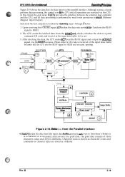
... external heat computer and the CPU, and all operations are stored as character codes and commands or character types are executed via the CPU. AHribute T Printer Mechanism Driver o8 + Character Generator I d4 Command Analyzer el- E05A87 (IC7) CPU (ICI) PS-RAM (IC3) a, .:$ STROBE 1 2 Input Data 40 o Buffer DATA...% checks whether the data is a print command (CR code), and stores it in the input data buffer if it to HIGH. 2. DFX-5000+ Servics Mimml 0per8thg Ffinchl&e Figure 2-19 shows the data flow for data input via the MMIO accesses. Image Buffer I I ?1 I ...
... external heat computer and the CPU, and all operations are stored as character codes and commands or character types are executed via the CPU. AHribute T Printer Mechanism Driver o8 + Character Generator I d4 Command Analyzer el- E05A87 (IC7) CPU (ICI) PS-RAM (IC3) a, .:$ STROBE 1 2 Input Data 40 o Buffer DATA...% checks whether the data is a print command (CR code), and stores it in the input data buffer if it to HIGH. 2. DFX-5000+ Servics Mimml 0per8thg Ffinchl&e Figure 2-19 shows the data flow for data input via the MMIO accesses. Image Buffer I I ?1 I ...
Service Manual
Page 66
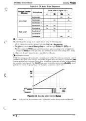
... constant using the following steps: 1. SPl Note: o MYxleratiofl B r decderaiion 2 Figure 2-24. The printer can print while the carriage is labeled A and the driving modes are labeled B. s%? \t . . Acceleration... A, B, and C output the drive signal for the CR motor. Rev. SFlet , . DFX-5000+ Service Manual Table 2-5. The CPU outputs the PWM (pulse width modulation) signal according to the...timing. 4. CR Motor Drive Sequence Operating Pdncipbs Carria#~T~;sfer Driving Mode Driver (Refer to thegatearray. 2. Thegate array selects oneofthe twopulses and sends the...
... constant using the following steps: 1. SPl Note: o MYxleratiofl B r decderaiion 2 Figure 2-24. The printer can print while the carriage is labeled A and the driving modes are labeled B. s%? \t . . Acceleration... A, B, and C output the drive signal for the CR motor. Rev. SFlet , . DFX-5000+ Service Manual Table 2-5. The CPU outputs the PWM (pulse width modulation) signal according to the...timing. 4. CR Motor Drive Sequence Operating Pdncipbs Carria#~T~;sfer Driving Mode Driver (Refer to thegatearray. 2. Thegate array selects oneofthe twopulses and sends the...
Service Manual
Page 67
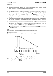
... the encoder signal, when the carriage speed reaches SP1, it uses Deceleration driving mode 2. (Refer to the next sequence (SP1 - The DFX-5000+ printer has a table programmed into ten sections, plus Dutymin. Duty data is divided into its main program ROM to accelerate. 2. D When the... is the largest, and Dutyti represents the minimum duty data for acceleration control. Pulse width modulation (PWM) determines each section, the carriage motor driver is labeled A and the driving modes are labeled B. 1,2, and 3 indicate the PWM control section number. 2-28 Rev. SP2 - When ...
... the encoder signal, when the carriage speed reaches SP1, it uses Deceleration driving mode 2. (Refer to the next sequence (SP1 - The DFX-5000+ printer has a table programmed into ten sections, plus Dutymin. Duty data is divided into its main program ROM to accelerate. 2. D When the... is the largest, and Dutyti represents the minimum duty data for acceleration control. Pulse width modulation (PWM) determines each section, the carriage motor driver is labeled A and the driving modes are labeled B. 1,2, and 3 indicate the PWM control section number. 2-28 Rev. SP2 - When ...
Service Manual
Page 79
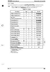
DFX-5000+ Service Manual Disassembly and Assembly 3.1.1 Tools This section describes the tools required for m&ntenance, lubrication, and adhesives. - Phillips screwdriver No. 2 0 A B743800200 Phillips screwdriver No. 1 0 A B7438OO1OO Box driver (7 mm or .28 inches across) o A ... screwdriver (Phillips head, toque adjustable) 0 B - Tools Tool Name Type class Part No. C 34 Table 3-1. O: Commeraally available E: EPSON exclusive A: Mandatory B: Recommended f..... ' Rev. Note: Refer to Chapter 4 for adjustment tools, Chapter 5 for troubleshooting tools, and Chapter...
DFX-5000+ Service Manual Disassembly and Assembly 3.1.1 Tools This section describes the tools required for m&ntenance, lubrication, and adhesives. - Phillips screwdriver No. 2 0 A B743800200 Phillips screwdriver No. 1 0 A B7438OO1OO Box driver (7 mm or .28 inches across) o A ... screwdriver (Phillips head, toque adjustable) 0 B - Tools Tool Name Type class Part No. C 34 Table 3-1. O: Commeraally available E: EPSON exclusive A: Mandatory B: Recommended f..... ' Rev. Note: Refer to Chapter 4 for adjustment tools, Chapter 5 for troubleshooting tools, and Chapter...
Service Manual
Page 138
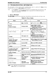
... detected. Rev. Incorrect RAM Q Incorrect RAM is incorrect. Head driver circuit short QThe printhead driver IC is broken. t2The PG motor is shotied. DFX-5000+ Service Manual Troubleshooting 5.1 TROUBLESHOOTING INFORMATION The information in this printer; Some component-level troubleshooting may require an oscilloscope. 5.1.1 Error Messages The DFX-5000+ indicates errors using beeps. Illegal paper memow g lncorr~ paper...
... detected. Rev. Incorrect RAM Q Incorrect RAM is incorrect. Head driver circuit short QThe printhead driver IC is broken. t2The PG motor is shotied. DFX-5000+ Service Manual Troubleshooting 5.1 TROUBLESHOOTING INFORMATION The information in this printer; Some component-level troubleshooting may require an oscilloscope. 5.1.1 Error Messages The DFX-5000+ indicates errors using beeps. Illegal paper memow g lncorr~ paper...
Service Manual
Page 150
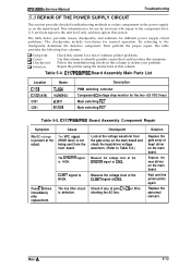
... problem. C117 PSB/PSE Board Assembly Component Repair Symptom No DC voltage is present at CN3. Replace the head driver on the main board. Wait until the printer prints again. The table below provides causes, checkpoints, and solutions for different power supply circuit problems. The checkpoints...the voltage level of pins C1-C6 or RI is not being sent from the gate array on the main board. A 5-13 DFX-5000+ Service Manual Troubleshooting 5.3 REPAIR OF THE POWER SUPPLY CIRCUIT This section provides detailed troubleshooting methods to isolate components in the power supply ...
... problem. C117 PSB/PSE Board Assembly Component Repair Symptom No DC voltage is present at CN3. Replace the head driver on the main board. Wait until the printer prints again. The table below provides causes, checkpoints, and solutions for different power supply circuit problems. The checkpoints...the voltage level of pins C1-C6 or RI is not being sent from the gate array on the main board. A 5-13 DFX-5000+ Service Manual Troubleshooting 5.3 REPAIR OF THE POWER SUPPLY CIRCUIT This section provides detailed troubleshooting methods to isolate components in the power supply ...
Service Manual
Page 154
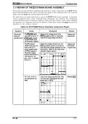
...air the board as described in the C117 MAIN board. CI17 MAIN Board Assembly Component Repair Symptom The printer does not operate at CN1 or check the head driver IC'S voltage waveform. A 5-17 servicers repair to the unit leveI only, and may be defective.... IC9). I 3LY>=J ,66s i A r-000s 1 I Solution Replace the head driver. m ,92V d V24 ,80V SAVE Replace IC9. 4n- - ~ m f" * PE Rev. The reset circuit is for the head driver. (Refer to the component level. DFX-5000+ Service Manual Troubleshooting 5.4 REPAIR OF THE C117 MAIN BOARD ASSEMBLY This section provides detailed...
...air the board as described in the C117 MAIN board. CI17 MAIN Board Assembly Component Repair Symptom The printer does not operate at CN1 or check the head driver IC'S voltage waveform. A 5-17 servicers repair to the unit leveI only, and may be defective.... IC9). I 3LY>=J ,66s i A r-000s 1 I Solution Replace the head driver. m ,92V d V24 ,80V SAVE Replace IC9. 4n- - ~ m f" * PE Rev. The reset circuit is for the head driver. (Refer to the component level. DFX-5000+ Service Manual Troubleshooting 5.4 REPAIR OF THE C117 MAIN BOARD ASSEMBLY This section provides detailed...
Service Manual
Page 162
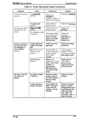
...it feeds the ribbon normally. Print density differs at the same time. Printing is defective. Rev. DFX-5000+ Service Manual Troubleshooting Table 5-7. Printer Mechanism Repair (continued) Symptom A particular dot does not print. Check backlash between PF motor pinion gear and paper feed reduction gear. The ribbon... ribbon driving gear rotates when the cartridge is defective. The PF motor is approximately 2.85 ohms.) Also check the PF motor drivers. Remove the ribbon cartridge, rotate it, and check whether it correctly. Foreign objects are bad, replace main board at the ...
...it feeds the ribbon normally. Print density differs at the same time. Printing is defective. Rev. DFX-5000+ Service Manual Troubleshooting Table 5-7. Printer Mechanism Repair (continued) Symptom A particular dot does not print. Check backlash between PF motor pinion gear and paper feed reduction gear. The ribbon... ribbon driving gear rotates when the cartridge is defective. The PF motor is approximately 2.85 ohms.) Also check the PF motor drivers. Remove the ribbon cartridge, rotate it, and check whether it correctly. Foreign objects are bad, replace main board at the ...


