Epson C117001-N Support Question
Epson C117001-N Support Question
Find answers below for this question about Epson C117001-N - DFX 5000+ B/W Dot-matrix Printer.Need a Epson C117001-N manual? We have 5 online manuals for this item!
Question posted by rkmmb on April 3rd, 2014
How To Replace Power Supply On Epson 5000x Printer
The person who posted this question about this Epson product did not include a detailed explanation. Please use the "Request More Information" button to the right if more details would help you to answer this question.
Current Answers
Related Epson C117001-N Manual Pages
Product Information Guide - Page 1
Pin Printers
12/12/88
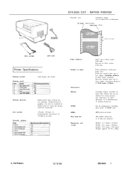
DFX-5000 1 Life expectancy (in black only (#8766). MATRIX PRINTER
Printable area:
Continuous paper 4 to 16 inches (101 to 406.4mm)
left margin
0.51 to 1.22 in right margin 0.51 in \ \
ribbon cartridge
power cable
Paper thickness:
Printer Specifications
Printing method: Printing speed:
9-pin Impact dot matrix
Printing direction: Line spacing: Printable ...
Product Information Guide - Page 4
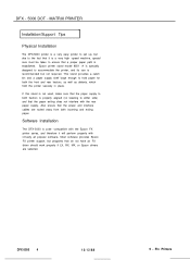
... the rear paper supply.
Most software provides Epson FX printer support, but programs that the power and interface cables are selected. Pin Printers DFX-5000 4
12/12/88
9 - Also ensure that do not have an FX driver should work properly if LX, RX, MX, or Epson drivers are routed away from both incoming and exiting paper. DFX - 5000 DOT - If this...
User Manual - Page 8
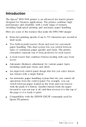
...Here are some of the features that combines bottom feeding with the EPSON ESC/P commands used by Epson FX printers. A front tractor that make the DFX-5000 unique:
Extra-fast printing speeds of a button. An automatic paper...can tear it off, and then reverses it is an advanced dot matrix printer designed for each tractor. Two built-in draft mode. For example, you control all operations from...
User Manual - Page 17
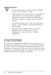
... same circuit with large motors or other appliances that might disturb the power supply. See Chapters 2 and 3 for reference as loudspeakers or the base units of power can wipe out information in both your computer's memory and your printer.
1-6 Setting Up the Printer Accidental disruption of cordless telephones. WARNING: l Avoid locations that are controlled by...
User Manual - Page 76
... N T / R E A R 11
aREnD" I '=PAOUPTER
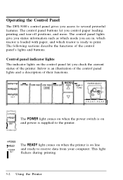
The POWER light comes on when the power switch is on and power is supplied to the printer.
,omP=OREWAEDYR The READY light comes on line
I .W.F-R. The following sections...Using the Printer The control panel lights give you status information such as which mode you access to several powerful features. Operating the Control Panel
The DFX-5000's control ...
Service Manual - Page 3

... COMPONENTS.
5. REPLACE MALFUNCTIONING COMPONENTS ONLY WITH THOSE COMPONENTS BY THE MANUFACTURE; MAKE CERTAIN THAT THE SOURCE VOLTAGE IS THE SAME AS THE RATED VOLTAGE, LISTED ON THE SERIAL NUMBER/RATING PLATE.
WHEN THE POWER SUPPLY CABLE MUST BE CONNECTED, USE EXTREME CAUTION IN WORKING ON POWER SUPPLY AND OTHER ELECTRONIC COMPONENTS.
1. IF THE EPSON PRODUCT HAS...
Service Manual - Page 34

...1.6 MAIN COMPONENTS
The main components of the DFX-5000+ are :
Printer mechanism (M-3C11)
Main control board (C117 MAIN board assembly)
Power supply board ( C117 PSB/PSE board assembly)
Control panel (C117 PNL board assembly)
Housing
Connector Junction Board
@
Y
c
Figure 1-26. Main Components
1-26
Rev. These
e
main components are designed fix easy removal and replacement. A
Service Manual - Page 40
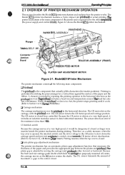
... (dot matrix patterns). Because the front and rear carriage guide shafts which hold the @rriage are purposely mounted off-center, the carriage moves as the printhead moves). The CR motor is printed by moving the carriage (and printhead) either forward or backward. A character is closed . DFx-5tW(h Sewka Manual
Oparathg Prfncipka
2.1 OVERVIEW OF PRINTER...
Service Manual - Page 51

... Overview
Figure 2-14 shows a block diagram of these two boards is in the operation of the power supply board.
Surga-cut - Omratinf7 Principles
DEW5000+ Service Manual
2.2 POWER SUPPLY OPERATION
The printer can be powered by either of the boards. Smoothing
Circuil
circuit
circuit
~
Main swhching
Smoothing
Circuit (1)
Circuit
a
a
t
rllMain swtching Circuit (2)
Smoothing...
Service Manual - Page 52

... circuits perform voltage control and over-current limiting for approximately thee minutes after the printer is turned off . To prevent a surge in the current, the power supply board cannot recover for each voltage. Table 2-2. e m %i;'
DFX-5000+ Sendee Mama! O~atfng Princi@aa
The power supply board converts the AC voltage to the DC voltages required to prevent printhead...
Service Manual - Page 53
... printhead driver is damaged. When the C117 power supply board assembly receives this signal, it stops creating +35 VDC and +5 VDC. A Operating Principles
DFX-5000+ Service Manual
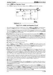
2.2.2 +5 VDC Line Regulator... +5 VDC line exceeds +7 VDC, the current flows to the power supply board. If this control circuit.
When the printer is turned on , and the voltage of the primary side. ...
Service Manual - Page 54
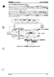
...signal, the +35 VDC line rises from +13 V to +35 V. DFX-5000+ Service Manual
operating Principbe
2.2.3 +35 VDC Line Regulator Circuit
When the printer is turned on , the primary side of T1 and T2 prevent current flow... p":. ,":.>.. This system uses few parts and a small transformer, and is ok used when a small power supply is turned off, the currmt flows to the gate of the transformer coil.
Service Manual - Page 56

...control circuit for the power supply board, control of the LEDs on or off . The CPU controls all the printer operations via the ...power supply
board assembly to the ports. This CPU is the TMP96C14 CPU (IC1). The CPU executes programs stored in the internal mask ROM and IM external PROM (IC4). The CPU starts executing a program upon r-iving the reset signal from an external device. DEX-5000...
Service Manual - Page 63

...
10. +35 VDC voltage drop sensor (signal interface) When the +35 VDC line voltages drop, the C117 power supply board assembly sends a HIGH CLIMIT signal to 0.7 mm
9.
Paper present: The voltage level is detected and the printer beeps. (Refer to Section 1.4.15, lluzza Operation.)
2-24
Rev. Platen gap home position sensor
D Detection form...
Service Manual - Page 72

... power supply board assembly receives this signal, it stops the output voltage and the printer ...power of IC7 go LOW, the FET gates are biased, and the FETs are turned on so that current
flows through the printhead coil. When the temperature rises abnormally, printing stops at once until the temperature cools. The CPU monitors the head temperature and head fan temperature. A
2-33 . DEX-5000...
Service Manual - Page 74

...Power Supply Board
Assembly 3-18
3.2.4.3 Removing the Cl 17 MAIN Board Assembly 3-18 3.2.4.4 Removing the AC Inlet 3-19
3.2.4.5 Removing the C117 PNL Board Assembly 3-20
3.2.5 Removing the Interlock Switch Assembly 3-21 3.2.6 Removing the Printer Mechanism 3-22
3.2.7 Printer... DISASSEMBLY AND ASSEMBLY
3-7
3.2.1 Replacing the Printhead 3-7
3.2.2 Replacing the ROM 3-9
3.2.3 Removing the...
Service Manual - Page 75

... Sensor 3-35 Figure 3-47. Packing the DFX-5000 3-2 Figure3-3. Dial Gauge Base 3-4 Figure3-5....Printer Mechanism 3-23 Figure 3-30. Removing the PWSensor 3-35 Figure 3-48. Thickness Gauge 3-5 Figure3-7. Removing the Left and Right Side Covers 3-11 Figure3-12. Removing the Cl 17 Power Supply...-15. Removing the Printer Mechanism 3-22 Figure 3-29. Replacing the ROM 3-9 Figure3-10...
Service Manual - Page 88

... Assembly
DEX-5000+ Service Manual
3. After you remove the right side cover, you can replace the input fuse for the C117 power supply board assembly. Then remove the screws on the right side and remove the front cover with the 2 hinges.
Removing the Fuse
4. Make sure the new fuse meets the printer's AC power specifications. ,CARRIAGE...
Service Manual - Page 150
...the DRERR signal at CN3.
Wait until the printer prints again. DFX-5000+ Service Manual
Troubleshooting
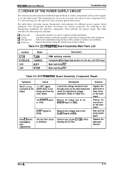
5.3 REPAIR OF THE POWER SUPPLY CIRCUIT
This section provides detailed troubleshooting methods to...F1 blows immediately after replacement. The DRERR signal is defective.
The table below provides causes, checkpoints, and solutions for different power supply circuit problems. The checkpoints...
Service Manual - Page 154
...mv
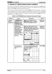
. CI17 MAIN Board Assembly Component Repair
Symptom
The printer does not operate at the voltage waveform for the ...ignore this section.
I
3LY>=J ,66s
i
A r-000s
1
I
Solution Replace the head driver.
This information is turned on and verify the voltage waveform for...power supply). Check these values and rep, air the board as described in the C117 MAIN board. Table 5-6.
DFX-5000+...
Similar Questions

Power Supply Issue
We have delivery trucks with these printers installed. They work great other than one of the printer...
We have delivery trucks with these printers installed. They work great other than one of the printer...
(Posted by Loren78212 3 years ago)

Where Can I Find Printer Driver For Epson Dfx 5000 For Windows 7
(Posted by 666sijconle 9 years ago)

Technical Fault
Hi ! i have printer Epson LQ-2190, when printer power is on, head is stucking and front panel lights...
Hi ! i have printer Epson LQ-2190, when printer power is on, head is stucking and front panel lights...
(Posted by irfanirshaad 11 years ago)

Interchangeable Epson Printead
Can the Epson DFX5000+ Printhead be used on an Epson DFX5000? If so how is the ribbon connection con...
Can the Epson DFX5000+ Printhead be used on an Epson DFX5000? If so how is the ribbon connection con...
(Posted by cg96557 11 years ago)
