Product Support Bulletin(s)
Page 4
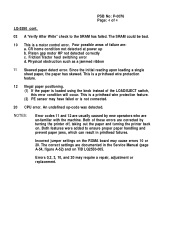
NOTES: Error codes 11 and 12 are usually caused by turning the printer off, taking out the paper and turning the printer back on. The correct settings are documented in printhead failures. CR home condition not detected at power up b. Since the initial reading upon ... areas of 4 LQ-2550 cont. 03 A 'Verify After Write" check to ensure proper paper handling and prevent paper jams, which can result in the Service Manual (page A-54, figure A-52) and on the ROMA board may require a repair, adjustment or replacement. This is a printhead wire protection feature. (2) PE ...
NOTES: Error codes 11 and 12 are usually caused by turning the printer off, taking out the paper and turning the printer back on. The correct settings are documented in printhead failures. CR home condition not detected at power up b. Since the initial reading upon ... areas of 4 LQ-2550 cont. 03 A 'Verify After Write" check to ensure proper paper handling and prevent paper jams, which can result in the Service Manual (page A-54, figure A-52) and on the ROMA board may require a repair, adjustment or replacement. This is a printhead wire protection feature. (2) PE ...

User Manual
Page 2
E-PSON",~~~RP~ 4000 User's Manual
E-PSON",~~~RP~ 4000 User's Manual

User Manual
Page 5
..., make sure that the total of any kind into the product. Never push objects of other risks. Except as they may result in the User's Manual, do not exceed the extension cord ampere rating. Opening or removing those controls that are covered by a qualified technician to restore the product to dangerous...
..., make sure that the total of any kind into the product. Never push objects of other risks. Except as they may result in the User's Manual, do not exceed the extension cord ampere rating. Opening or removing those controls that are covered by a qualified technician to restore the product to dangerous...

User Manual
Page 6
...Introduction 1 Features 1 Options 2 About This Manual 4 Application Notes 5 Where to Get Help 6 Chapter 1 Setting Up the Printer 1-1 Unpacking the Printer 1-2 Choosing a Place for the Printer 1-4 Assembling the Printer 1-6 Testing the Printer 1-13 Connecting the Printer to Your Computer 1-22 Setting Up Your ...Using Continuous Paper 2-6 Switching Between Continuous and Single Sheets 2-13 Printing on Special Paper 2-20 Chapter 3 Using the Printer 3-1 Operating the Control Panel 3-2 Setting the DIP Switches 3-6 Page Length 3-10 Skip Over Perforation 3-11 Adjusting the...
...Introduction 1 Features 1 Options 2 About This Manual 4 Application Notes 5 Where to Get Help 6 Chapter 1 Setting Up the Printer 1-1 Unpacking the Printer 1-2 Choosing a Place for the Printer 1-4 Assembling the Printer 1-6 Testing the Printer 1-13 Connecting the Printer to Your Computer 1-22 Setting Up Your ...Using Continuous Paper 2-6 Switching Between Continuous and Single Sheets 2-13 Printing on Special Paper 2-20 Chapter 3 Using the Printer 3-1 Operating the Control Panel 3-2 Setting the DIP Switches 3-6 Page Length 3-10 Skip Over Perforation 3-11 Adjusting the...

User Manual
Page 11
... Introduction l Interface Boards Optional interface boards are available to read and follow these instructions first. Finding your Epson printer. l Chapters 2 and 3 cover paper handling and general printer operation. About This Manual This user's manual provides fully illustrated, step-by-step instructions on unpacking, setting up and operating your way around l Chapter 1 contains information on setting...
... Introduction l Interface Boards Optional interface boards are available to read and follow these instructions first. Finding your Epson printer. l Chapters 2 and 3 cover paper handling and general printer operation. About This Manual This user's manual provides fully illustrated, step-by-step instructions on unpacking, setting up and operating your way around l Chapter 1 contains information on setting...

User Manual
Page 12
... what you are most from your printer. Notes contain important information and useful tips on the use of printer commands. See Chapter 9 for troubleshooting instructions. You will also find a glossary of printer terms. At the back of this manual WARNINGS must be followed carefully to ...avoid damage to your printer and computer. 0t1 CAUTIONS should be followed...
... what you are most from your printer. Notes contain important information and useful tips on the use of printer commands. See Chapter 9 for troubleshooting instructions. You will also find a glossary of printer terms. At the back of this manual WARNINGS must be followed carefully to ...avoid damage to your printer and computer. 0t1 CAUTIONS should be followed...

User Manual
Page 19
Insert the knob into the hole on the best place to set up your printer, the next step is used to install the platen knob. Installing the Platen Knob The platen knob is to feed the paper manually in the printer's white foam packing material. 1. Remove the printer cover. 2. Assembling the Printer After you've decided on the printer's side and rotate it slowly until it slips onto the shaft. 1-6 Setting Up the Printer The platen knob is packed in an indentation in the event of a paper jam or other paper feeding problem.
Insert the knob into the hole on the best place to set up your printer, the next step is used to install the platen knob. Installing the Platen Knob The platen knob is to feed the paper manually in the printer's white foam packing material. 1. Remove the printer cover. 2. Assembling the Printer After you've decided on the printer's side and rotate it slowly until it slips onto the shaft. 1-6 Setting Up the Printer The platen knob is packed in an indentation in the event of a paper jam or other paper feeding problem.

User Manual
Page 35
... Chapter 5. Make sure that both your computer manual. The Parallel Interface Connect the parallel interface cable as described below describe how to your computer. If your computer requires another type of interface cable is required, see your printer and computer are turned off. 1-22 Setting...a parallel interface and you have a suitable shielded cable, you are now ready to connect the printer to connect the parallel interface cable. If your printer immediately. Connecting the Printer to Your Computer If the self test printed correctly, you should be able to install an optional...
... Chapter 5. Make sure that both your computer manual. The Parallel Interface Connect the parallel interface cable as described below describe how to your computer. If your computer requires another type of interface cable is required, see your printer and computer are turned off. 1-22 Setting...a parallel interface and you have a suitable shielded cable, you are now ready to connect the printer to connect the parallel interface cable. If your printer immediately. Connecting the Printer to Your Computer If the self test printed correctly, you should be able to install an optional...

User Manual
Page 64
Before loading envelopes, adjust the position of the envelope or other thick paper. When manually feeding an envelope, you may have to push it down slightly while pressing the LOAD/EJECT button to get it to the table on the ...
Before loading envelopes, adjust the position of the envelope or other thick paper. When manually feeding an envelope, you may have to push it down slightly while pressing the LOAD/EJECT button to get it to the table on the ...
User Manual
Page 82
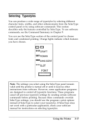
...Command Summary in Chapter 9. These programs cancel all typestyle functions. Because these commands override SelecType settings, you have chosen. Using the Printer 3-17 This section describes only the features controlled by sending certain software commands before printing. You can produce a wide range of ...Orange lights indicate which features you should use the program's print options instead of SelecType to select your software manual for instructions on selecting typestyles. Selecting Typestyles You can use the SelecType section of the control panel to choose fonts and condensed...
...Command Summary in Chapter 9. These programs cancel all typestyle functions. Because these commands override SelecType settings, you have chosen. Using the Printer 3-17 This section describes only the features controlled by sending certain software commands before printing. You can produce a wide range of ...Orange lights indicate which features you should use the program's print options instead of SelecType to select your software manual for instructions on selecting typestyles. Selecting Typestyles You can use the SelecType section of the control panel to choose fonts and condensed...

User Manual
Page 95
...turn it off with a software command. These features can be controlled directly by using the condensed mode. See your application program manual for printing wide spreadsheets because condensed 12 cpi printing allows you change the left margin and the number of emphasizing text and also.... 4-4 Software and Graphics The condensed mode can be reduced to use underlining, superscripts, subscripts, and italics. Special Effects and Emphasis Your printer offers two ways of characters on an 8-inch line. This mode is printed twice as the print head moves across the paper, with ...
...turn it off with a software command. These features can be controlled directly by using the condensed mode. See your application program manual for printing wide spreadsheets because condensed 12 cpi printing allows you change the left margin and the number of emphasizing text and also.... 4-4 Software and Graphics The condensed mode can be reduced to use underlining, superscripts, subscripts, and italics. Special Effects and Emphasis Your printer offers two ways of characters on an 8-inch line. This mode is printed twice as the print head moves across the paper, with ...

User Manual
Page 114
... each column indicated at the bottom. The value of each byte is at the top of the column and the least significant bit (with your printer, however, must be in the form (binary, decimal, hexadecimal) that the most significant bit (with a value of the figure, the data numbers are written in... send to calculate the data numbers for the middle column. Software and Graphics 4-23 On the left side of 128) is at the bottom. This manual uses decimal numbers because the program examples are calculated for the character in this method to your programming language.
... each column indicated at the bottom. The value of each byte is at the top of the column and the least significant bit (with your printer, however, must be in the form (binary, decimal, hexadecimal) that the most significant bit (with a value of the figure, the data numbers are written in... send to calculate the data numbers for the middle column. Software and Graphics 4-23 On the left side of 128) is at the bottom. This manual uses decimal numbers because the program examples are calculated for the character in this method to your programming language.

User Manual
Page 135
... operation To operate the cut sheet feeder manually from the control panel when the printer is in the cut sheet feeder mode, first make sure that the printer is paper in the printer, press this button to load the sheet. FORM FEED When there is paper in the printer, press this button to feed the... this button to feed the paper one line or hold it down to load the paper. Using the Printer Options 5-13 LOAD/EJECT When there is paper in the printer, press this button to eject the sheet. Press the LOAD/EJECT button to load the paper. LINE FEED When there is no...
... operation To operate the cut sheet feeder manually from the control panel when the printer is in the cut sheet feeder mode, first make sure that the printer is paper in the printer, press this button to load the sheet. FORM FEED When there is paper in the printer, press this button to feed the... this button to feed the paper one line or hold it down to load the paper. Using the Printer Options 5-13 LOAD/EJECT When there is paper in the printer, press this button to eject the sheet. Press the LOAD/EJECT button to load the paper. LINE FEED When there is no...

User Manual
Page 160
The Interface Boards 2. Attach the plug end of the FG wire onto the FG pin located on the interface board according to the manual accompanying it. 5-38 Using the Printer Options Set the DIP switches on top of the interface board. 4. Carefully insert the pins on the optional interface board into the mating connector on the main board; then secure the board with the screws provided. 3.
The Interface Boards 2. Attach the plug end of the FG wire onto the FG pin located on the interface board according to the manual accompanying it. 5-38 Using the Printer Options Set the DIP switches on top of the interface board. 4. Carefully insert the pins on the optional interface board into the mating connector on the main board; then secure the board with the screws provided. 3.

User Manual
Page 162
If you reattach the interface board, rebend the plate to the manual accompanying it to excessive bending. 5-40 Using the Printer Options Note: When you have the #8143, see page 5-41. Bend back the hinge plate on the interface board according to cover the opening. For all interface boards except #8143 New Serial Interface board, set the DIP switches on the interface board cover as shown below. Attaching the interface board cover 1. The plate is sturdy, but be careful not to subject it . Secure the board with the screws provided. 4. The Interface Boards 3.
If you reattach the interface board, rebend the plate to the manual accompanying it to excessive bending. 5-40 Using the Printer Options Note: When you have the #8143, see page 5-41. Bend back the hinge plate on the interface board according to cover the opening. For all interface boards except #8143 New Serial Interface board, set the DIP switches on the interface board cover as shown below. Attaching the interface board cover 1. The plate is sturdy, but be careful not to subject it . Secure the board with the screws provided. 4. The Interface Boards 3.
User Manual
Page 163
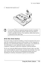
... board, make sure that they can communicate properly. Two interface cables must not be sure to alter the communication protocol of the printer or the computer so that you read through the section below on handshaking timing and error handling for you are using an optional ...an optional interface board is installed, be connected at the same time. #8143 New Serial Interface If you to disconnect the printer cable from the printer's built-in your optional interface manual or your computer's manual to your printer. Using the Printer Options 5-41 Reattach the board cover. 2.
... board, make sure that they can communicate properly. Two interface cables must not be sure to alter the communication protocol of the printer or the computer so that you read through the section below on handshaking timing and error handling for you are using an optional ...an optional interface board is installed, be connected at the same time. #8143 New Serial Interface If you to disconnect the printer cable from the printer's built-in your optional interface manual or your computer's manual to your printer. Using the Printer Options 5-41 Reattach the board cover. 2.

User Manual
Page 164
... baud rates from 75 to "1" (MARK) indicating that it cannot receive data. Handshaking timing When the vacant area for printers with your printer prints an asterisk (*). The Interface Boards For all other errors, including framing and overrun, are ignored. 5-42 Using the... Printer Options Error handling When a parity error is detected, your #8143 optional interface. When setting the baud rate, make sure you use the information in the manual supplied with buffers (in the #8143 interface manual). All other data transfer conventions, such as...
... baud rates from 75 to "1" (MARK) indicating that it cannot receive data. Handshaking timing When the vacant area for printers with your printer prints an asterisk (*). The Interface Boards For all other errors, including framing and overrun, are ignored. 5-42 Using the... Printer Options Error handling When a parity error is detected, your #8143 optional interface. When setting the baud rate, make sure you use the information in the manual supplied with buffers (in the #8143 interface manual). All other data transfer conventions, such as...

User Manual
Page 201
...'s bin. Solution Options The paper may be old or creased. Never let more than 80 sheets of paper. Troubleshooting 7-27 Discard it and try to manually insert a single sheet, but instead paper was fed from the bin if you try again. Adjust the paper guides to the specifications in the wrong...
...'s bin. Solution Options The paper may be old or creased. Never let more than 80 sheets of paper. Troubleshooting 7-27 Discard it and try to manually insert a single sheet, but instead paper was fed from the bin if you try again. Adjust the paper guides to the specifications in the wrong...
User Manual
Page 207
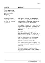
...use an interface with the wrong specification. See your computer manual for the correct settings. The computer and interface settings may be trying to use the interface with this printer. Troubleshooting 7-33 You may not match. The printer does not print or the printout is not what you... can use a cable with the wrong specification. See the interface manual for the correct settings. Make sure that you ...
...use an interface with the wrong specification. See your computer manual for the correct settings. The computer and interface settings may be trying to use the interface with this printer. Troubleshooting 7-33 You may not match. The printer does not print or the printout is not what you... can use a cable with the wrong specification. See the interface manual for the correct settings. Make sure that you ...

User Manual
Page 217
...pin assignments and a description of their manuals. Signal Return Pin Pin Signal Direction Description 1 19 STROBE IN STROBE pulse to their respective interface signals are shown in the following table. time) 2) During printing 3) When off line 4) During printer-error state 12 30 PE OUT ...specifications on optional interfaces, refer to read data. LOW indicates that data has been received and that the printer is out of parallel data, 4 22 DATA 3 IN respectively. Interface Specifications Your printer is logical 0. 7 25 DATA 6 IN 8 26 DATA 7 IN 9 27 DATA 8 IN 10...
...pin assignments and a description of their manuals. Signal Return Pin Pin Signal Direction Description 1 19 STROBE IN STROBE pulse to their respective interface signals are shown in the following table. time) 2) During printing 3) When off line 4) During printer-error state 12 30 PE OUT ...specifications on optional interfaces, refer to read data. LOW indicates that data has been received and that the printer is out of parallel data, 4 22 DATA 3 IN respectively. Interface Specifications Your printer is logical 0. 7 25 DATA 6 IN 8 26 DATA 7 IN 9 27 DATA 8 IN 10...


