
Service Manual
Page 168
...damages to clear the error. There detected any Ink Cartridge slot without cartridge. Recovery PRINTER COVER OPEN LCD TOP COVER OPEN Explanation Generated when Printer Cover is full. If error is not cleared after cover is closed, check ...Replace the P Cover Open Sensor.(p.219) Troubleshooting Troubleshooting Based on Panel Messages 168 Recovery Open I/H Cover and properly install the Ink Cartridge indicated by the LCD panel. Pull down the Ink Lever to printing head if this error. † When cover was OFF, power will turn OFF after capping printhead. EPSON Stylus Pro 4000...
...damages to clear the error. There detected any Ink Cartridge slot without cartridge. Recovery PRINTER COVER OPEN LCD TOP COVER OPEN Explanation Generated when Printer Cover is full. If error is not cleared after cover is closed, check ...Replace the P Cover Open Sensor.(p.219) Troubleshooting Troubleshooting Based on Panel Messages 168 Recovery Open I/H Cover and properly install the Ink Cartridge indicated by the LCD panel. Pull down the Ink Lever to printing head if this error. † When cover was OFF, power will turn OFF after capping printhead. EPSON Stylus Pro 4000...
Service Manual
Page 181
... properly and free from short circuit or broken wire. † Remedy 1. In such a case, this message is displayed and the printer stops operating. † Cause of trouble „ Print Heat increase due to empty jetting of ink „ Faulty contact of Head...If the same error occurs immediately, replace the Printhead (p278) SERVICE REQ. 0001001D † Error meaning: CR servo parameter error † Explanation There may be applied to the CR Motor. Replace the CR Encoder Sensor (p273) 4. Replace the Motor Assy., CR (p264) 5. EPSON Stylus Pro 4000 Revision B SERVICE REQ. 0001001B &#...
... properly and free from short circuit or broken wire. † Remedy 1. In such a case, this message is displayed and the printer stops operating. † Cause of trouble „ Print Heat increase due to empty jetting of ink „ Faulty contact of Head...If the same error occurs immediately, replace the Printhead (p278) SERVICE REQ. 0001001D † Error meaning: CR servo parameter error † Explanation There may be applied to the CR Motor. Replace the CR Encoder Sensor (p273) 4. Replace the Motor Assy., CR (p264) 5. EPSON Stylus Pro 4000 Revision B SERVICE REQ. 0001001B &#...

Service Manual
Page 184
...undefined NMI was detected at CPU. † Remedy Replace the Printhead (p278) SERVICE REQ. 00010029 † Error meaning... Turn on the printer in Maintenance Mode 2, execute "RTC&USBID&IEEE1394ID" and enter date of "RTC." Replace the C511 MAIN ...Board (p221) SERVICE REQ. 0001002B † Error meaning: PF ASIC ECU error † Cause of trouble „ Faulty firmware (irregular overwriting of register, etc.) „ Damaged drive circuit board (break in pattern, etc.) † Remedy 1. Remove the battery once with the power turned off once and on . 2. EPSON Stylus Pro 4000...
...undefined NMI was detected at CPU. † Remedy Replace the Printhead (p278) SERVICE REQ. 00010029 † Error meaning... Turn on the printer in Maintenance Mode 2, execute "RTC&USBID&IEEE1394ID" and enter date of "RTC." Replace the C511 MAIN ...Board (p221) SERVICE REQ. 0001002B † Error meaning: PF ASIC ECU error † Cause of trouble „ Faulty firmware (irregular overwriting of register, etc.) „ Damaged drive circuit board (break in pattern, etc.) † Remedy 1. Remove the battery once with the power turned off once and on . 2. EPSON Stylus Pro 4000...

Service Manual
Page 186
...Eject Unit) due to paper jam or foreign object. † Remedy Recover by turning power OFF and back ON. Replace the Paper Eject Phase Sensor (p348) SERVICE REQ. 00010034 † Error meaning: Paper eject movement error † Cause...Replace the Printhead (p278) SERVICE REQ. 00010038 † Error meaning: Transistor thermistor error † Cause of trouble Home position for paper eject switching cannot be done by turning power OFF and back ON after removing paper or foreign object. Check if the "Harness, Head" is connected correctly, and correct it if abnormal. 2. EPSON Stylus Pro 4000...
...Eject Unit) due to paper jam or foreign object. † Remedy Recover by turning power OFF and back ON. Replace the Paper Eject Phase Sensor (p348) SERVICE REQ. 00010034 † Error meaning: Paper eject movement error † Cause...Replace the Printhead (p278) SERVICE REQ. 00010038 † Error meaning: Transistor thermistor error † Cause of trouble Home position for paper eject switching cannot be done by turning power OFF and back ON after removing paper or foreign object. Check if the "Harness, Head" is connected correctly, and correct it if abnormal. 2. EPSON Stylus Pro 4000...
Service Manual
Page 192
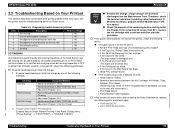
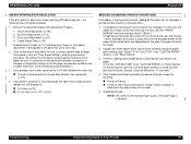
...If the power cleaning does not recover the printer, check the following particulars. † Execute head cleaning or initial ink charge. ...EPSON Stylus Pro 4000 Revision B 3.3 Troubleshooting Based on Your Printout 192 could occur.) • Print Head failure • Execute power cleaning again. † If the trouble still occur even after checking the items listed above, replace...; Printhead (p278) • C511 MAIN Board (p221) Troubleshooting Troubleshooting Based on Your Printout This section describes conceivable print quality problems that may occur with a specific ink color. ...
...If the power cleaning does not recover the printer, check the following particulars. † Execute head cleaning or initial ink charge. ...EPSON Stylus Pro 4000 Revision B 3.3 Troubleshooting Based on Your Printout 192 could occur.) • Print Head failure • Execute power cleaning again. † If the trouble still occur even after checking the items listed above, replace...; Printhead (p278) • C511 MAIN Board (p221) Troubleshooting Troubleshooting Based on Your Printout This section describes conceivable print quality problems that may occur with a specific ink color. ...
Service Manual
Page 193
...set the drying time (the time until auto paper cutting is carried out after replacing the C511 Main Board with weak edges which cannot move smoothly along the paper... end on the paper's printed surface, check the following parts. „ Printhead (p278) „ Printer Mechanism (SP) (p236) SMUDGED OR MARRED PRINTOUT (FRONT SIDE) If smudging... Adjustment Program. 1. Nozzle Bi-D Adjustment (p.381) 2. If the printer's condition is not improved by the head, etc. Maximum: 10 seconds) 4. EPSON Stylus Pro 4000 Revision B UNEVEN PRINTING/POOR RESOLUTION If the print quality is abnormal...
...set the drying time (the time until auto paper cutting is carried out after replacing the C511 Main Board with weak edges which cannot move smoothly along the paper... end on the paper's printed surface, check the following parts. „ Printhead (p278) „ Printer Mechanism (SP) (p236) SMUDGED OR MARRED PRINTOUT (FRONT SIDE) If smudging... Adjustment Program. 1. Nozzle Bi-D Adjustment (p.381) 2. If the printer's condition is not improved by the head, etc. Maximum: 10 seconds) 4. EPSON Stylus Pro 4000 Revision B UNEVEN PRINTING/POOR RESOLUTION If the print quality is abnormal...
Service Manual
Page 278
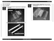
HEAD EXCHANGE SUPPORT TOOL HEAD EXCHANGE SUPPORT TOOL (Adjust Plate) CR SUS PLATE SUPPORT TOOL Disassembly & Assembly Disassembly Procedures 278 CUTTER CAP Revision B CHECK P O IN T „ Be sure to install the "Adjust Plate" to the rear of the "HEAD EXCHANGE SUPPORT TOOL" before removing the "Printhead". EPSON Stylus Pro 4000 4.2.8 Ink System 4.2.8.1 Printhead CHECK P O IN T „ Figures below shows the required tools in replacing the "Printhead".
HEAD EXCHANGE SUPPORT TOOL HEAD EXCHANGE SUPPORT TOOL (Adjust Plate) CR SUS PLATE SUPPORT TOOL Disassembly & Assembly Disassembly Procedures 278 CUTTER CAP Revision B CHECK P O IN T „ Be sure to install the "Adjust Plate" to the rear of the "HEAD EXCHANGE SUPPORT TOOL" before removing the "Printhead". EPSON Stylus Pro 4000 4.2.8 Ink System 4.2.8.1 Printhead CHECK P O IN T „ Figures below shows the required tools in replacing the "Printhead".

Service Manual
Page 283
...a new one, be sure to write down the Head Rank ID of the new one (21 characters in the figure bilow. Printhead Removal Print Head Harness, Head Circle Mark Figure 4-112. Absorber, CR Caution: Head, Harness Revision B Carriage, C C.P.P. 2...." to Chapter 5 "Adjustment" (p.354) and perform specified adjustments after replacing or removing the "Printhead". EPSON Stylus Pro 4000 12. Remove the three screws that secure the "Printhead", and then remove the "Printhead" from the "Printhead", and then remove the "Printhead". (Refer to Figure 4-110.) Figure 4-111. Harness, Head Removal...
...a new one, be sure to write down the Head Rank ID of the new one (21 characters in the figure bilow. Printhead Removal Print Head Harness, Head Circle Mark Figure 4-112. Absorber, CR Caution: Head, Harness Revision B Carriage, C C.P.P. 2...." to Chapter 5 "Adjustment" (p.354) and perform specified adjustments after replacing or removing the "Printhead". EPSON Stylus Pro 4000 12. Remove the three screws that secure the "Printhead", and then remove the "Printhead" from the "Printhead", and then remove the "Printhead". (Refer to Figure 4-110.) Figure 4-111. Harness, Head Removal...

Service Manual
Page 286
... D JU S TM E N T R E Q U IR E D Be sure to refer to remove the joint section. 6-2. EPSON Stylus Pro 4000 3. Draw out the "Plate, Damper" with a plier or a similar tool. (Refer to Figure 4-114.) C A U T ...Tube, Supply, Ink", to Chapter 5 "Adjustment" (p.354) and perform specified adjustments after replacing or removing the "Valve Assy., Head". Release the tab and remove the "Valve Assy...Separate the "Carriage, C" from the "Carriage Unit". (Refer to "4.2.8.1 Printhead" (p278).) 5. "Plate, Damper" Drawing Joint Section Tab 1 2 1 Valve Assy., Head Film Area (both sides) Disassembly ...
... D JU S TM E N T R E Q U IR E D Be sure to refer to remove the joint section. 6-2. EPSON Stylus Pro 4000 3. Draw out the "Plate, Damper" with a plier or a similar tool. (Refer to Figure 4-114.) C A U T ...Tube, Supply, Ink", to Chapter 5 "Adjustment" (p.354) and perform specified adjustments after replacing or removing the "Valve Assy., Head". Release the tab and remove the "Valve Assy...Separate the "Carriage, C" from the "Carriage Unit". (Refer to "4.2.8.1 Printhead" (p278).) 5. "Plate, Damper" Drawing Joint Section Tab 1 2 1 Valve Assy., Head Film Area (both sides) Disassembly ...
Service Manual
Page 355
... by Part/Unit" and perform required operations in proper order without omitting steps. EPSON Stylus Pro 4000 Revision B 5.1 Overview This section describes the adjustment procedures necessary after being replaced or removed are performed improperly. 5.1.2 Advance of each adjustment item. Product operations ...(Disassembly/Reassembly Reference Page) Main Circuit Board*1 (C511 MAIN Board (p221)) Cleaning Unit*2 (p.309) Printhead (p278) Damper (Valve Assy., Head (p.284)) AS Mechanical Unit (Printer Mechanism (SP) (p.236)) ASF Unit (p.240) Motor Motor Assy., CR (p264) Motor Assy., ...
... by Part/Unit" and perform required operations in proper order without omitting steps. EPSON Stylus Pro 4000 Revision B 5.1 Overview This section describes the adjustment procedures necessary after being replaced or removed are performed improperly. 5.1.2 Advance of each adjustment item. Product operations ...(Disassembly/Reassembly Reference Page) Main Circuit Board*1 (C511 MAIN Board (p221)) Cleaning Unit*2 (p.309) Printhead (p278) Damper (Valve Assy., Head (p.284)) AS Mechanical Unit (Printer Mechanism (SP) (p.236)) ASF Unit (p.240) Motor Motor Assy., CR (p264) Motor Assy., ...

Service Manual
Page 356
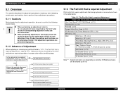
...Printhead Slant Adjustment (PF) { --- P.384 14 Multi Sensor Level Adjustment { --- P.391 18 Multi Sensor Adjustment for each part/unit that has been replaced or removed is shown in the table below. P.388 19 Auto Uni-d Adjustment { --- EPSON Stylus Pro 4000...Cleaning Unit Change { --- P.370 10 Nozzle Bi-D Adjustment { { P.381 11 Printhead Slant Adjustment (PF) { --- Note "*1": RP = Replacement with new part "*2": RM = Removal only "*3": Refer to "P.400 and P.409" for 8-color machine and 4-color machine, respectively. P.417 6 Check Alignment { --- P.393 8 Nozzle Bi-D ...
...Printhead Slant Adjustment (PF) { --- P.384 14 Multi Sensor Level Adjustment { --- P.391 18 Multi Sensor Adjustment for each part/unit that has been replaced or removed is shown in the table below. P.388 19 Auto Uni-d Adjustment { --- EPSON Stylus Pro 4000...Cleaning Unit Change { --- P.370 10 Nozzle Bi-D Adjustment { { P.381 11 Printhead Slant Adjustment (PF) { --- Note "*1": RP = Replacement with new part "*2": RM = Removal only "*3": Refer to "P.400 and P.409" for 8-color machine and 4-color machine, respectively. P.417 6 Check Alignment { --- P.393 8 Nozzle Bi-D ...


