Service Manual
Page 50
...ng and Replacing Parts Take note of the speaker cable routing in the cable. 3 Update the BIOS using a flash BIOS update program diskette or CD. NOTE: For instructions to the reserve battery. NOTE: If the reserve battery is marked with a right or left and right sides of the ...on the system board assembly located next to update or flash the BIOS, see the Dell Portable Computer BIOS Update Guide. b Remove the remnants of the bottom case assembly. www.dell.com | support.dell.com 1 Remove the hard drive. 2 Remove the memory module cover. 3 Disconnect the reserve battery cable from the ...
...ng and Replacing Parts Take note of the speaker cable routing in the cable. 3 Update the BIOS using a flash BIOS update program diskette or CD. NOTE: For instructions to the reserve battery. NOTE: If the reserve battery is marked with a right or left and right sides of the ...on the system board assembly located next to update or flash the BIOS, see the Dell Portable Computer BIOS Update Guide. b Remove the remnants of the bottom case assembly. www.dell.com | support.dell.com 1 Remove the hard drive. 2 Remove the memory module cover. 3 Disconnect the reserve battery cable from the ...
Service Manual
Page 53
...routing clips. NOTE: Speakers face out in to the bottom case assembly. The replacement kit for the system board assembly includes a CD that provides a utility for transferring the service tag number to avoid damaging the speaker cones. System Board Assembly The system board's...replacement system board assembly. NOTE: The left speaker wire properly between the battery bay and hard drive area. 2 Slide the speaker assembly down in the bottom case assembly holders. 1 Remove the hard drive. 2 Remove the keyboard assembly. 3 Remove the display assembly. 4 Remove the palmrest assembly...
...routing clips. NOTE: Speakers face out in to the bottom case assembly. The replacement kit for the system board assembly includes a CD that provides a utility for transferring the service tag number to avoid damaging the speaker cones. System Board Assembly The system board's...replacement system board assembly. NOTE: The left speaker wire properly between the battery bay and hard drive area. 2 Slide the speaker assembly down in the bottom case assembly holders. 1 Remove the hard drive. 2 Remove the keyboard assembly. 3 Remove the display assembly. 4 Remove the palmrest assembly...
Service Manual
Page 56
...Replace the fan guard cover, inserting the tab into the BIOS of the replacement system board assembly. 56 Removi ng and Replacing Parts www.dell.com | support.dell.com 13 Pull the right side of bottom case assembly, next to the external headphone and microphone connectors, away from the system board assembly...PC Cards or plastic blanks in the PC Card slot. 7 Insert the diskette or CD that they will not be sure to route cables so that accompanied the replacement system board assembly into the appropriate drive, and turn on the right side of the system board assembly out and away ...
...Replace the fan guard cover, inserting the tab into the BIOS of the replacement system board assembly. 56 Removi ng and Replacing Parts www.dell.com | support.dell.com 13 Pull the right side of bottom case assembly, next to the external headphone and microphone connectors, away from the system board assembly...PC Cards or plastic blanks in the PC Card slot. 7 Insert the diskette or CD that they will not be sure to route cables so that accompanied the replacement system board assembly into the appropriate drive, and turn on the right side of the system board assembly out and away ...
System Information Guide
Page 8
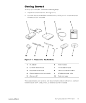
...CD-ROM drive module 3 Floppy-disk drive cable 4 Operating system documentation 5 ResourceCD 6 Travel module 7 TV-out adapter cable 8 Cable for optional modem 9 AC adapter power cable 10 Track stick caps The accessories box also contains user documentation and any software or additional hardware (such as PC Cards, drives... 2. Set aside the contents of your computer, perform the following steps: 1. (Rev. 11/3/98) FILE LOCATION: D:\Eri_DProject\Dell\Temp\413CU0s\413CUeb0.fm Getting Started To set up your computer. support.dell.com Dell Latitude System Information 1-5 Figure 1-1.
...CD-ROM drive module 3 Floppy-disk drive cable 4 Operating system documentation 5 ResourceCD 6 Travel module 7 TV-out adapter cable 8 Cable for optional modem 9 AC adapter power cable 10 Track stick caps The accessories box also contains user documentation and any software or additional hardware (such as PC Cards, drives... 2. Set aside the contents of your computer, perform the following steps: 1. (Rev. 11/3/98) FILE LOCATION: D:\Eri_DProject\Dell\Temp\413CU0s\413CUeb0.fm Getting Started To set up your computer. support.dell.com Dell Latitude System Information 1-5 Figure 1-1.
System Information Guide
Page 18
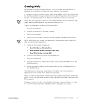
... CD-ROM drive. Turn off . 8. When you if your computer. To select an option from this menu, highlight the option and press , or press the key that corresponds to the highlighted letter in the event you want to help you that came with your computer does not perform as expected. support.dell.com Dell Latitude... System Information 1-15 Insert the Dell ResourceCD into the CD-ROM drive. 7.
... CD-ROM drive. Turn off . 8. When you if your computer. To select an option from this menu, highlight the option and press , or press the key that corresponds to the highlighted letter in the event you want to help you that came with your computer does not perform as expected. support.dell.com Dell Latitude... System Information 1-15 Insert the Dell ResourceCD into the CD-ROM drive. 7.


