Service Manual
Page 5
... Work Inside the Computer 10 Recommended Tools 11 Screw Identification 12 2 Removing and Replacing Parts Components 16 Hard Drive 17 Removing the Hard Drive 17 Replacing the Hard Drive 17 Memory Module 18 Removing the Memory Module Cover 18 Removing the Memory Modules 19 Replacing the Memory Modules 20 Mini-PCI Card Assembly 20 Removing the Mini-PCI Card Assembly 22 Replacing the Mini-PCI Card Assembly 22 Keyboard Assembly 23 Removing the Keyboard Assembly 23 Replacing the Keyboard Assembly 25 Removing the Display Assembly 26 Removing...
... Work Inside the Computer 10 Recommended Tools 11 Screw Identification 12 2 Removing and Replacing Parts Components 16 Hard Drive 17 Removing the Hard Drive 17 Replacing the Hard Drive 17 Memory Module 18 Removing the Memory Module Cover 18 Removing the Memory Modules 19 Replacing the Memory Modules 20 Mini-PCI Card Assembly 20 Removing the Mini-PCI Card Assembly 22 Replacing the Mini-PCI Card Assembly 22 Keyboard Assembly 23 Removing the Keyboard Assembly 23 Replacing the Keyboard Assembly 25 Removing the Display Assembly 26 Removing...
Service Manual
Page 6
....1-Inch Display Panel 35 Removing the Display-Feed Flex Cable (12.1-Inch Display Panel) 36 Display Assembly Latch 37 Removing the Display Assembly Latch 37 Hinge Covers 39 Removing the Hinge Covers 39 Replacing the Hinge Covers 40 Palmrest Assembly 41 Removing the Palmrest Assembly 41 Microprocessor Thermal Cooling Assembly 44 Removing the Microprocessor Thermal Cooling Assembly . . . . 44 Hybrid Cooling Fan 45 Removing the Hybrid Cooling Fan 46 Microprocessor Module 47 Removing...
....1-Inch Display Panel 35 Removing the Display-Feed Flex Cable (12.1-Inch Display Panel) 36 Display Assembly Latch 37 Removing the Display Assembly Latch 37 Hinge Covers 39 Removing the Hinge Covers 39 Replacing the Hinge Covers 40 Palmrest Assembly 41 Removing the Palmrest Assembly 41 Microprocessor Thermal Cooling Assembly 44 Removing the Microprocessor Thermal Cooling Assembly . . . . 44 Hybrid Cooling Fan 45 Removing the Hybrid Cooling Fan 46 Microprocessor Module 47 Removing...
Service Manual
Page 10
... system board, you must remove the main battery and secondary battery (if present) before you cannot shut down the computer using the computer's operating system, press and hold the power button for 4 seconds. 4 Make sure the computer is turned off and not in progress and close all open application programs. 3 Turn off the computer and all other external cables from the computer. 8 Remove any installed PC Cards...
... system board, you must remove the main battery and secondary battery (if present) before you cannot shut down the computer using the computer's operating system, press and hold the power button for 4 seconds. 4 Make sure the computer is turned off and not in progress and close all open application programs. 3 Turn off the computer and all other external cables from the computer. 8 Remove any installed PC Cards...
Service Manual
Page 16
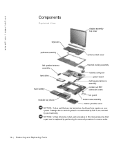
....dell.com | support.dell.com Components Exploded View display-assembly top cover keyboard palmrest assembly center control cover left speaker/antenna assembly hard drive main battery thermal cooling assembly hybrid cooling fan system board right speaker/antenna assembly modem and NIC connector covers fan guard modular bay device bottom case assembly memory module cover NOTICE: Only a certified service technician should perform repairs on your warranty. Damage due to servicing that a part can be replaced...
....dell.com | support.dell.com Components Exploded View display-assembly top cover keyboard palmrest assembly center control cover left speaker/antenna assembly hard drive main battery thermal cooling assembly hybrid cooling fan system board right speaker/antenna assembly modem and NIC connector covers fan guard modular bay device bottom case assembly memory module cover NOTICE: Only a certified service technician should perform repairs on your warranty. Damage due to servicing that a part can be replaced...

Service Manual
Page 17
... door slots in the bottom case assembly. 3 Pull the hard drive straight out of computer M3 x 5-mm screw hard drive door Removing the Hard Drive NOTICE: Disconnect the computer and any attached devices from electrical outlets, and remove any installed batteries. Removing and Repl aci ng Part s 17 Hard Drive NOTICE: The hard drive is flush with the computer case. NOTICE: To avoid ESD, ground yourself by using a wrist...
... door slots in the bottom case assembly. 3 Pull the hard drive straight out of computer M3 x 5-mm screw hard drive door Removing the Hard Drive NOTICE: Disconnect the computer and any attached devices from electrical outlets, and remove any installed batteries. Removing and Repl aci ng Part s 17 Hard Drive NOTICE: The hard drive is flush with the computer case. NOTICE: To avoid ESD, ground yourself by using a wrist...
Service Manual
Page 18
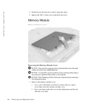
... until it snaps into place. 3 Replace the M3 x 5-mm screw in the hard drive door. b Place your finger under the cover at the indentation and lift and slide the cover open. 18 Removi ng and Replacing Parts www.dell.com | support.dell.com 2 Push down on the computer. Memory Module Memory Module Cover Removing the Memory Module Cover NOTICE: Disconnect the computer and any attached devices from electrical outlets, and remove any installed batteries.
... until it snaps into place. 3 Replace the M3 x 5-mm screw in the hard drive door. b Place your finger under the cover at the indentation and lift and slide the cover open. 18 Removi ng and Replacing Parts www.dell.com | support.dell.com 2 Push down on the computer. Memory Module Memory Module Cover Removing the Memory Module Cover NOTICE: Disconnect the computer and any attached devices from electrical outlets, and remove any installed batteries.
Service Manual
Page 20
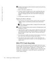
... with the slot in the socket labeled "JDIM1." www.dell.com | support.dell.com NOTICE: Read "Preparing to Work Inside the Computer" before the system board assembly can be connected to the wiring harness as appropriate; A modem, NIC, or modem and NIC combination must remove the optional mini-PCI card assembly before performing the following procedure. 1 Remove the memory module cover. 2 To release a memory module from...
... with the slot in the socket labeled "JDIM1." www.dell.com | support.dell.com NOTICE: Read "Preparing to Work Inside the Computer" before the system board assembly can be connected to the wiring harness as appropriate; A modem, NIC, or modem and NIC combination must remove the optional mini-PCI card assembly before performing the following procedure. 1 Remove the memory module cover. 2 To release a memory module from...
Service Manual
Page 22
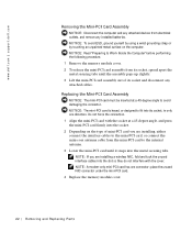
... keyed, or designed to Work Inside the Computer" before performing the following procedure. 1 Remove the memory module cover. 2 To release the mini-PCI card assembly from its socket, spread apart the metal securing tabs until it snaps into its socket and disconnect any attached cables. place the unused NIC connector under the mini-PCI card. 4 Replace the memory module cover. 22 Removi ng and Replacing Parts...
... keyed, or designed to Work Inside the Computer" before performing the following procedure. 1 Remove the memory module cover. 2 To release the mini-PCI card assembly from its socket, spread apart the metal securing tabs until it snaps into its socket and disconnect any attached cables. place the unused NIC connector under the mini-PCI card. 4 Replace the memory module cover. 22 Removi ng and Replacing Parts...

Service Manual
Page 23
... devices from the holes labeled "circle K." 3 Turn the computer over and open the display. Removing and Repl aci ng Part s 23 NOTICE: To avoid ESD, ground yourself by using a wrist grounding strap or by touching an unpainted metal surface on the keyboard are fragile, easily dislodged, and time-consuming to Work Inside the Computer" before performing the following procedure. 1 Remove the hard drive. 2 Turn...
... devices from the holes labeled "circle K." 3 Turn the computer over and open the display. Removing and Repl aci ng Part s 23 NOTICE: To avoid ESD, ground yourself by using a wrist grounding strap or by touching an unpainted metal surface on the keyboard are fragile, easily dislodged, and time-consuming to Work Inside the Computer" before performing the following procedure. 1 Remove the hard drive. 2 Turn...

Service Manual
Page 47
... by using a wrist grounding strap or by touching an unpainted metal surface on the thermal cooling assembly. Removing and Repl aci ng Part s 47 NOTICE: To ensure maximum cooling for the microprocessor, do not touch) type I ZIF socket type II ZIF socket Removing the Microprocessor Module NOTICE: Disconnect the computer and any attached devices from electrical outlets, and remove any installed batteries. perpendicular...
... by using a wrist grounding strap or by touching an unpainted metal surface on the thermal cooling assembly. Removing and Repl aci ng Part s 47 NOTICE: To ensure maximum cooling for the microprocessor, do not touch) type I ZIF socket type II ZIF socket Removing the Microprocessor Module NOTICE: Disconnect the computer and any attached devices from electrical outlets, and remove any installed batteries. perpendicular...
Service Manual
Page 50
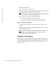
... shown in "Reserve Battery," contact Dell technical support. 4 Remove the reserve battery from the EMI shield: a Pry the reserve battery free from the foam pad. www.dell.com | support.dell.com 1 Remove the hard drive. 2 Remove the memory module cover. 3 Disconnect the reserve battery cable from the connector on the system board assembly located next to minimize slack in the cable. 3 Update the BIOS using a flash BIOS update program diskette or CD. Replacing the Reserve Battery 1 Connect the reserve battery cable to the connector...
... shown in "Reserve Battery," contact Dell technical support. 4 Remove the reserve battery from the EMI shield: a Pry the reserve battery free from the foam pad. www.dell.com | support.dell.com 1 Remove the hard drive. 2 Remove the memory module cover. 3 Disconnect the reserve battery cable from the connector on the system board assembly located next to minimize slack in the cable. 3 Update the BIOS using a flash BIOS update program diskette or CD. Replacing the Reserve Battery 1 Connect the reserve battery cable to the connector...
Service Manual
Page 56
... to enter the system's service tag number into the BIOS of the replacement system board assembly. 56 Removi ng and Replacing Parts a Insert the external microphone and headphone connectors through the plastic bottom case assembly. c Replace the fan guard cover, inserting the tab into the appropriate drive, and turn on the replacement system board. 2 Connect the right and left speaker to the replacement system board. 3 Install the replacement system board. Follow the instructions on...
... to enter the system's service tag number into the BIOS of the replacement system board assembly. 56 Removi ng and Replacing Parts a Insert the external microphone and headphone connectors through the plastic bottom case assembly. c Replace the fan guard cover, inserting the tab into the appropriate drive, and turn on the replacement system board. 2 Connect the right and left speaker to the replacement system board. 3 Install the replacement system board. Follow the instructions on...
System Information Guide
Page 4
...; Documentation updates, which are sometimes included with your computer to describe changes to your computer's back panel. Always read these options in all regions. • The User's Guide, which is an HTML document that are provided with any other Dell documents that includes descriptions of computer features, instructions on installing and configuring drivers and utilities, information on the System Setup program, and instructions for...
...; Documentation updates, which are sometimes included with your computer to describe changes to your computer's back panel. Always read these options in all regions. • The User's Guide, which is an HTML document that are provided with any other Dell documents that includes descriptions of computer features, instructions on installing and configuring drivers and utilities, information on the System Setup program, and instructions for...
System Information Guide
Page 5
... Latitude portable computer to operate with this computer. (Rev. 11/3/98) FILE LOCATION: D:\Eri_DProject\Dell\Temp\413CU0s\413CUeb0.fm Documents on the Web You can obtain the latest versions of any of the documents on your hard-disk drive as well as other troubleshooting information from burns. • Be sure that nothing rests on your adapter's power cable and that the cable...
... Latitude portable computer to operate with this computer. (Rev. 11/3/98) FILE LOCATION: D:\Eri_DProject\Dell\Temp\413CU0s\413CUeb0.fm Documents on the Web You can obtain the latest versions of any of the documents on your hard-disk drive as well as other troubleshooting information from burns. • Be sure that nothing rests on your adapter's power cable and that the cable...
System Information Guide
Page 6
... very warm during normal operation. connect the AC adapter from the electrical outlet. • If your computer includes an integrated or optional (PC Card) modem, the cable used batteries according to the manufacturers instructions or contact you local waste disposal agency for personal injury or shock. • If the computer is when you work, periodically touch the I/O panel to avoid the remote...
... very warm during normal operation. connect the AC adapter from the electrical outlet. • If your computer includes an integrated or optional (PC Card) modem, the cable used batteries according to the manufacturers instructions or contact you local waste disposal agency for personal injury or shock. • If the computer is when you work, periodically touch the I/O panel to avoid the remote...
System Information Guide
Page 8
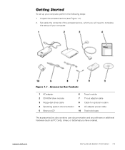
...) FILE LOCATION: D:\Eri_DProject\Dell\Temp\413CU0s\413CUeb0.fm Getting Started To set up your computer. Accessories Box Contents 1 AC adapter 2 CD-ROM drive module 3 Floppy-disk drive cable 4 Operating system documentation 5 ResourceCD 6 Travel module 7 TV-out adapter cable 8 Cable for optional modem 9 AC adapter power cable 10 Track stick caps The accessories box also contains user documentation and any software or additional hardware (such as PC Cards, drives, or batteries) you will need to complete the setup of...
...) FILE LOCATION: D:\Eri_DProject\Dell\Temp\413CU0s\413CUeb0.fm Getting Started To set up your computer. Accessories Box Contents 1 AC adapter 2 CD-ROM drive module 3 Floppy-disk drive cable 4 Operating system documentation 5 ResourceCD 6 Travel module 7 TV-out adapter cable 8 Cable for optional modem 9 AC adapter power cable 10 Track stick caps The accessories box also contains user documentation and any software or additional hardware (such as PC Cards, drives, or batteries) you will need to complete the setup of...
System Information Guide
Page 11
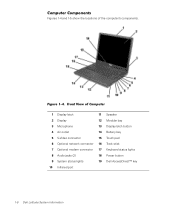
.... (Rev. 11/3/98) FILE LOCATION: D:\Eri_DProject\Dell\Temp\413CU0s\413CUeb0.fm Computer Components Figures 1-4 and 1-5 show the locations of Computer 1 Display latch 11 Speaker 2 Display 12 Modular bay 3 Microphone 13 Display latch button 4 Air outlet 14 Battery bay 5 S-Video connector 15 Touch pad 6 Optional network connector 16 Track stick 7 Optional modem connector 17 Keyboard status lights 8 Audio jacks (2) 18 Power button 9 System status lights 19 Dell AccessDirect™ key 10 Infrared port 1-8 Dell Latitude System Information Figure 1-4.
.... (Rev. 11/3/98) FILE LOCATION: D:\Eri_DProject\Dell\Temp\413CU0s\413CUeb0.fm Computer Components Figures 1-4 and 1-5 show the locations of Computer 1 Display latch 11 Speaker 2 Display 12 Modular bay 3 Microphone 13 Display latch button 4 Air outlet 14 Battery bay 5 S-Video connector 15 Touch pad 6 Optional network connector 16 Track stick 7 Optional modem connector 17 Keyboard status lights 8 Audio jacks (2) 18 Power button 9 System status lights 19 Dell AccessDirect™ key 10 Infrared port 1-8 Dell Latitude System Information Figure 1-4.
System Information Guide
Page 13
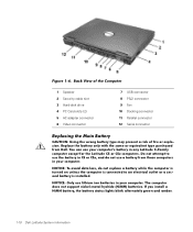
... Latitude C-Family computer except for the Latitude CS or CSx computers. NOTICE: Only use your computer. (Rev. 11/3/98) FILE LOCATION: D:\Eri_DProject\Dell\Temp\413CU0s\413CUeb0.fm Figure 1-6. Back View of the Computer 1 Speaker 2 Security cable slot 3 Hard-disk drive 4 PC Card slots (2) 5 AC adapter connector 6 Video connector 7 USB connector 8 PS/2 connector 9 Fan 10 Docking connector 11 Parallel connector 12 Serial connector Replacing the Main Battery CAUTION: Using the wrong battery type...
... Latitude C-Family computer except for the Latitude CS or CSx computers. NOTICE: Only use your computer. (Rev. 11/3/98) FILE LOCATION: D:\Eri_DProject\Dell\Temp\413CU0s\413CUeb0.fm Figure 1-6. Back View of the Computer 1 Speaker 2 Security cable slot 3 Hard-disk drive 4 PC Card slots (2) 5 AC adapter connector 6 Video connector 7 USB connector 8 PS/2 connector 9 Fan 10 Docking connector 11 Parallel connector 12 Serial connector Replacing the Main Battery CAUTION: Using the wrong battery type...
System Information Guide
Page 14
... Windows 95, Windows 98, or Windows NT, use suspend-to the side (see your work and close all open files and application programs. 2. The battery gauge will lose any unsaved data. • For Windows® 95, Windows 98, or Windows NT®, use hibernate mode. Place the computer in suspend mode by clicking the Start button, clicking Shut Down, and clicking Hibernate; When the green power indicator turns...
... Windows 95, Windows 98, or Windows NT, use suspend-to the side (see your work and close all open files and application programs. 2. The battery gauge will lose any unsaved data. • For Windows® 95, Windows 98, or Windows NT®, use hibernate mode. Place the computer in suspend mode by clicking the Start button, clicking Shut Down, and clicking Hibernate; When the green power indicator turns...
System Information Guide
Page 18
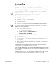
... docked. 3. When you want to access the system setup menu. To select an option from the CD-ROM drive. To start the Diagnostics, perform the following boot sequence: • Boot First Device: Diskette Drive • Boot Second Device: CD/DVD/CD-RW Drive • Boot Third Device: Internal HDD 6. Press at the start the diagnostics, the Dell logo screen appears, followed by a message telling you choose. To change the boot sequence, repeat steps 1 through...
... docked. 3. When you want to access the system setup menu. To select an option from the CD-ROM drive. To start the Diagnostics, perform the following boot sequence: • Boot First Device: Diskette Drive • Boot Second Device: CD/DVD/CD-RW Drive • Boot Third Device: Internal HDD 6. Press at the start the diagnostics, the Dell logo screen appears, followed by a message telling you choose. To change the boot sequence, repeat steps 1 through...


