

Installation Guide
Page 9
...P E N D I X INDEX Module Connectors B-17 RJ-45 Connector B-17 RJ-21 Connector B-18 RJ-21 Connector (WS-X6624-FXS Only) B-21 SC Connector B-22 MT-RJ Connector B-22 LC Connector B-23 Cables B-24 Console Port Mode Switch B-26 Identifying a Rollover Cable B-26 Console Port Mode 1 Signaling and Pinouts B-27 Console Port Mode 2 Signaling and... Pinouts B-28 Mode-Conditioning Patch Cord B-29 Cleaning the Fiber Optic Connectors B-31 Repacking the Switch C-1 Chassis and Module Power and Heat Values D-1 Troubleshooting E-1 Getting Started E-1 Solving Problems at the System Component Level ...
...P E N D I X INDEX Module Connectors B-17 RJ-45 Connector B-17 RJ-21 Connector B-18 RJ-21 Connector (WS-X6624-FXS Only) B-21 SC Connector B-22 MT-RJ Connector B-22 LC Connector B-23 Cables B-24 Console Port Mode Switch B-26 Identifying a Rollover Cable B-26 Console Port Mode 1 Signaling and Pinouts B-27 Console Port Mode 2 Signaling and... Pinouts B-28 Mode-Conditioning Patch Cord B-29 Cleaning the Fiber Optic Connectors B-31 Repacking the Switch C-1 Chassis and Module Power and Heat Values D-1 Troubleshooting E-1 Getting Started E-1 Solving Problems at the System Component Level ...
Installation Guide
Page 26
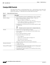
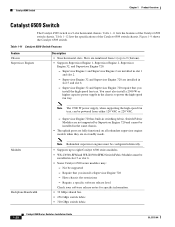
... identically. • Supports up to two Catalyst 6500 series modules. • Does not support the WS-C6500-SFM and WS-X6500-SFM2 Switch Fabric Modules. • Does not support the WS-X67xx modules. • Some Catalyst 6500 series modules may: - Catalyst 6503 Switch Chapter 1 Product Overview Catalyst 6503 Switch The Catalyst 6503 switch is a 3-slot horizontal chassis. Require a specific software release level Check...
... identically. • Supports up to two Catalyst 6500 series modules. • Does not support the WS-C6500-SFM and WS-X6500-SFM2 Switch Fabric Modules. • Does not support the WS-X67xx modules. • Some Catalyst 6500 series modules may: - Catalyst 6503 Switch Chapter 1 Product Overview Catalyst 6503 Switch The Catalyst 6503 switch is a 3-slot horizontal chassis. Require a specific software release level Check...

Installation Guide
Page 27
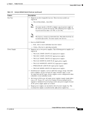
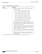
... four individual fans. Chapter 1 Product Overview Catalyst 6503 Switch Table 1-1 Catalyst 6503 Switch Features (continued) Feature Fan Tray Description • Supports one hot-swappable fan tray. OL-5781-04 Catalyst 6500 Series Switches Installation Guide 1-3 Required for Supervisor Engine 32 and Supervisor Engine 720. Green-Fan tray is not supported in the Catalyst 6503 chassis. • Fan tray STATUS LED - These fan tray models...
... four individual fans. Chapter 1 Product Overview Catalyst 6503 Switch Table 1-1 Catalyst 6503 Switch Features (continued) Feature Fan Tray Description • Supports one hot-swappable fan tray. OL-5781-04 Catalyst 6500 Series Switches Installation Guide 1-3 Required for Supervisor Engine 32 and Supervisor Engine 720. Green-Fan tray is not supported in the Catalyst 6503 chassis. • Fan tray STATUS LED - These fan tray models...
Installation Guide
Page 30
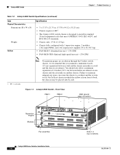
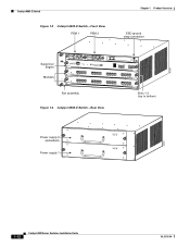
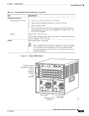
...). • Chassis fully configured with 1 supervisor engine, 2 modules, 2 AC-input PEMs, and 2 AC-input power supplies: 85.4 lb (38.7 kg). • FAN-MOD-3 (Standard fan tray)-170 CFM • FAN-MOD-3HS (Optional high-speed fan tray)-270 CFM 1. Figure 1-1 Catalyst 6503 Switch-Front View PEM 1 PEM 2 ESD ground strap connection 91239 Supervisor Engine Modules WS-X6K-SUP2...
...). • Chassis fully configured with 1 supervisor engine, 2 modules, 2 AC-input PEMs, and 2 AC-input power supplies: 85.4 lb (38.7 kg). • FAN-MOD-3 (Standard fan tray)-170 CFM • FAN-MOD-3HS (Optional high-speed fan tray)-270 CFM 1. Figure 1-1 Catalyst 6503 Switch-Front View PEM 1 PEM 2 ESD ground strap connection 91239 Supervisor Engine Modules WS-X6K-SUP2...
Installation Guide
Page 33
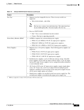
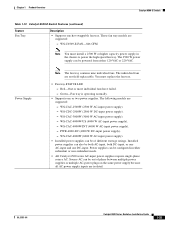
... must replace the fan tray. • Fan tray STATUS LED - Red-One or more individual fans have failed. Power supplies can be configured in the upper power supply bay. 1. Power Entry Module (PEM)1 - WS-C6503-E-FAN-282 CFM Note The fan tray contains four individual fans. Chapter 1 Product Overview Catalyst 6503-E Switch Table 1-3 Catalyst 6503-E Switch Features (continued) Feature Fan Tray Description...
... must replace the fan tray. • Fan tray STATUS LED - Red-One or more individual fans have failed. Power supplies can be configured in the upper power supply bay. 1. Power Entry Module (PEM)1 - WS-C6503-E-FAN-282 CFM Note The fan tray contains four individual fans. Chapter 1 Product Overview Catalyst 6503-E Switch Table 1-3 Catalyst 6503-E Switch Features (continued) Feature Fan Tray Description...
Installation Guide
Page 35
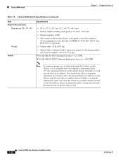
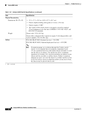
... PEMs, and 2 AC-input power supplies: 85.4 lb (38.7 kg). • WS-C6503-E-FAN-282 CFM 1. OL-5781-04 Catalyst 6500 Series Switches Installation Guide 1-11 On Catalyst chassis in which the airflow is designed to install in . (17.78 x 44.12 x 55.25 cm). • Chassis requires 4 RU1. • The Catalyst 6503-E switch chassis is from front to fail.
... PEMs, and 2 AC-input power supplies: 85.4 lb (38.7 kg). • WS-C6503-E-FAN-282 CFM 1. OL-5781-04 Catalyst 6500 Series Switches Installation Guide 1-11 On Catalyst chassis in which the airflow is designed to install in . (17.78 x 44.12 x 55.25 cm). • Chassis requires 4 RU1. • The Catalyst 6503-E switch chassis is from front to fail.
Installation Guide
Page 36
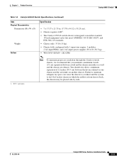
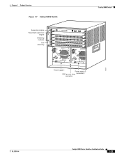
...Switch Figure 1-3 Catalyst 6503-E Switch-Front View PEM 1 PEM 2 Chapter 1 Product Overview ESD ground strap connection 91239 Supervisor Engine Modules WS-X6K-SUP2-2GE STATUS SYSTEMCONSOLPEWR MGRMETSET SUPERVISOR2 CONSOLE CONSOLE PORT MODE WS-X6516-GE-T X 16 PORT 1000 BASE-T GE WS-X6516-GE-T X 16 PORT 1000 BASE-T GE 1 2 3 4 LINK LINK LINK LINK 1 2 3 4 LINK LINK LINK LINK Fan... 1-4 Catalyst 6503-E Switch-Rear View 63031 Power supply 2 (redundant) Power supply 1 INPUT OK FAN OUTPUT OK FAIL INPUT FAN OUTPUT OK OK FAIL 1-12 Catalyst 6500 Series Switches Installation...
...Switch Figure 1-3 Catalyst 6503-E Switch-Front View PEM 1 PEM 2 Chapter 1 Product Overview ESD ground strap connection 91239 Supervisor Engine Modules WS-X6K-SUP2-2GE STATUS SYSTEMCONSOLPEWR MGRMETSET SUPERVISOR2 CONSOLE CONSOLE PORT MODE WS-X6516-GE-T X 16 PORT 1000 BASE-T GE WS-X6516-GE-T X 16 PORT 1000 BASE-T GE 1 2 3 4 LINK LINK LINK LINK 1 2 3 4 LINK LINK LINK LINK Fan... 1-4 Catalyst 6503-E Switch-Rear View 63031 Power supply 2 (redundant) Power supply 1 INPUT OK FAN OUTPUT OK FAIL INPUT FAN OUTPUT OK OK FAIL 1-12 Catalyst 6500 Series Switches Installation...
Installation Guide
Page 42
... Engine 720 require that you install the high-speed fan tray. Require that you install a Supervisor Engine 720 - Catalyst 6506 Switch Chapter 1 Product Overview Catalyst 6506 Switch The Catalyst 6506 switch is a 6-slot horizontal chassis. Supervisor Engine 720 has built-in standby mode. Table 1-8 lists the specifications of the Catalyst 6506 switch chassis. Slots are fully functional on the redundant supervisor...
... Engine 720 require that you install the high-speed fan tray. Require that you install a Supervisor Engine 720 - Catalyst 6506 Switch Chapter 1 Product Overview Catalyst 6506 Switch The Catalyst 6506 switch is a 6-slot horizontal chassis. Supervisor Engine 720 has built-in standby mode. Table 1-8 lists the specifications of the Catalyst 6506 switch chassis. Slots are fully functional on the redundant supervisor...
Installation Guide
Page 43
... to power the high-speed fan tray. Note The fan trays contains six individual fans. OL-5781-04 Catalyst 6500 Series Switches Installation Guide 1-19 You must install a 2500 W or higher capacity power supply in the chassis to the EOBC channel and the switching bus. • Three replaceable voltage termination (VTT) modules (WS-C6K-VTT=) provide reference voltage...
... to power the high-speed fan tray. Note The fan trays contains six individual fans. OL-5781-04 Catalyst 6500 Series Switches Installation Guide 1-19 You must install a 2500 W or higher capacity power supply in the chassis to the EOBC channel and the switching bus. • Three replaceable voltage termination (VTT) modules (WS-C6K-VTT=) provide reference voltage...
Installation Guide
Page 44
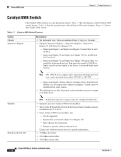
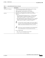
... in a Catalyst 6506 switch chassis, the 6000 W power supply has a maximum output of 4000 W. 1-20 Catalyst 6500 Series Switches Installation Guide OL-5781-04 Catalyst 6506 Switch Chapter 1 Product Overview Table 1-7 Catalyst 6506 Switch Features (continued) Feature Descriptions Power Supply • Supports one DC-input. WS-CAC-2500W ...the Supervisor Engine 720 and the high-speed fan tray. 1. Source AC can be out of different wattage ratings. WS-CAC-1300W (1300 W AC-input power supply). - WS-CAC-3000W (3000 W AC-input power supply). - WS-CAC-1000W (1000 W AC-input power ...
... in a Catalyst 6506 switch chassis, the 6000 W power supply has a maximum output of 4000 W. 1-20 Catalyst 6500 Series Switches Installation Guide OL-5781-04 Catalyst 6506 Switch Chapter 1 Product Overview Table 1-7 Catalyst 6506 Switch Features (continued) Feature Descriptions Power Supply • Supports one DC-input. WS-CAC-2500W ...the Supervisor Engine 720 and the high-speed fan tray. 1. Source AC can be out of different wattage ratings. WS-CAC-1300W (1300 W AC-input power supply). - WS-CAC-3000W (3000 W AC-input power supply). - WS-CAC-1000W (1000 W AC-input power ...
Installation Guide
Page 46
... including cable guide is 21.64 in. (55.0 cm). • Chassis requires 12 RU. • The Catalyst 6506 switch chassis is designed to install in which the airflow is from front to fail. WS-C6K-6SLOT-FAN (Standard fan tray)-227 CFM. On Catalyst chassis in standard 19-inch equipment racks that you maintain a minimum 6-inch (15 cm) separation...
... including cable guide is 21.64 in. (55.0 cm). • Chassis requires 12 RU. • The Catalyst 6506 switch chassis is designed to install in which the airflow is from front to fail. WS-C6K-6SLOT-FAN (Standard fan tray)-227 CFM. On Catalyst chassis in standard 19-inch equipment racks that you maintain a minimum 6-inch (15 cm) separation...
Installation Guide
Page 47
... Overview Figure 1-7 Catalyst 6506 Switch Supervisor engine Redundant supervisor engine Switching modules Fan assembly 1 2 3 4 FAN STATUS 5 6 WS-X6K-SUP2-2GE STATUS SYSTEMCONSOLPEWR MGRMETSET SUPERVISOR2 CONSOLE WS-X6K-SUP2-2GE STATUS SYSTEMCONSOLPEWR MGRMETSET SUPERVISOR2 CONSOLE CONSOLE PORT MODE CONSOLE PORT MODE WS-X6408 1 2 STATUS 8 PORT GIGABIT ETHERNET WS-X6408 1 2 8 PORT GIGABIT ETHERNET PCMCIA EJECT PCMCIA 3 EJECT 4 3 4 Switch Load 100% 1% Switch Load 100...
... Overview Figure 1-7 Catalyst 6506 Switch Supervisor engine Redundant supervisor engine Switching modules Fan assembly 1 2 3 4 FAN STATUS 5 6 WS-X6K-SUP2-2GE STATUS SYSTEMCONSOLPEWR MGRMETSET SUPERVISOR2 CONSOLE WS-X6K-SUP2-2GE STATUS SYSTEMCONSOLPEWR MGRMETSET SUPERVISOR2 CONSOLE CONSOLE PORT MODE CONSOLE PORT MODE WS-X6408 1 2 STATUS 8 PORT GIGABIT ETHERNET WS-X6408 1 2 8 PORT GIGABIT ETHERNET PCMCIA EJECT PCMCIA 3 EJECT 4 3 4 Switch Load 100% 1% Switch Load 100...
Installation Guide
Page 49
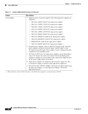
...1 Product Overview Catalyst 6506-E Switch Table 1-9 Catalyst 6506-E Switch Features (continued) Feature Fan Tray Descriptions • Supports one DC-input. Power Supply Note The fan tray contains six individual fans. WS-CAC-4000W-US (4000 W AC-input power supply). - WS-CAC-4000W-INT (4000 W AC-input power supply). - WS-CAC-6000W (..., both DC-input, or one AC-input and one hot-swappable fan tray. Green-Fan tray is installed in the chassis to power the fan tray. WS-CDC-2500W (2500 W DC-input power supply). - WS-CAC-2500W (2500 W AC-input power supply). - The 2500 ...
...1 Product Overview Catalyst 6506-E Switch Table 1-9 Catalyst 6506-E Switch Features (continued) Feature Fan Tray Descriptions • Supports one DC-input. Power Supply Note The fan tray contains six individual fans. WS-CAC-4000W-US (4000 W AC-input power supply). - WS-CAC-4000W-INT (4000 W AC-input power supply). - WS-CAC-6000W (..., both DC-input, or one AC-input and one hot-swappable fan tray. Green-Fan tray is installed in the chassis to power the fan tray. WS-CDC-2500W (2500 W DC-input power supply). - WS-CAC-2500W (2500 W AC-input power supply). - The 2500 ...
Installation Guide
Page 51
... Specification • 19.2 x 17.5 x 18.2 in. (48.8 x 44.5 x 46.0 cm). • Chassis depth including cable guide is designed to prevent overheating. Figure 1-8 Catalyst 6506-E Switch Supervisor engine Redundant supervisor engine Switching modules Fan assembly 1 2 3 4 FAN STATUS 5 6 WS-X6K-SUP2-2GE STATUS SYSTEMCONSOLPEWR MGRMETSET SUPERVISOR2 CONSOLE WS-X6K-SUP2-2GE STATUS SYSTEMCONSOLPEWR MGRMETSET SUPERVISOR2 CONSOLE CONSOLE PORT MODE CONSOLE...
... Specification • 19.2 x 17.5 x 18.2 in. (48.8 x 44.5 x 46.0 cm). • Chassis depth including cable guide is designed to prevent overheating. Figure 1-8 Catalyst 6506-E Switch Supervisor engine Redundant supervisor engine Switching modules Fan assembly 1 2 3 4 FAN STATUS 5 6 WS-X6K-SUP2-2GE STATUS SYSTEMCONSOLPEWR MGRMETSET SUPERVISOR2 CONSOLE WS-X6K-SUP2-2GE STATUS SYSTEMCONSOLPEWR MGRMETSET SUPERVISOR2 CONSOLE CONSOLE PORT MODE CONSOLE...
Installation Guide
Page 52
... VAC. - Figure 1-9 shows the Catalyst 6509 switch. Require that you install a Supervisor Engine 720 - Slots are installed in slot 5 or slot 6. • Some Catalyst 6500 series modules may: - You must be supported - Catalyst 6509 Switch Chapter 1 Product Overview Catalyst 6509 Switch The Catalyst 6509 switch is a 9-slot horizontal chassis. Table 1-12 lists the specifications of the Catalyst 6509 switch chassis. Table 1-11 Catalyst 6509 Switch Features Feature Chassis Supervisor Engines Description •...
... VAC. - Figure 1-9 shows the Catalyst 6509 switch. Require that you install a Supervisor Engine 720 - Slots are installed in slot 5 or slot 6. • Some Catalyst 6500 series modules may: - You must be supported - Catalyst 6509 Switch Chapter 1 Product Overview Catalyst 6509 Switch The Catalyst 6509 switch is a 9-slot horizontal chassis. Table 1-12 lists the specifications of the Catalyst 6509 switch chassis. Table 1-11 Catalyst 6509 Switch Features Feature Chassis Supervisor Engines Description •...

Installation Guide
Page 53
...chassis to the EOBC channel and the switching bus. • Three replaceable voltage termination (VTT) modules (WS-C6K-VTT=) provide reference voltage for Supervisor Engine 32 and Supervisor Engine 720. WS-C6K-9SLOT-FAN (Standard fan tray-340 CFM). These fan tray models are not field replaceable. WS...VAC. Red-One or more individual fans have failed. - Chapter 1 Product Overview Catalyst 6509 Switch Table 1-11 Catalyst 6509 Switch Features (continued) Feature Clock and VTT Modules Fan Tray Description • Two replaceable clock modules (WS-C6K-CL=) provide clocking signals to...
...chassis to the EOBC channel and the switching bus. • Three replaceable voltage termination (VTT) modules (WS-C6K-VTT=) provide reference voltage for Supervisor Engine 32 and Supervisor Engine 720. WS-C6K-9SLOT-FAN (Standard fan tray-340 CFM). These fan tray models are not field replaceable. WS...VAC. Red-One or more individual fans have failed. - Chapter 1 Product Overview Catalyst 6509 Switch Table 1-11 Catalyst 6509 Switch Features (continued) Feature Clock and VTT Modules Fan Tray Description • Two replaceable clock modules (WS-C6K-CL=) provide clocking signals to...
Installation Guide
Page 54
...Power supplies can also be configured in a Catalyst 6509 switch chassis, the 6000 W power supply has a maximum output of different wattage ratings. PWR-4000-DC (4000 W DC-input power supply). - WS-CAC-4000W-US (4000 W AC-input ...Catalyst 6509 Switch Features (continued) Feature Description Power Supply • Supports one DC-input. The following power supply models are installed in the right power supply bay. • You must install a 2500 W or higher capacity power supply when using the Supervisor Engine 32 or the Supervisor Engine 720 and the high-speed fan tray. 1. WS...
...Power supplies can also be configured in a Catalyst 6509 switch chassis, the 6000 W power supply has a maximum output of different wattage ratings. PWR-4000-DC (4000 W DC-input power supply). - WS-CAC-4000W-US (4000 W AC-input ...Catalyst 6509 Switch Features (continued) Feature Description Power Supply • Supports one DC-input. The following power supply models are installed in the right power supply bay. • You must install a 2500 W or higher capacity power supply when using the Supervisor Engine 32 or the Supervisor Engine 720 and the high-speed fan tray. 1. WS...
Installation Guide
Page 56
... the Catalyst switch chassis, we recommend that meet ANSI/EIA 310-D, IEC 60297, and ETS 300-119 standards. On Catalyst chassis in standard 19-inch equipment racks that you maintain a minimum 6-inch (15 cm) separation between the hot air exhaust on one chassis and the air intake on another chassis. WS-C6K-9SLOT-FAN (Standard fan tray)-340 CFM WS-C6K...
... the Catalyst switch chassis, we recommend that meet ANSI/EIA 310-D, IEC 60297, and ETS 300-119 standards. On Catalyst chassis in standard 19-inch equipment racks that you maintain a minimum 6-inch (15 cm) separation between the hot air exhaust on one chassis and the air intake on another chassis. WS-C6K-9SLOT-FAN (Standard fan tray)-340 CFM WS-C6K...

Installation Guide
Page 57
Chapter 1 Product Overview Figure 1-9 Catalyst 6509 Switch Catalyst 6509 Switch Supervisor engine Redundant supervisor engine Switching modules Fan assembly 1 2 3 4 5 6 7 8 FAN STATUS 9 WS-X6K-SUP2-2GE STATUS SYSTEMCONSOLPEWR MGRMETSET SUPERVISOR2 CONSOLE CONSOLE PORT MODE WS-X6K-SUP2-2GE STATUS SYSTEMCONSOLPEWR MGRMETSET SUPERVISOR2 CONSOLE CONSOLE PORT MODE WS-X6408 1 2 STATUS LINK 8 PORT GIGABIT ETHERNET WS-X6408 1 2 STATUS LINK 8 PORT GIGABIT ETHERNET WS-X6408 1 2 8 PORT GIGABIT ETHERNET LINK...
Chapter 1 Product Overview Figure 1-9 Catalyst 6509 Switch Catalyst 6509 Switch Supervisor engine Redundant supervisor engine Switching modules Fan assembly 1 2 3 4 5 6 7 8 FAN STATUS 9 WS-X6K-SUP2-2GE STATUS SYSTEMCONSOLPEWR MGRMETSET SUPERVISOR2 CONSOLE CONSOLE PORT MODE WS-X6K-SUP2-2GE STATUS SYSTEMCONSOLPEWR MGRMETSET SUPERVISOR2 CONSOLE CONSOLE PORT MODE WS-X6408 1 2 STATUS LINK 8 PORT GIGABIT ETHERNET WS-X6408 1 2 STATUS LINK 8 PORT GIGABIT ETHERNET WS-X6408 1 2 8 PORT GIGABIT ETHERNET LINK...
Installation Guide
Page 59
...either redundant or non-redundant mode. • All Catalyst 6500 series AC-input power supplies require single-phase source AC. Source AC can be configured in the chassis to power the high-speed fan tray. The 2500 W power supply can be of...- WS-CAC-2500W (2500 W AC-input power supply). - WS-CAC-4000W-INT (4000 W AC-input power supply). - WS-CAC-6000W (6000 W AC-input power supply). • Installed power supplies can be out of different wattage ratings. Chapter 1 Product Overview Catalyst 6509-E Switch Table 1-13 Catalyst 6509-E Switch Features (continued) Feature Fan Tray...
...either redundant or non-redundant mode. • All Catalyst 6500 series AC-input power supplies require single-phase source AC. Source AC can be configured in the chassis to power the high-speed fan tray. The 2500 W power supply can be of...- WS-CAC-2500W (2500 W AC-input power supply). - WS-CAC-4000W-INT (4000 W AC-input power supply). - WS-CAC-6000W (6000 W AC-input power supply). • Installed power supplies can be out of different wattage ratings. Chapter 1 Product Overview Catalyst 6509-E Switch Table 1-13 Catalyst 6509-E Switch Features (continued) Feature Fan Tray...


