
Installation Guide
Page 7
...E R Installing the Cable Management System (Catalyst 6509-NEB-A Switch Only) 3-23 Replacing the Cable Guide 3-25 Establishing the System Ground 3-27 Required Tools and Parts 3-28 Connecting the System Ground 3-29 Installing the Power Supplies in the Switch Chassis 3-34 Attaching the Interface Cables 3-34 ...Installing the Fan Assembly 4-57 Required Tools 4-57 Removing the Fan Assembly 4-57 Installing the Fan Assembly 4-65 Checking the Installation 4-65 Installing the Air Filter Assembly on a Catalyst 6509-NEB-A Switch (Optional) 4-66 OL-5781-04 Catalyst 6500 Series Switches Installation Guide...
...E R Installing the Cable Management System (Catalyst 6509-NEB-A Switch Only) 3-23 Replacing the Cable Guide 3-25 Establishing the System Ground 3-27 Required Tools and Parts 3-28 Connecting the System Ground 3-29 Installing the Power Supplies in the Switch Chassis 3-34 Attaching the Interface Cables 3-34 ...Installing the Fan Assembly 4-57 Required Tools 4-57 Removing the Fan Assembly 4-57 Installing the Fan Assembly 4-65 Checking the Installation 4-65 Installing the Air Filter Assembly on a Catalyst 6509-NEB-A Switch (Optional) 4-66 OL-5781-04 Catalyst 6500 Series Switches Installation Guide...

Installation Guide
Page 64
... Guide OL-5781-04 This kit must replace the fan tray. • Fan tray STATUS LED - If you are operating the chassis from this front panel DC power connector through a power harness also provided in the Catalyst 6509-NEB switch. Red-One or more individual fans have failed. - Green-Fan tray is a part of the upgrade kit). does not...
... Guide OL-5781-04 This kit must replace the fan tray. • Fan tray STATUS LED - If you are operating the chassis from this front panel DC power connector through a power harness also provided in the Catalyst 6509-NEB switch. Red-One or more individual fans have failed. - Green-Fan tray is a part of the upgrade kit). does not...
Installation Guide
Page 67
...; The Catalyst 6509-NEB switch chassis is designed to install in which the airflow is from front to fail. Chassis fully configured with 1 supervisor engine, 8 switching modules, and 2 power supplies: 135 lb (61.2 kg). • WS-C6509-NEB-FAN (Standard fan tray)-294 CFM • Optional high-speed fan tray2-630 CFM Note To maintain proper air circulation through the Catalyst switch chassis, we...
...; The Catalyst 6509-NEB switch chassis is designed to install in which the airflow is from front to fail. Chassis fully configured with 1 supervisor engine, 8 switching modules, and 2 power supplies: 135 lb (61.2 kg). • WS-C6509-NEB-FAN (Standard fan tray)-294 CFM • Optional high-speed fan tray2-630 CFM Note To maintain proper air circulation through the Catalyst switch chassis, we...

Installation Guide
Page 68
...Supervisor engine Redundant supervisor engine Slots 1-9 (right to left) 30695 Power supply 2 (redundant) FAN OUTPUT OK FAIL INPUT OK connection ESD ground strap WS-X6K-SUP2-2GE STATUSSYSTEMCONSOLPEWR MGRMETSET SUPERVISOR2 ...6 LINK 6 LINK 7 LINK 7 LINK 7 LINK PORT 2 LINK PORT 2 LINK 8 LINK 8 LINK 8 LINK FAN OUTPUT OK FAIL o o Catalyst 6500 Series Switches Installation Guide Power supply 1 INPUT OK Catalyst 6509-NEB Switch Figure 1-11 Catalyst 6509-NEB Switch Switching modules FAN STATUS Fan assembly WS-X6224 1 2 3 4 5 6 7 8 9 10 11 12 13 14 15 16 17 18 19...
...Supervisor engine Redundant supervisor engine Slots 1-9 (right to left) 30695 Power supply 2 (redundant) FAN OUTPUT OK FAIL INPUT OK connection ESD ground strap WS-X6K-SUP2-2GE STATUSSYSTEMCONSOLPEWR MGRMETSET SUPERVISOR2 ...6 LINK 6 LINK 7 LINK 7 LINK 7 LINK PORT 2 LINK PORT 2 LINK 8 LINK 8 LINK 8 LINK FAN OUTPUT OK FAIL o o Catalyst 6500 Series Switches Installation Guide Power supply 1 INPUT OK Catalyst 6509-NEB Switch Figure 1-11 Catalyst 6509-NEB Switch Switching modules FAN STATUS Fan assembly WS-X6224 1 2 3 4 5 6 7 8 9 10 11 12 13 14 15 16 17 18 19...

Installation Guide
Page 70
...same power supply because all AC power supply inputs are not field replaceable. The individual fans are isolated. 1-46 Catalyst 6500 Series Switches Installation Guide OL-5781-04 The following models are supported: - PWR-4000-DC (...Catalyst 6500 series AC-input power supplies require single-phase source AC. WS-CAC-6000W (6000 W AC-input power supply). • Installed power supplies can be out of different ratings. These fan tray models are supported: - Catalyst 6509-NEB-A Switch Chapter 1 Product Overview Table 1-17 Catalyst 6509-NEB-A Switch Features (continued) Feature Fan...
...same power supply because all AC power supply inputs are not field replaceable. The individual fans are isolated. 1-46 Catalyst 6500 Series Switches Installation Guide OL-5781-04 The following models are supported: - PWR-4000-DC (...Catalyst 6500 series AC-input power supplies require single-phase source AC. WS-CAC-6000W (6000 W AC-input power supply). • Installed power supplies can be out of different ratings. These fan tray models are supported: - Catalyst 6509-NEB-A Switch Chapter 1 Product Overview Table 1-17 Catalyst 6509-NEB-A Switch Features (continued) Feature Fan...
Installation Guide
Page 72
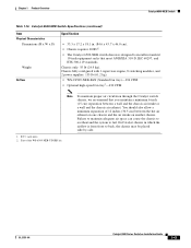
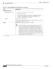
... be placed side-by-side. 1-48 Catalyst 6500 Series Switches Installation Guide OL-5781-04 Catalyst 6509-NEB-A Switch Chapter 1 Product Overview Table 1-18 Catalyst 6509-NEB-A Switch Specifications (continued) Item Physical Characteristics Dimensions (H x W x D) Weight Airflow Specification • 36.7 x 17.2 x 20.3 in. (93.1 x 43.7 x 51.6 cm). • Chassis requires 21 RU1. • The Catalyst 6509-NEB-A switch chassis is designed to install in which the airflow...
... be placed side-by-side. 1-48 Catalyst 6500 Series Switches Installation Guide OL-5781-04 Catalyst 6509-NEB-A Switch Chapter 1 Product Overview Table 1-18 Catalyst 6509-NEB-A Switch Specifications (continued) Item Physical Characteristics Dimensions (H x W x D) Weight Airflow Specification • 36.7 x 17.2 x 20.3 in. (93.1 x 43.7 x 51.6 cm). • Chassis requires 21 RU1. • The Catalyst 6509-NEB-A switch chassis is designed to install in which the airflow...

Installation Guide
Page 73
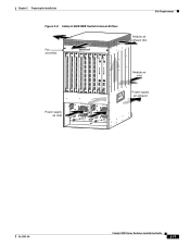
1-49 Catalyst 6500 Series Switches Installation Guide Catalyst 6509-NEB-A Switch Supervisor engine Redundant supervisor engine 79894 Power supply 2 (redundant) FAN OUTPUT OK FAIL INPUT OK ESD ground strap connection POWER SUPPLY 2 FAN OUTPUT OK FAIL o o SELECT STATUS ACTIVE NEXT INPUT OK SELECT STATUS ACTIVE Power supply 1 NEXT POWER SUPPLY 1 Chapter 1 Product Overview Figure 1-12 Catalyst 6509-NEB-A Switch Chassis WS-X6K-SUP2-2GE...
1-49 Catalyst 6500 Series Switches Installation Guide Catalyst 6509-NEB-A Switch Supervisor engine Redundant supervisor engine 79894 Power supply 2 (redundant) FAN OUTPUT OK FAIL INPUT OK ESD ground strap connection POWER SUPPLY 2 FAN OUTPUT OK FAIL o o SELECT STATUS ACTIVE NEXT INPUT OK SELECT STATUS ACTIVE Power supply 1 NEXT POWER SUPPLY 1 Chapter 1 Product Overview Figure 1-12 Catalyst 6509-NEB-A Switch Chassis WS-X6K-SUP2-2GE...

Installation Guide
Page 91
...-FAN2 (high speed) Catalyst 6506-E WS-6506-E-FAN WS-C6K-6SLOT-FAN WS-C6K-6SLOT-FAN2 (high speed) Catalyst 6509 WS-C6K-9SLOT-FAN WS-6509-E-FAN WS-C6K-9SLOT-FAN2 (high speed) Catalyst 6509-E WS-6509-E-FAN WS-C6K-9SLOT-FAN WS-C6K-9SLOT-FAN2 (high speed) Catalyst 6509-NEB WS-C6509-NEB-FAN - WS-6509-NEB-UPGRD1 (high speed) Catalyst 6509-NEB-A FAN-MOD-09 - Your Catalyst 6500 series switches currently installed in the...
...-FAN2 (high speed) Catalyst 6506-E WS-6506-E-FAN WS-C6K-6SLOT-FAN WS-C6K-6SLOT-FAN2 (high speed) Catalyst 6509 WS-C6K-9SLOT-FAN WS-6509-E-FAN WS-C6K-9SLOT-FAN2 (high speed) Catalyst 6509-E WS-6509-E-FAN WS-C6K-9SLOT-FAN WS-C6K-9SLOT-FAN2 (high speed) Catalyst 6509-NEB WS-C6509-NEB-FAN - WS-6509-NEB-UPGRD1 (high speed) Catalyst 6509-NEB-A FAN-MOD-09 - Your Catalyst 6500 series switches currently installed in the...
Installation Guide
Page 97
... for Installation Figure 2-8 Catalyst 6509-NEB Switch Internal Airflow WS-X6408 WS-X6K-SUP2-2GE STATUSSYSTEMCONSOLPEWR MGRMETSET SUPERVISOR2 WS-X6K-SUP2-2GE STATUSSYSTEMCONSOLPEWR MGRMETSET SUPERVISOR2 1 CONSOLE CONSOLE CONSOLE PORT MODE CONSOLE PORT MODE 2 3 Fan assembly FAN STATUS 8 PORT GIGABIT ... 5 LINK LINK 5 LINK 6 LINK LINK 6 LINK 7 LINK LINK 7 LINK 8 LINK LINK 8 LINK PCMCIA PCMCIA 4 EJECT EJECT 5 Switch Load 100% 1% Switch Load 100% 1% 6 PORT 1 LINK PORT 1 LINK 7 PORT 2 LINK PORT 2 LINK 8 Site Requirements Module air exhaust (3x) Module...
... for Installation Figure 2-8 Catalyst 6509-NEB Switch Internal Airflow WS-X6408 WS-X6K-SUP2-2GE STATUSSYSTEMCONSOLPEWR MGRMETSET SUPERVISOR2 WS-X6K-SUP2-2GE STATUSSYSTEMCONSOLPEWR MGRMETSET SUPERVISOR2 1 CONSOLE CONSOLE CONSOLE PORT MODE CONSOLE PORT MODE 2 3 Fan assembly FAN STATUS 8 PORT GIGABIT ... 5 LINK LINK 5 LINK 6 LINK LINK 6 LINK 7 LINK LINK 7 LINK 8 LINK LINK 8 LINK PCMCIA PCMCIA 4 EJECT EJECT 5 Switch Load 100% 1% Switch Load 100% 1% 6 PORT 1 LINK PORT 1 LINK 7 PORT 2 LINK PORT 2 LINK 8 Site Requirements Module air exhaust (3x) Module...

Installation Guide
Page 98
...-04 Chapter 2 Preparing for Installation Power supply air exhaust 79895 FAN OUTPUT OK FAIL INPUT OK POWER SUPPLY 2 FAN OUTPUT OK FAIL o o SELECT STATUS ACTIVE NEXT INPUT OK SELECT STATUS ACTIVE Catalyst 6500 Series Switches Installation Guide POWER SUPPLY 1 NEXT Site Requirements Figure 2-9 Catalyst 6509-NEB-A Switch Internal Airflow Module air exhaust WS-X6K-SUP2-2GE STATUSSYSTEMCONSOLPEWR MGRMETSET...
...-04 Chapter 2 Preparing for Installation Power supply air exhaust 79895 FAN OUTPUT OK FAIL INPUT OK POWER SUPPLY 2 FAN OUTPUT OK FAIL o o SELECT STATUS ACTIVE NEXT INPUT OK SELECT STATUS ACTIVE Catalyst 6500 Series Switches Installation Guide POWER SUPPLY 1 NEXT Site Requirements Figure 2-9 Catalyst 6509-NEB-A Switch Internal Airflow Module air exhaust WS-X6K-SUP2-2GE STATUSSYSTEMCONSOLPEWR MGRMETSET...

Installation Guide
Page 115
... 22 LINK 23 LINK 24 LINK 12 x 24 or 10 x 32 (10x) Cable guide o o INPUT OK FAN OUTPUT OK FAIL INPUT OK FAN OUTPUT OK FAIL 113976 Installing the L Brackets and Cable Guides on the Catalyst 6509-NEB Switch Note The Catalyst 6509-NEB switch chassis is normally shipped with ten M4 Phillips countersunk-head screws (five screws on each side).
... 22 LINK 23 LINK 24 LINK 12 x 24 or 10 x 32 (10x) Cable guide o o INPUT OK FAN OUTPUT OK FAIL INPUT OK FAN OUTPUT OK FAIL 113976 Installing the L Brackets and Cable Guides on the Catalyst 6509-NEB Switch Note The Catalyst 6509-NEB switch chassis is normally shipped with ten M4 Phillips countersunk-head screws (five screws on each side).

Installation Guide
Page 116
...the cable guide with five M4 screws. Figure 3-7 Attaching L Brackets and Cable Guides: Catalyst 6509-NEB Switch L bracket L bracket WS-X6408 WS-X6K-SUP2-2GE STATUSSYSTEMCONSOLPEWR MGRMETSET SUPERVISOR2 WS-X6K-SUP2-...MGRMETSET SUPERVISOR2 1 CONSOLE CONSOLE CONSOLE PORT MODE CONSOLE PORT MODE 2 3 PCMCIA PCMCIA FAN STATUS 8 PORT GIGABIT ETHERNET WS-X6408 8 PORT GIGABIT ETHERNET WS-X6408 8 ... holes.) Secure the L bracket to the switch chassis with four M4 screws. Installing the Rack-Mount Kit Chapter 3 Installing the Switch The optional cable guide installs on the front...
...the cable guide with five M4 screws. Figure 3-7 Attaching L Brackets and Cable Guides: Catalyst 6509-NEB Switch L bracket L bracket WS-X6408 WS-X6K-SUP2-2GE STATUSSYSTEMCONSOLPEWR MGRMETSET SUPERVISOR2 WS-X6K-SUP2-...MGRMETSET SUPERVISOR2 1 CONSOLE CONSOLE CONSOLE PORT MODE CONSOLE PORT MODE 2 3 PCMCIA PCMCIA FAN STATUS 8 PORT GIGABIT ETHERNET WS-X6408 8 PORT GIGABIT ETHERNET WS-X6408 8 ... holes.) Secure the L bracket to the switch chassis with four M4 screws. Installing the Rack-Mount Kit Chapter 3 Installing the Switch The optional cable guide installs on the front...

Installation Guide
Page 117
These brackets can be installed on Catalyst 6509-NEB-A Switch Step 1 Remove the screws that were removed in Step 1. L bracket FAN OUTPUT OK FAIL INPUT OK POWER SUPPLY 2 FAN OUTPUT OK FAIL o o SELECT STATUS ACTIVE NEXT Figure 3-8 Brackets on the rear of the chassis, perform these steps: Installing the Rack-Mount Kit 79896 WS-X6K-SUP2-2GE STATUSSYSTEMCONSOLPEWR...
These brackets can be installed on Catalyst 6509-NEB-A Switch Step 1 Remove the screws that were removed in Step 1. L bracket FAN OUTPUT OK FAIL INPUT OK POWER SUPPLY 2 FAN OUTPUT OK FAIL o o SELECT STATUS ACTIVE NEXT Figure 3-8 Brackets on the rear of the chassis, perform these steps: Installing the Rack-Mount Kit 79896 WS-X6K-SUP2-2GE STATUSSYSTEMCONSOLPEWR...
Installation Guide
Page 122
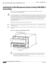
...MM STATUS 8 PORT OC3 POS FAN STATUS FAN 1 FAN 2 STAT STATUS Hinge screws Note To route the cables through the cable guide, remove the front panel, and attach the interface cables to the chassis. Assure that you install the cable... the chassis, as shown in Figure 3-11, and tighten the captive installation screws. Installing the Cable Management System (Catalyst 6509-NEB-A Switch Only) Chapter 3 Installing the Switch Installing the Cable Management System (Catalyst 6509-NEB-A Switch Only) This section describes the installation procedures for the Catalyst 6509-NEB-A switch cable ...
...MM STATUS 8 PORT OC3 POS FAN STATUS FAN 1 FAN 2 STAT STATUS Hinge screws Note To route the cables through the cable guide, remove the front panel, and attach the interface cables to the chassis. Assure that you install the cable... the chassis, as shown in Figure 3-11, and tighten the captive installation screws. Installing the Cable Management System (Catalyst 6509-NEB-A Switch Only) Chapter 3 Installing the Switch Installing the Cable Management System (Catalyst 6509-NEB-A Switch Only) This section describes the installation procedures for the Catalyst 6509-NEB-A switch cable ...

Installation Guide
Page 123
..., and route the cables through the cable guide. Chapter 3 Installing the Switch Installing the Cable Management System (Catalyst 6509-NEB-A Switch Only) Step 3 Loosen the two captive installation screws on the front panel. (See Figure 3-12.) Figure 3-12 Removing the Front Panel 99970 FAN STATUS FAN 1 FAN 2 STAT STATUS WS-X6K-SUP2-2GE STATUSSYSTEM SUPERVISOR2 WS-X6K-SUP2...
..., and route the cables through the cable guide. Chapter 3 Installing the Switch Installing the Cable Management System (Catalyst 6509-NEB-A Switch Only) Step 3 Loosen the two captive installation screws on the front panel. (See Figure 3-12.) Figure 3-12 Removing the Front Panel 99970 FAN STATUS FAN 1 FAN 2 STAT STATUS WS-X6K-SUP2-2GE STATUSSYSTEM SUPERVISOR2 WS-X6K-SUP2...

Installation Guide
Page 124
...Catalyst 6509-NEB-A Switch Only) Chapter 3 Installing the Switch Replacing the Cable Guide To replace the cable guides on the cable management system, perform these steps: Step 1 Loosen the two captive installation screws on the front panel. (See Figure 3-13.) Figure 3-13 Removing the Front Panel 99970 FAN STATUS FAN 1 FAN...from the back panel. (See Figure 3-14.) Figure 3-14 Removing the Cable Guide 85431 FAN STATUS FAN 1 FAN 2 STAT STATUS 3-20 Catalyst 6500 Series Switches Installation Guide WS-X6K-SUP2-2GE STATUSSYSTEM SUPERVISOR2 WS-X6K-SUP2-2GE STATUSSYSTEM SUPERVISOR2 OSM-40C12-...
...Catalyst 6509-NEB-A Switch Only) Chapter 3 Installing the Switch Replacing the Cable Guide To replace the cable guides on the cable management system, perform these steps: Step 1 Loosen the two captive installation screws on the front panel. (See Figure 3-13.) Figure 3-13 Removing the Front Panel 99970 FAN STATUS FAN 1 FAN...from the back panel. (See Figure 3-14.) Figure 3-14 Removing the Cable Guide 85431 FAN STATUS FAN 1 FAN 2 STAT STATUS 3-20 Catalyst 6500 Series Switches Installation Guide WS-X6K-SUP2-2GE STATUSSYSTEM SUPERVISOR2 WS-X6K-SUP2-2GE STATUSSYSTEM SUPERVISOR2 OSM-40C12-...

Installation Guide
Page 125
...guide. Install the front panel by hooking the lip of the front panel over the cable guide. Chapter 3 Installing the Switch Installing the Cable Management System (Catalyst 6509-NEB-A Switch Only) Step 4 Step 5 Install the standard cable guide to the back panel by hooking the top of the cable ...-SFM SWITCH FABRIC MDL WS-C6500-SFM SWITCH FABRIC MDL OSM-40C12-POS-MM STATUS OC12 POS MM OSM-8OC3-POS MM STATUS 8 PORT OC3 POS MM OSM-8OC3-POS MM STATUS 8 PORT OC3 POS FAN STATUS FAN 1 FAN 2 STAT STATUS Captive installation screws OL-5781-04 Catalyst 6500 Series Switches Installation...
...guide. Install the front panel by hooking the lip of the front panel over the cable guide. Chapter 3 Installing the Switch Installing the Cable Management System (Catalyst 6509-NEB-A Switch Only) Step 4 Step 5 Install the standard cable guide to the back panel by hooking the top of the cable ...-SFM SWITCH FABRIC MDL WS-C6500-SFM SWITCH FABRIC MDL OSM-40C12-POS-MM STATUS OC12 POS MM OSM-8OC3-POS MM STATUS 8 PORT OC3 POS MM OSM-8OC3-POS MM STATUS 8 PORT OC3 POS FAN STATUS FAN 1 FAN 2 STAT STATUS Captive installation screws OL-5781-04 Catalyst 6500 Series Switches Installation...

Installation Guide
Page 129
... System Ground Location (Catalyst 6506, Catalyst 6509, and Catalyst 6509-NEB Chassis) 32672 1 2 3 4 FAN 5 STATUS 6 WS-X6K-SUP2-2GE STATUS SYSTEMCONSOLPEWR MGRMETSET SUPERVISOR2 CONSOLE WS-X6K-SUP2-2GE STATUS SYSTEMCONSOLPEWR MGRMETSET SUPERVISOR2 CONSOLE WS-X6408 1 CONSOLE PORT MODE CONSOLE PORT MODE 2 STATUS 8 PORT GIGABIT ETHERNET WS-X6408 1 2 8 PORT GIGABIT ETHERNET PCMCIA EJECT PCMCIA 3 EJECT 4 3 4 Switch Load 100% 1% Switch Load 100...
... System Ground Location (Catalyst 6506, Catalyst 6509, and Catalyst 6509-NEB Chassis) 32672 1 2 3 4 FAN 5 STATUS 6 WS-X6K-SUP2-2GE STATUS SYSTEMCONSOLPEWR MGRMETSET SUPERVISOR2 CONSOLE WS-X6K-SUP2-2GE STATUS SYSTEMCONSOLPEWR MGRMETSET SUPERVISOR2 CONSOLE WS-X6408 1 CONSOLE PORT MODE CONSOLE PORT MODE 2 STATUS 8 PORT GIGABIT ETHERNET WS-X6408 1 2 8 PORT GIGABIT ETHERNET PCMCIA EJECT PCMCIA 3 EJECT 4 3 4 Switch Load 100% 1% Switch Load 100...

Installation Guide
Page 131
... OK Figure 3-20 System Ground Location (Catalyst 6509-NEB-A) System ground connector 113678 POWER SUPPLY 2 FAN OUTPUT OK FAIL o o SELECT System ground connectors Grounding lug WS-X6K-SUP2-2GE STATUSSYSTEMCONSOLPEWR MGRMETSET CONSOLE SUPERVISOR2 CONSOLE PORT MODE PCMCIA EJECT LINK Switch Load 100% 1% PORT 1 LINK PORT...-MM LINK 1 3 LINK 2 4 LINK 3 STATUS OC12 POS MM WS-C6500-SFM 1 2 LINK 1 3 LINK 2 4 LINK 3 PCMCIA EJECT Switch Load 100% 1% PORT 1 LINK PORT 2 LINK ACTIVE RX TX TX ACTIVE RX TX TX ACTIVE RX TX TX ACTIVE RX TX TX RESET CAARLRAIREMR RX...
... OK Figure 3-20 System Ground Location (Catalyst 6509-NEB-A) System ground connector 113678 POWER SUPPLY 2 FAN OUTPUT OK FAIL o o SELECT System ground connectors Grounding lug WS-X6K-SUP2-2GE STATUSSYSTEMCONSOLPEWR MGRMETSET CONSOLE SUPERVISOR2 CONSOLE PORT MODE PCMCIA EJECT LINK Switch Load 100% 1% PORT 1 LINK PORT...-MM LINK 1 3 LINK 2 4 LINK 3 STATUS OC12 POS MM WS-C6500-SFM 1 2 LINK 1 3 LINK 2 4 LINK 3 PCMCIA EJECT Switch Load 100% 1% PORT 1 LINK PORT 2 LINK ACTIVE RX TX TX ACTIVE RX TX TX ACTIVE RX TX TX ACTIVE RX TX TX RESET CAARLRAIREMR RX...
Installation Guide
Page 308
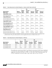
Table D-2 Power Requirements and Heat Dissipation-IP Phones Model Number/ Module Type Cisco IP Phone 7960 Cisco IP Phone 7940 Cisco IP Phone 7910 Module Module Power Current (A) (Watts) 0.15 6.3 0.15 6.3 0.13 5.46 AC AC-Input Power (Watts) 7.88 7.88 6.83 ...Watts) AC-Input Power (Watts) DC-Input Heat Diss. The Catalyst 6509-NEB-A switch chassis ships with two fan trays are double the values listed. Catalyst 6500 Series Switches Installation Guide D-2 OL-5781-04 The power and heat numbers for a chassis equipped with one fan tray installed by default. Each module has DC-to-DC power...
Table D-2 Power Requirements and Heat Dissipation-IP Phones Model Number/ Module Type Cisco IP Phone 7960 Cisco IP Phone 7940 Cisco IP Phone 7910 Module Module Power Current (A) (Watts) 0.15 6.3 0.15 6.3 0.13 5.46 AC AC-Input Power (Watts) 7.88 7.88 6.83 ...Watts) AC-Input Power (Watts) DC-Input Heat Diss. The Catalyst 6509-NEB-A switch chassis ships with two fan trays are double the values listed. Catalyst 6500 Series Switches Installation Guide D-2 OL-5781-04 The power and heat numbers for a chassis equipped with one fan tray installed by default. Each module has DC-to-DC power...