
Installation Guide
Page 7
...T E R Installing the Cable Management System (Catalyst 6509-NEB-A Switch Only) 3-23 Replacing the Cable Guide 3-25 Establishing the System Ground 3-27 Required Tools and Parts 3-28 Connecting the System Ground 3-29 Installing the Power Supplies in the Switch Chassis 3-34 Attaching the Interface Cables 3-34 Connecting the Supervisor Engine Console Port 3-34 Connecting the Supervisor Engine Uplink Ports 3-36 Verifying Switch Chassis Installation 3-41 Online Diagnostics 3-42 Removal and Replacement Procedures 4-1 Removing and Installing the AC-Input Power Supplies 4-2 Removing and Installing the...
...T E R Installing the Cable Management System (Catalyst 6509-NEB-A Switch Only) 3-23 Replacing the Cable Guide 3-25 Establishing the System Ground 3-27 Required Tools and Parts 3-28 Connecting the System Ground 3-29 Installing the Power Supplies in the Switch Chassis 3-34 Attaching the Interface Cables 3-34 Connecting the Supervisor Engine Console Port 3-34 Connecting the Supervisor Engine Uplink Ports 3-36 Verifying Switch Chassis Installation 3-41 Online Diagnostics 3-42 Removal and Replacement Procedures 4-1 Removing and Installing the AC-Input Power Supplies 4-2 Removing and Installing the...
Installation Guide
Page 22
... Assistance For all tools on the Cisco Technical Support Website requires a Cisco.com user ID and password. or for troubleshooting and resolving technical issues with the serial number label location highlighted. Catalyst 6500 Series Switches Installation Guide xxii OL-5781-04 If you have a valid service contract but do not have a user ID or password, you do not have Internet access, contact the Cisco TAC by copying and pasting...
... Assistance For all tools on the Cisco Technical Support Website requires a Cisco.com user ID and password. or for troubleshooting and resolving technical issues with the serial number label location highlighted. Catalyst 6500 Series Switches Installation Guide xxii OL-5781-04 If you have a valid service contract but do not have a user ID or password, you do not have Internet access, contact the Cisco TAC by copying and pasting...
Installation Guide
Page 49
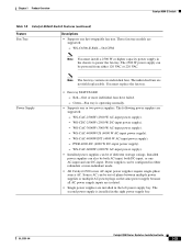
... must replace the fan tray. • Fan tray STATUS LED - You must install a 2500 W or higher capacity power supply in the left power supply bay. OL-5781-04 Catalyst 6500 Series Switches Installation Guide 1-25 The individual fans are supported: - Red-One or more individual fans have failed. - PWR-4000-DC (4000 W DC-input power supply). - These fan tray models are installed in the chassis to power the fan tray. Installed power supplies can also be out of different wattage ratings. Power Supply...
... must replace the fan tray. • Fan tray STATUS LED - You must install a 2500 W or higher capacity power supply in the left power supply bay. OL-5781-04 Catalyst 6500 Series Switches Installation Guide 1-25 The individual fans are supported: - Red-One or more individual fans have failed. - PWR-4000-DC (4000 W DC-input power supply). - These fan tray models are installed in the chassis to power the fan tray. Installed power supplies can also be out of different wattage ratings. Power Supply...
Installation Guide
Page 59
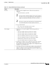
... W AC-input power supply). • Installed power supplies can be of phase between multiple power supplies or multiple AC-power plugs on the same power supply because all AC power supply inputs are supported: - The following models are isolated. Power supplies can be configured in the chassis to power the high-speed fan tray. WS-CAC-4000W-INT (4000 W AC-input power supply). - WS-CDC-2500W (2500 W DC-input power supply). - Chapter 1 Product Overview Catalyst 6509-E Switch Table 1-13 Catalyst 6509-E Switch Features (continued...
... W AC-input power supply). • Installed power supplies can be of phase between multiple power supplies or multiple AC-power plugs on the same power supply because all AC power supply inputs are supported: - The following models are isolated. Power supplies can be configured in the chassis to power the high-speed fan tray. WS-CAC-4000W-INT (4000 W AC-input power supply). - WS-CDC-2500W (2500 W DC-input power supply). - Chapter 1 Product Overview Catalyst 6509-E Switch Table 1-13 Catalyst 6509-E Switch Features (continued...

Installation Guide
Page 73
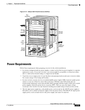
1-49 Catalyst 6500 Series Switches Installation Guide Catalyst 6509-NEB-A Switch Supervisor engine Redundant supervisor engine 79894 Power supply 2 (redundant) FAN OUTPUT OK FAIL INPUT OK ESD ground strap connection POWER SUPPLY 2 FAN OUTPUT OK FAIL o o SELECT STATUS ACTIVE NEXT INPUT OK SELECT STATUS ACTIVE Power supply 1 NEXT POWER SUPPLY 1 Chapter 1 Product Overview Figure 1-12 Catalyst 6509-NEB-A Switch Chassis WS-X6K-SUP2-2GE STATUSSYSTEMCONSOLPEWR MGRMETSET CONSOLE SUPERVISOR2 CONSOLE PORT MODE PCMCIA EJECT LINK Switch Load 100% 1% PORT 1 LINK PORT 2 WS-X6K-...
1-49 Catalyst 6500 Series Switches Installation Guide Catalyst 6509-NEB-A Switch Supervisor engine Redundant supervisor engine 79894 Power supply 2 (redundant) FAN OUTPUT OK FAIL INPUT OK ESD ground strap connection POWER SUPPLY 2 FAN OUTPUT OK FAIL o o SELECT STATUS ACTIVE NEXT INPUT OK SELECT STATUS ACTIVE Power supply 1 NEXT POWER SUPPLY 1 Chapter 1 Product Overview Figure 1-12 Catalyst 6509-NEB-A Switch Chassis WS-X6K-SUP2-2GE STATUSSYSTEMCONSOLPEWR MGRMETSET CONSOLE SUPERVISOR2 CONSOLE PORT MODE PCMCIA EJECT LINK Switch Load 100% 1% PORT 1 LINK PORT 2 WS-X6K-...
Installation Guide
Page 82
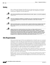
... access to maintain. A restricted access area can be accessed only through the use of a special tool, lock and key, or other means of your Catalyst 6500 series switch. Planning a proper location for the switch and layout of security. You should be aware of the switch chassis. 6-1 Catalyst 6500 Series Switches Installation Guide 2-2 OL-5781-04 This guide contains important safety information you should be allowed to install, replace, or service...
... access to maintain. A restricted access area can be accessed only through the use of a special tool, lock and key, or other means of your Catalyst 6500 series switch. Planning a proper location for the switch and layout of security. You should be aware of the switch chassis. 6-1 Catalyst 6500 Series Switches Installation Guide 2-2 OL-5781-04 This guide contains important safety information you should be allowed to install, replace, or service...
Installation Guide
Page 92
... right. 3. Figure 2-2 Catalyst 6503 and Catalyst 6503-E Switch Internal Airflow Module air exhaust WS-X6K-SUP2-2GE 1 STATUS SYSTEMCONSOLPEWR MGRMETSET SUPERVISOR2 CONSOLE CONSOLE PORT MODE PCMCIA EJECT OSM-4OC12 POS-SI 2 1 STATUS 2 4 PORT OC-12 POS SM IR LINK 1 2 LINK 3 4 LINK 3 4 LINK RESET ACTIVE TX RX CARARLIEARRM RX TX PORT 1 ACTIVE TX RX CARARLIEARRM RX TX PORT 2 OSM-4OC12 POS-SI 3 1 STATUS 2 4 PORT OC-12 POS SM IR LINK 1 2 LINK 3 4 LINK 3 4 LINK RESET ACTIVE TX...
... right. 3. Figure 2-2 Catalyst 6503 and Catalyst 6503-E Switch Internal Airflow Module air exhaust WS-X6K-SUP2-2GE 1 STATUS SYSTEMCONSOLPEWR MGRMETSET SUPERVISOR2 CONSOLE CONSOLE PORT MODE PCMCIA EJECT OSM-4OC12 POS-SI 2 1 STATUS 2 4 PORT OC-12 POS SM IR LINK 1 2 LINK 3 4 LINK 3 4 LINK RESET ACTIVE TX RX CARARLIEARRM RX TX PORT 1 ACTIVE TX RX CARARLIEARRM RX TX PORT 2 OSM-4OC12 POS-SI 3 1 STATUS 2 4 PORT OC-12 POS SM IR LINK 1 2 LINK 3 4 LINK 3 4 LINK RESET ACTIVE TX...
Installation Guide
Page 99
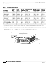
... current ratings of the two power supplies to the site power source. OL-5781-04 Catalyst 6500 Series Switches Installation Guide 2-19 Chapter 2 Preparing for Installation Figure 2-10 Catalyst 6513 Switch Internal Airflow Fan assembly Module air exhaust Fan status LED WS-X6K-SUP2-2GE 1 STATUS SYSTEMCONSOLPEWR MGRMETSET CONSOLE PORT SUPERVISOR2 CONSOLE MODE WS-X6K-SUP2-2GE 2 STATUS SYSTEMCONSOLPEWR MGRMETSET CONSOLE PORT SUPERVISOR2 CONSOLE MODE 3 PCMCIA EJECT PCMCIA EJECT Switch 100% Load 1% Switch 100% Load 1% PORT 1 LINK PORT 1 LINK PORT 2 LINK PORT 2 LINK...
... current ratings of the two power supplies to the site power source. OL-5781-04 Catalyst 6500 Series Switches Installation Guide 2-19 Chapter 2 Preparing for Installation Figure 2-10 Catalyst 6513 Switch Internal Airflow Fan assembly Module air exhaust Fan status LED WS-X6K-SUP2-2GE 1 STATUS SYSTEMCONSOLPEWR MGRMETSET CONSOLE PORT SUPERVISOR2 CONSOLE MODE WS-X6K-SUP2-2GE 2 STATUS SYSTEMCONSOLPEWR MGRMETSET CONSOLE PORT SUPERVISOR2 CONSOLE MODE 3 PCMCIA EJECT PCMCIA EJECT Switch 100% Load 1% Switch 100% Load 1% PORT 1 LINK PORT 1 LINK PORT 2 LINK PORT 2 LINK...
Installation Guide
Page 105
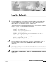
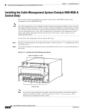
... Series Switches Installation Guide 3-1 For first-time installations, perform the procedures in the following sections in the order listed: • Unpacking the Switch, page 3-2 • Installing the Rack-Mount Kit, page 3-3 • Installing the Switch Chassis in the Rack, page 3-14 • Installing the Stabilizer Kit, page 3-16 • Installing the Cable Management System (Catalyst 6509-NEB-A Switch Only), page 3-18 • Establishing the System Ground, page 3-22 • Installing the Power Supplies in the Switch Chassis...
... Series Switches Installation Guide 3-1 For first-time installations, perform the procedures in the following sections in the order listed: • Unpacking the Switch, page 3-2 • Installing the Rack-Mount Kit, page 3-3 • Installing the Switch Chassis in the Rack, page 3-14 • Installing the Stabilizer Kit, page 3-16 • Installing the Cable Management System (Catalyst 6509-NEB-A Switch Only), page 3-18 • Establishing the System Ground, page 3-22 • Installing the Power Supplies in the Switch Chassis...

Installation Guide
Page 117
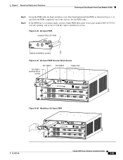
... the front of the brackets against the chassis side, and align the screw holes. 3-13 Catalyst 6500 Series Switches Installation Guide Position one of the chassis. L bracket FAN OUTPUT OK FAIL INPUT OK POWER SUPPLY 2 FAN OUTPUT OK FAIL o o SELECT STATUS ACTIVE NEXT Figure 3-8 Brackets on Catalyst 6509-NEB-A Switch Step 1 Remove the screws that secure the brackets to the chassis with the mounting brackets installed on the rear of the...
... the front of the brackets against the chassis side, and align the screw holes. 3-13 Catalyst 6500 Series Switches Installation Guide Position one of the chassis. L bracket FAN OUTPUT OK FAIL INPUT OK POWER SUPPLY 2 FAN OUTPUT OK FAIL o o SELECT STATUS ACTIVE NEXT Figure 3-8 Brackets on Catalyst 6509-NEB-A Switch Step 1 Remove the screws that secure the brackets to the chassis with the mounting brackets installed on the rear of the...
Installation Guide
Page 122
... FAN STATUS FAN 1 FAN 2 STAT STATUS Hinge screws Note To route the cables through the cable guide, remove the front panel, and attach the interface cables to 16 ports) using 10/100 cable. See the "Replacing the Cable Guide" section on attaching the interface cables. 3-18 Catalyst 6500 Series Switches Installation Guide OL-5781-04 Use the standard cable guide with the supplied standard cable guide. See the "Attaching the Interface Cables" section on page 3-28 for information on page 3-20 for the Catalyst 6509...
... FAN STATUS FAN 1 FAN 2 STAT STATUS Hinge screws Note To route the cables through the cable guide, remove the front panel, and attach the interface cables to 16 ports) using 10/100 cable. See the "Replacing the Cable Guide" section on attaching the interface cables. 3-18 Catalyst 6500 Series Switches Installation Guide OL-5781-04 Use the standard cable guide with the supplied standard cable guide. See the "Attaching the Interface Cables" section on page 3-28 for information on page 3-20 for the Catalyst 6509...

Installation Guide
Page 133
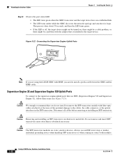
... adapter (labeled "Terminal"). Make sure there are no sharp bends in the cable guide (if installed). Position the cable in the cable. Check the terminal documentation to determine the baud rate. Set up the terminal as follows: • 9600 baud • 8 data bits • No parity • 2 stop bits To connect a terminal using a Catalyst 5000 family Supervisor Engine III console cable, follow these steps: Step 1 Step 2 Step 3 Step 4 Place the console port mode switch...
... adapter (labeled "Terminal"). Make sure there are no sharp bends in the cable guide (if installed). Position the cable in the cable. Check the terminal documentation to determine the baud rate. Set up the terminal as follows: • 9600 baud • 8 data bits • No parity • 2 stop bits To connect a terminal using a Catalyst 5000 family Supervisor Engine III console cable, follow these steps: Step 1 Step 2 Step 3 Step 4 Place the console port mode switch...
Installation Guide
Page 136
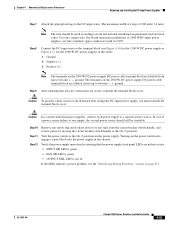
... the port status LED: • The LED turns green when the GBIC transceiver and the target device have an established link. • The LED turns amber while the GBIC discovers the network topology and searches for loops. Disconnect all cables before removing or installing an SFP transceiver. Do not remove and insert SFP transceivers more often than is installed in the target device. Figure 3-22 Connecting the Supervisor Engine Uplink Ports PORT 1 LINK...
... the port status LED: • The LED turns green when the GBIC transceiver and the target device have an established link. • The LED turns amber while the GBIC discovers the network topology and searches for loops. Disconnect all cables before removing or installing an SFP transceiver. Do not remove and insert SFP transceivers more often than is installed in the target device. Figure 3-22 Connecting the Supervisor Engine Uplink Ports PORT 1 LINK...
Installation Guide
Page 163
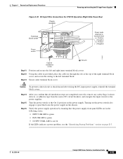
... Catalyst 6500 Series Switches Installation Guide 4-23 The maximum width of 2500 WDC-input power supplies, use fine-stranded copper conductors rated for the 2500 W DC power supply) in the chassis. Step 8 Connect the DC-input wires to bottom) -, +, ground. Note The wire should still be sized according to one supply, the second power source should be available. Ground 2. Positive (+) Note The terminals on the 2500 W DC power supply...
... Catalyst 6500 Series Switches Installation Guide 4-23 The maximum width of 2500 WDC-input power supplies, use fine-stranded copper conductors rated for the 2500 W DC power supply) in the chassis. Step 8 Connect the DC-input wires to bottom) -, +, ground. Note The wire should still be sized according to one supply, the second power source should be available. Ground 2. Positive (+) Note The terminals on the 2500 W DC power supply...
Installation Guide
Page 183
... Position and secure the left terminal block. Verify the power supply operation by ensuring that locks the power supply in the following states: • INPUT OK LED is green • FAN OK LED is green • OUTPUT FAIL LED is not lit If the LEDs indicate a power problem, see the "Identifying Startup Problems" section on the power supply. OL-5781-04 Catalyst 6500 Series Switches Installation Guide 4-43 Using the cable tie provided, place the...
... Position and secure the left terminal block. Verify the power supply operation by ensuring that locks the power supply in the following states: • INPUT OK LED is green • FAN OK LED is green • OUTPUT FAIL LED is not lit If the LEDs indicate a power problem, see the "Identifying Startup Problems" section on the power supply. OL-5781-04 Catalyst 6500 Series Switches Installation Guide 4-43 Using the cable tie provided, place the...
Installation Guide
Page 195
... PEM Catalyst 6503 DC PEM 79980 Captive installation screws Figure 4-45 DC-Input PEM Terminal Block Screws DC PEM 1 terminal block screws DC PEM 1 DC PEM 2 Cable clips WS-X6K-SUP2-2GE STATUS SYSTEMCONSOLPEWR MGRMETSET SUPERVISOR2 CONSOLE CONSOLE PORT MODE PCMCIA EJECT OSM-4OC12 POS-SI 1 STATUS 2 4 PORT OC-12 POS SM IR LINK 1 OSM-4OC12 POS-SI 1 STATUS 2 4 PORT OC-12 POS SM IR LINK 1 2 LINK 2 LINK 3 4 LINK 3 4 LINK RESET...
... PEM Catalyst 6503 DC PEM 79980 Captive installation screws Figure 4-45 DC-Input PEM Terminal Block Screws DC PEM 1 terminal block screws DC PEM 1 DC PEM 2 Cable clips WS-X6K-SUP2-2GE STATUS SYSTEMCONSOLPEWR MGRMETSET SUPERVISOR2 CONSOLE CONSOLE PORT MODE PCMCIA EJECT OSM-4OC12 POS-SI 1 STATUS 2 4 PORT OC-12 POS SM IR LINK 1 OSM-4OC12 POS-SI 1 STATUS 2 4 PORT OC-12 POS SM IR LINK 1 2 LINK 2 LINK 3 4 LINK 3 4 LINK RESET...
Installation Guide
Page 275
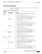
..., and Cable Specifications Transceivers 1-GB Transceiver Modules Table B-2 lists along with brief descriptions of compatible modules and the software release level necessary to cabling distances tables, and reference illustrations. OL-5781-04 Catalyst 6500 Series Switches Installation Guide B-3 Table B-2 1-GB Transceiver Modules Descriptions Transceiver Type GBIC Transceivers Product Number WS-G5483= WS-G5484= WS-G5486= WS-G5487= SFP GLC-T= Transceivers GLC-SX-MM= Description • 1000BASE-T GBIC transceiver module for copper networks...
..., and Cable Specifications Transceivers 1-GB Transceiver Modules Table B-2 lists along with brief descriptions of compatible modules and the software release level necessary to cabling distances tables, and reference illustrations. OL-5781-04 Catalyst 6500 Series Switches Installation Guide B-3 Table B-2 1-GB Transceiver Modules Descriptions Transceiver Type GBIC Transceivers Product Number WS-G5483= WS-G5484= WS-G5486= WS-G5487= SFP GLC-T= Transceivers GLC-SX-MM= Description • 1000BASE-T GBIC transceiver module for copper networks...
Installation Guide
Page 282
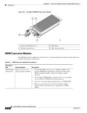
... appearance of a CWDM GBIC. • Refer to your release notes for Transceivers specific product numbers • The CWDM GBIC transceivers use with brief descriptions of modules and the software release level necessary to support these CWDM GBICs. Table B-7 WDM Transceiver Modules Descriptions Transceiver Type Product Number Description CWDM GBIC Refer to Table B-8 for a list of the transceiver modules and reference illustrations. B-10 Catalyst 6500 Series Switches Installation Guide OL-5781-04
... appearance of a CWDM GBIC. • Refer to your release notes for Transceivers specific product numbers • The CWDM GBIC transceivers use with brief descriptions of modules and the software release level necessary to support these CWDM GBICs. Table B-7 WDM Transceiver Modules Descriptions Transceiver Type Product Number Description CWDM GBIC Refer to Table B-8 for a list of the transceiver modules and reference illustrations. B-10 Catalyst 6500 Series Switches Installation Guide OL-5781-04
Installation Guide
Page 318
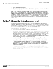
...: • Power supply-Includes the power supplies and power supply fans. • Fan assembly-The chassis fan assembly should see the FAN LED turn green and hear the fan assembly operating. Also, refer to troubleshoot the software: Catalyst 6500 Series Switch Software Configuration Guide, the Catalyst 6500 Series Switch Cisco IOS Software Configuration Guide, the Catalyst 6500 Series Switch Command Reference, or the Catalyst 6500 Series Switch Cisco IOS Command Reference. Catalyst 6500 Series Switches Installation Guide E-2 OL-5781-04 If all switching modules are installed properly in...
...: • Power supply-Includes the power supplies and power supply fans. • Fan assembly-The chassis fan assembly should see the FAN LED turn green and hear the fan assembly operating. Also, refer to troubleshoot the software: Catalyst 6500 Series Switch Software Configuration Guide, the Catalyst 6500 Series Switch Cisco IOS Software Configuration Guide, the Catalyst 6500 Series Switch Command Reference, or the Catalyst 6500 Series Switch Cisco IOS Command Reference. Catalyst 6500 Series Switches Installation Guide E-2 OL-5781-04 If all switching modules are installed properly in...
Installation Guide
Page 319
... the "Removing and Installing the Fan Assembly" section on each switching module are green when the supervisor engine completes initialization. Appendix E Troubleshooting Identifying Startup Problems Identifying Startup Problems LEDs indicate all chassis environmental monitors are reporting that the system is OK. If you can determine when and where the system failed in standby mode, the ACTIVE LED is orange. • Each LINK LED should turn green when the module is...
... the "Removing and Installing the Fan Assembly" section on each switching module are green when the supervisor engine completes initialization. Appendix E Troubleshooting Identifying Startup Problems Identifying Startup Problems LEDs indicate all chassis environmental monitors are reporting that the system is OK. If you can determine when and where the system failed in standby mode, the ACTIVE LED is orange. • Each LINK LED should turn green when the module is...


