
Installation Guide
Page 30
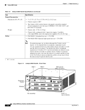
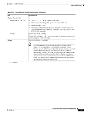
... Note To maintain proper air circulation through the Catalyst switch chassis, we recommend that meet ANSI/EIA 310-D, IEC 60297, and ETS 300-119 standards. • Chassis only: 27 lb (12.25 kg). • Chassis fully configured with 1 supervisor engine, 2 modules, 2 AC-input PEMs, and 2 AC-input power supplies: 85.4 lb (38.7 kg). • FAN-MOD-3 (Standard...
... Note To maintain proper air circulation through the Catalyst switch chassis, we recommend that meet ANSI/EIA 310-D, IEC 60297, and ETS 300-119 standards. • Chassis only: 27 lb (12.25 kg). • Chassis fully configured with 1 supervisor engine, 2 modules, 2 AC-input PEMs, and 2 AC-input power supplies: 85.4 lb (38.7 kg). • FAN-MOD-3 (Standard...
Installation Guide
Page 35
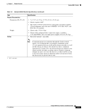
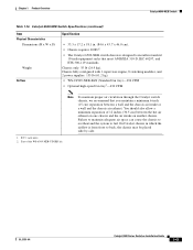
... wall and the chassis air intake or a wall and the chassis air exhaust. Failure to maintain adequate air space can cause the chassis to overheat and the system to back, the chassis may be placed side-by-side. On Catalyst chassis in which the airflow...119 standards. • Chassis only: 33 lb (15 kg). • Chassis fully configured with 1 supervisor engine, 2 modules, 2 AC-input PEMs, and 2 AC-input power supplies: 85.4 lb (38.7 kg). • WS-C6503-E-FAN-282 CFM 1. Chapter 1 Product Overview Catalyst 6503-E Switch Table 1-4 Catalyst 6503-E Switch Specifications (continued) Item ...
... wall and the chassis air intake or a wall and the chassis air exhaust. Failure to maintain adequate air space can cause the chassis to overheat and the system to back, the chassis may be placed side-by-side. On Catalyst chassis in which the airflow...119 standards. • Chassis only: 33 lb (15 kg). • Chassis fully configured with 1 supervisor engine, 2 modules, 2 AC-input PEMs, and 2 AC-input power supplies: 85.4 lb (38.7 kg). • WS-C6503-E-FAN-282 CFM 1. Chapter 1 Product Overview Catalyst 6503-E Switch Table 1-4 Catalyst 6503-E Switch Specifications (continued) Item ...
Installation Guide
Page 46
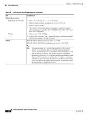
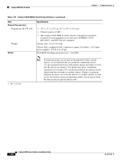
... air exhaust on one chassis and the air intake on another chassis. Note To maintain proper air circulation through the Catalyst switch chassis, we recommend that meet ANSI/EIA 310-D, IEC 60297, and ETS 300-119 standards. • Chassis only: 45 lb (20.4 kg). • Chassis fully configured with 1 supervisor engine, 5 switching modules, and 2 power supplies: 156.6 lb (71.0 kg...
... air exhaust on one chassis and the air intake on another chassis. Note To maintain proper air circulation through the Catalyst switch chassis, we recommend that meet ANSI/EIA 310-D, IEC 60297, and ETS 300-119 standards. • Chassis only: 45 lb (20.4 kg). • Chassis fully configured with 1 supervisor engine, 5 switching modules, and 2 power supplies: 156.6 lb (71.0 kg...
Installation Guide
Page 56
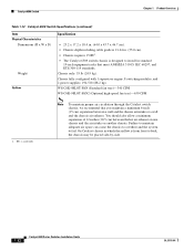
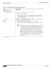
...-FAN2 (Optional high-speed fan tray)-630 CFM 1. On Catalyst chassis in which the airflow is designed to install in . (55.0 cm). • Chassis requires 15 RU1. • The Catalyst 6509 switch chassis is from front to fail. Chassis fully configured with 1 supervisor engine, 8 switching modules, and 2 power supplies: 194.5 lb (88.2 kg). Failure to maintain adequate air space can cause the...
...-FAN2 (Optional high-speed fan tray)-630 CFM 1. On Catalyst chassis in which the airflow is designed to install in . (55.0 cm). • Chassis requires 15 RU1. • The Catalyst 6509 switch chassis is from front to fail. Chassis fully configured with 1 supervisor engine, 8 switching modules, and 2 power supplies: 194.5 lb (88.2 kg). Failure to maintain adequate air space can cause the...
Installation Guide
Page 61
... cm) separation between the hot air exhaust on one chassis and the air intake on another chassis. Chassis fully configured with 1 supervisor engine, 8 switching modules, and 2 power supplies: 190 lb (86.4 kg). WS-C6509-E-FAN-846 CFM 1. RU = rack units Note To maintain proper air circulation through the Catalyst switch chassis, we recommend that meet ANSI/EIA 310-D, IEC...
... cm) separation between the hot air exhaust on one chassis and the air intake on another chassis. Chassis fully configured with 1 supervisor engine, 8 switching modules, and 2 power supplies: 190 lb (86.4 kg). WS-C6509-E-FAN-846 CFM 1. RU = rack units Note To maintain proper air circulation through the Catalyst switch chassis, we recommend that meet ANSI/EIA 310-D, IEC...
Installation Guide
Page 67
...43.7 x 46.0 cm). • Chassis requires 20 RU1. • The Catalyst 6509-NEB switch chassis is from front to back, the chassis may be placed side-by-side. 1. OL-5781-04 Catalyst 6500 Series Switches Installation Guide 1-43 Chassis fully configured with 1 supervisor engine, 8 switching modules, and 2 power supplies: 135 lb (61.2 kg). •...of the WS-6509-NEB-UPGRD kit. Chassis only: 55 lb (24.9 kg). Failure to maintain adequate air space can cause the chassis to overheat and the system to install in which the airflow is designed to fail. On Catalyst chassis in standard 19...
...43.7 x 46.0 cm). • Chassis requires 20 RU1. • The Catalyst 6509-NEB switch chassis is from front to back, the chassis may be placed side-by-side. 1. OL-5781-04 Catalyst 6500 Series Switches Installation Guide 1-43 Chassis fully configured with 1 supervisor engine, 8 switching modules, and 2 power supplies: 135 lb (61.2 kg). •...of the WS-6509-NEB-UPGRD kit. Chassis only: 55 lb (24.9 kg). Failure to maintain adequate air space can cause the chassis to overheat and the system to install in which the airflow is designed to fail. On Catalyst chassis in standard 19...
Installation Guide
Page 72
... power supplies: 270 lb (122.47 kg). Catalyst 6509-NEB-A Switch Chapter 1 Product Overview Table 1-18 Catalyst 6509-NEB-A Switch Specifications (continued) Item Physical Characteristics Dimensions (H x W x D) Weight Airflow Specification • 36.7 x 17.2 x 20.3 in. (93.1 x 43.7 x 51.6 cm). • Chassis requires 21 RU1. • The Catalyst 6509-NEB-A switch chassis is designed to install in which the airflow is from front to fail. Failure...
... power supplies: 270 lb (122.47 kg). Catalyst 6509-NEB-A Switch Chapter 1 Product Overview Table 1-18 Catalyst 6509-NEB-A Switch Specifications (continued) Item Physical Characteristics Dimensions (H x W x D) Weight Airflow Specification • 36.7 x 17.2 x 20.3 in. (93.1 x 43.7 x 51.6 cm). • Chassis requires 21 RU1. • The Catalyst 6509-NEB-A switch chassis is designed to install in which the airflow is from front to fail. Failure...
Installation Guide
Page 78
... exhaust on one chassis and the air intake on another chassis. Failure to maintain adequate air space can cause the chassis to overheat and the system to back, the chassis may be placed side-by-side. 1-54 Catalyst 6500 Series Switches Installation Guide OL-5781-04 Chassis fully configured with 2 supervisor engines, 11 switching modules, and 2 power supplies: 280 lb (127...
... exhaust on one chassis and the air intake on another chassis. Failure to maintain adequate air space can cause the chassis to overheat and the system to back, the chassis may be placed side-by-side. 1-54 Catalyst 6500 Series Switches Installation Guide OL-5781-04 Chassis fully configured with 2 supervisor engines, 11 switching modules, and 2 power supplies: 280 lb (127...
Installation Guide
Page 84
... the system. • Do not permit food or drink near the system. Catalyst 6500 Series Switches Installation Guide 2-4 OL-5781-04 Conversely, RFI from a person's fingers or prolonged...corrode the gold-plated edge connectors and pin connectors on the back of the chassis. • Always use shielded cables with metal connector shells for attaching peripherals...failures of dust and other particles, which act as insulators and interfere with the mechanical components in the system. Site Requirements Chapter 2 Preparing for Installation Dust and Particles Exhaust fans cool power supplies...
... the system. • Do not permit food or drink near the system. Catalyst 6500 Series Switches Installation Guide 2-4 OL-5781-04 Conversely, RFI from a person's fingers or prolonged...corrode the gold-plated edge connectors and pin connectors on the back of the chassis. • Always use shielded cables with metal connector shells for attaching peripherals...failures of dust and other particles, which act as insulators and interfere with the mechanical components in the system. Site Requirements Chapter 2 Preparing for Installation Dust and Particles Exhaust fans cool power supplies...

Installation Guide
Page 90
..., and power supplies. On Catalyst 6500 series chassis in which the airflow is a sufficient volume of overheating. - If the ambient intake air temperature equals or is insufficient airflow to stabilize (approximately 2 hours). To maintain proper air circulation through the Catalyst 6500 switch chassis, we ... the ambient air temperature within the chassis operating temperature limits. Failure to install your site meets the following guidelines: • Verify that you choose to maintain adequate spacing between the air intake of one chassis and the hot air exhaust of ...
..., and power supplies. On Catalyst 6500 series chassis in which the airflow is a sufficient volume of overheating. - If the ambient intake air temperature equals or is insufficient airflow to stabilize (approximately 2 hours). To maintain proper air circulation through the Catalyst 6500 switch chassis, we ... the ambient air temperature within the chassis operating temperature limits. Failure to install your site meets the following guidelines: • Verify that you choose to maintain adequate spacing between the air intake of one chassis and the hot air exhaust of ...
Installation Guide
Page 99
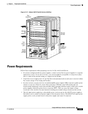
... unstable when operating with two power supplies, connect each power supply to protect against power failures at your site. Please be aware when selecting a UPS that allows you fail to do this, your system might be susceptible to total power failure due to a separate input power source. Chapter 2 Preparing for Installation Figure 2-10 Catalyst 6513 Switch Internal Airflow Fan assembly Module...
... unstable when operating with two power supplies, connect each power supply to protect against power failures at your site. Please be aware when selecting a UPS that allows you fail to do this, your system might be susceptible to total power failure due to a separate input power source. Chapter 2 Preparing for Installation Figure 2-10 Catalyst 6513 Switch Internal Airflow Fan assembly Module...
Installation Guide
Page 102
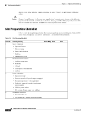
... on power supply)1 • Receptacle proximity to the module. Site Preparation Checklist Chapter 2 Preparing for power failures • DC systems: Proper gauge wire and lugs 4 Grounding evaluation: • Circuit breaker size • CO ground (AC- Site Preparation Checklist Table 2-4 lists the site planning activities that you should perform prior to installing the Catalyst 6500 series switch.
... on power supply)1 • Receptacle proximity to the module. Site Preparation Checklist Chapter 2 Preparing for power failures • DC systems: Proper gauge wire and lugs 4 Grounding evaluation: • Circuit breaker size • CO ground (AC- Site Preparation Checklist Table 2-4 lists the site planning activities that you should perform prior to installing the Catalyst 6500 series switch.
Installation Guide
Page 139
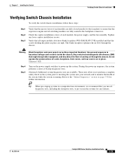
... optimize the air flow through the chassis. During the power-up the system. Refer to the "Online Diagnostics" section on the power supply switches to power up sequence, the system performs a series of bootup diagnostic tests. (Optional) Additional system diagnostic tests are tight. Tighten any failures. OL-5781-04 Catalyst 6500 Series Switches Installation Guide 3-35 Check the captive...
... optimize the air flow through the chassis. During the power-up the system. Refer to the "Online Diagnostics" section on the power supply switches to power up sequence, the system performs a series of bootup diagnostic tests. (Optional) Additional system diagnostic tests are tight. Tighten any failures. OL-5781-04 Catalyst 6500 Series Switches Installation Guide 3-35 Check the captive...
Installation Guide
Page 146
.... Caution In a system with redundant power supplies, you can replace the faulty supply while the system is present on page E-3 for troubleshooting information. Catalyst 6500 Series Switches Installation Guide 4-6 OL-5781-04 Removing and Installing the AC-Input Power Supplies Chapter 4 Removal and Replacement Procedures Step 6 Connect the other end of a power source failure, the second source should still...
.... Caution In a system with redundant power supplies, you can replace the faulty supply while the system is present on page E-3 for troubleshooting information. Catalyst 6500 Series Switches Installation Guide 4-6 OL-5781-04 Removing and Installing the AC-Input Power Supplies Chapter 4 Removal and Replacement Procedures Step 6 Connect the other end of a power source failure, the second source should still...
Installation Guide
Page 149
... page E-3 for troubleshooting information. Step 7 Connect the other end of a power source failure, the second source will most likely still be tight to remove and install the 1000 W, 1300 W, 2500 W, 3000 W, 4000 W, and 6000 W AC-input power supplies in the Catalyst 6500 series switches that the power supply LEDs are removed and installed using the same procedures. Chapter...
... page E-3 for troubleshooting information. Step 7 Connect the other end of a power source failure, the second source will most likely still be tight to remove and install the 1000 W, 1300 W, 2500 W, 3000 W, 4000 W, and 6000 W AC-input power supplies in the Catalyst 6500 series switches that the power supply LEDs are removed and installed using the same procedures. Chapter...
Installation Guide
Page 152
Slide the power supply into the power supply, and tighten the screw on the cable retention device. Switching the power switch to On also engages a pawl that locks the power supply in the bay. Step 8 Step 9 Turn the power switch to the On (|) position on page E-3 for troubleshooting information. 4-12 Catalyst 6500 Series Switches Installation Guide OL-5781-04 Verify the power supply operation by ensuring...
Slide the power supply into the power supply, and tighten the screw on the cable retention device. Switching the power switch to On also engages a pawl that locks the power supply in the bay. Step 8 Step 9 Turn the power switch to the On (|) position on page E-3 for troubleshooting information. 4-12 Catalyst 6500 Series Switches Installation Guide OL-5781-04 Verify the power supply operation by ensuring...
Installation Guide
Page 156
...sure that the chassis you are working on page E-3. 4-16 Catalyst 6500 Series Switches Installation Guide OL-5781-04 Note The system (NEBS) ground serves as shown in Figure 4-10. The DC-input power supplies for the Catalyst 6503 and Catalyst 6503-E chassis that you ...failure, the second source should still be tight to a separate input line. For ground connection installation instructions, see the "Identifying Startup Problems" section on the circuit. Step 5 Step 6 Step 7 Verify that service the DC circuits. To ensure that all connections to prevent accidental power...
...sure that the chassis you are working on page E-3. 4-16 Catalyst 6500 Series Switches Installation Guide OL-5781-04 Note The system (NEBS) ground serves as shown in Figure 4-10. The DC-input power supplies for the Catalyst 6503 and Catalyst 6503-E chassis that you ...failure, the second source should still be tight to a separate input line. For ground connection installation instructions, see the "Identifying Startup Problems" section on the circuit. Step 5 Step 6 Step 7 Verify that service the DC circuits. To ensure that all connections to prevent accidental power...
Installation Guide
Page 163
...; OUTPUT FAIL LED is 0.300 inch (7.6 mm). The terminals on page E-3. Caution In a system with dual power supplies, connect each power supply to the DC-input wires. OL-5781-04 Catalyst 6500 Series Switches Installation Guide 4-23 The maximum width of a lug is not lit If the LEDs indicate... Problems" section on the 2500 W DC power supply DC power cable terminal block are secure, reinstall the terminal block cover. In case of 2500 WDC-input power supplies, use fine-stranded copper conductors rated for the 2500 W DC power supply) in the chassis. Use only copper wire. Step 10 Step...
...; OUTPUT FAIL LED is 0.300 inch (7.6 mm). The terminals on page E-3. Caution In a system with dual power supplies, connect each power supply to the DC-input wires. OL-5781-04 Catalyst 6500 Series Switches Installation Guide 4-23 The maximum width of a lug is not lit If the LEDs indicate... Problems" section on the 2500 W DC power supply DC power cable terminal block are secure, reinstall the terminal block cover. In case of 2500 WDC-input power supplies, use fine-stranded copper conductors rated for the 2500 W DC power supply) in the chassis. Use only copper wire. Step 10 Step...

Installation Guide
Page 194
...with dual power supplies, connect each power supply to the On (|) position on the PEM. Removing the DC-Input PEM Warning Before performing any of the following procedures, ensure that power is ...power circuit breaker, or place a piece of the chassis so that you have access to the DC circuit for a list of supported AC power cords.) Step 6 Connect the other end of a power source failure...system ground connection. 4-54 Catalyst 6500 Series Switches Installation Guide OL-5781-04 Loosen the captive installation screws on the circuit. Step 7 Turn the power switch to a separate input source....
...with dual power supplies, connect each power supply to the On (|) position on the PEM. Removing the DC-Input PEM Warning Before performing any of the following procedures, ensure that power is ...power circuit breaker, or place a piece of the chassis so that you have access to the DC circuit for a list of supported AC power cords.) Step 6 Connect the other end of a power source failure...system ground connection. 4-54 Catalyst 6500 Series Switches Installation Guide OL-5781-04 Loosen the captive installation screws on the circuit. Step 7 Turn the power switch to a separate input source....

Installation Guide
Page 196
... failure, the second source will most likely still be made . Statement 1003 Warning When installing or replacing the unit, the ground connection must always be available. For ground connection installation instructions, see the "Identifying Startup Problems" section on page E-3. 4-56 Catalyst 6500 Series Switches Installation Guide OL-5781-04 Positive (+) After ensuring that power...
... failure, the second source will most likely still be made . Statement 1003 Warning When installing or replacing the unit, the ground connection must always be available. For ground connection installation instructions, see the "Identifying Startup Problems" section on page E-3. 4-56 Catalyst 6500 Series Switches Installation Guide OL-5781-04 Positive (+) After ensuring that power...

