
Installation Guide
Page 134
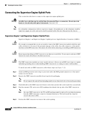
... identify the top side of the socket opening. 3-30 Catalyst 6500 Series Switches Installation Guide OL-5781-04 Disconnect all cables before removing or installing an SFP transceiver. To install and cable an GBIC transceiver, follow these steps (see Figure 3-22): Step...with modules. Step 5 Position the GBIC transceiver in the chassis. Do not remove and insert GBIC transceivers more often than is absolutely necessary. Always use Gigabit Interface Converters (GBICs). Attaching the Interface Cables Chapter 3 Installing the Switch Connecting the Supervisor Engine Uplink Ports This...
... identify the top side of the socket opening. 3-30 Catalyst 6500 Series Switches Installation Guide OL-5781-04 Disconnect all cables before removing or installing an SFP transceiver. To install and cable an GBIC transceiver, follow these steps (see Figure 3-22): Step...with modules. Step 5 Position the GBIC transceiver in the chassis. Do not remove and insert GBIC transceivers more often than is absolutely necessary. Always use Gigabit Interface Converters (GBICs). Attaching the Interface Cables Chapter 3 Installing the Switch Connecting the Supervisor Engine Uplink Ports This...
Installation Guide
Page 135
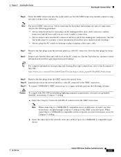
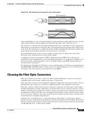
... grounded, shielded, twisted-pair, Category 5 cabling. OL-5781-04 Catalyst 6500 Series Switches Installation Guide 3-31 Inspect and clean the fiber-optic end-faces on a 1000BASE-T-compatible target device. To connect 1000BASE-T GBIC transceivers to a copper network, perform the following guidelines: • ... document at this URL: http://www.cisco.com/en/US/tech/tk482/tk607/technologies_white_paper09186a0080254eba.shtml Step 9 Step 10 Step 11 Remove the dust plugs from the network interface cable SC connectors. Note For optical GBIC transceivers, before making any connections. (...
... grounded, shielded, twisted-pair, Category 5 cabling. OL-5781-04 Catalyst 6500 Series Switches Installation Guide 3-31 Inspect and clean the fiber-optic end-faces on a 1000BASE-T-compatible target device. To connect 1000BASE-T GBIC transceivers to a copper network, perform the following guidelines: • ... document at this URL: http://www.cisco.com/en/US/tech/tk482/tk607/technologies_white_paper09186a0080254eba.shtml Step 9 Step 10 Step 11 Remove the dust plugs from the network interface cable SC connectors. Note For optical GBIC transceivers, before making any connections. (...
Installation Guide
Page 136
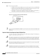
... in the SFP transceiver. Caution The SFP transceiver modules are using the LX/LH GBIC with MMF, you do not install or remove the SFP transceiver module with modules. 3-32 Catalyst 6500 Series Switches Installation Guide OL-5781-04 This process takes about 30 seconds, and then the ... all cables before removing or installing an SFP transceiver. Attaching the Interface Cables Chapter 3 Installing the Switch Step 12 Observe the port status LED: • The LED turns green when the GBIC transceiver and the target device have an established link. • The LED turns amber while the...
... in the SFP transceiver. Caution The SFP transceiver modules are using the LX/LH GBIC with MMF, you do not install or remove the SFP transceiver module with modules. 3-32 Catalyst 6500 Series Switches Installation Guide OL-5781-04 This process takes about 30 seconds, and then the ... all cables before removing or installing an SFP transceiver. Attaching the Interface Cables Chapter 3 Installing the Switch Step 12 Observe the port status LED: • The LED turns green when the GBIC transceiver and the target device have an established link. • The LED turns amber while the...
Installation Guide
Page 275
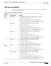
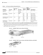
OL-5781-04 Catalyst 6500 Series Switches Installation Guide B-3 Appendix B Transceivers, Module Connectors, and Cable Specifications Transceivers 1-GB Transceiver Modules Table B-2 lists along with brief descriptions of the transceiver modules, ... contained in Table B-3. • Refer to your release notes for a list of compatible modules and the software release level necessary to support this GBIC. • 1000BASE-LX/LH GBIC transceiver module for SMF • 1300-nm wavelength • SC duplex connector. (See Figure B-3.) • Transceiver cabling information is contained in Table ...
OL-5781-04 Catalyst 6500 Series Switches Installation Guide B-3 Appendix B Transceivers, Module Connectors, and Cable Specifications Transceivers 1-GB Transceiver Modules Table B-2 lists along with brief descriptions of the transceiver modules, ... contained in Table B-3. • Refer to your release notes for a list of compatible modules and the software release level necessary to support this GBIC. • 1000BASE-LX/LH GBIC transceiver module for SMF • 1300-nm wavelength • SC duplex connector. (See Figure B-3.) • Transceiver cabling information is contained in Table ...
Installation Guide
Page 277
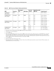
... install a mode-conditioning patch cord (CAB-GELX-625 or equivalent) between the GBIC and the MMF cable on fiber loss. 3. OL-5781-04 Catalyst 6500 Series Switches Installation Guide B-5 Appendix B Transceivers, Module Connectors, and Cable Specifications Transceivers Table B-3 GBIC Transceiver Module Cabling Specifications GBIC Connector Wavelength Core Size1 Modal Bandwidth (nm) Cable Type (micron) (MHz... ft (550 m) 50.0 500 1804 ft (550 m) 1000BASE-ZX5 (WS-G5487) SC duplex 1550 SMF G.652 - The mode-conditioning patch cord is required for ZX GBICs is 24.9 miles (40 km).
... install a mode-conditioning patch cord (CAB-GELX-625 or equivalent) between the GBIC and the MMF cable on fiber loss. 3. OL-5781-04 Catalyst 6500 Series Switches Installation Guide B-5 Appendix B Transceivers, Module Connectors, and Cable Specifications Transceivers Table B-3 GBIC Transceiver Module Cabling Specifications GBIC Connector Wavelength Core Size1 Modal Bandwidth (nm) Cable Type (micron) (MHz... ft (550 m) 50.0 500 1804 ft (550 m) 1000BASE-ZX5 (WS-G5487) SC duplex 1550 SMF G.652 - The mode-conditioning patch cord is required for ZX GBICs is 24.9 miles (40 km).
Installation Guide
Page 278
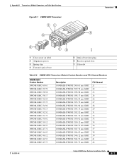
... 100 km)2 1. the distance depends on both the sending and receiving ends of splices, and the connectors. Figure B-2 1000BASE-T GBIC Transceiver Module (WS-G5483) 36494 49959 RJ-45 connector Plastic tab Figure B-3 1000BASE-X GBIC Transceiver Modules (WS-G5484, WS-G5486, and WS-G5487) Receiver Transmitter Catalyst 6500 Series Switches Installation Guide B-6 OL-5781-04
... 100 km)2 1. the distance depends on both the sending and receiving ends of splices, and the connectors. Figure B-2 1000BASE-T GBIC Transceiver Module (WS-G5483) 36494 49959 RJ-45 connector Plastic tab Figure B-3 1000BASE-X GBIC Transceiver Modules (WS-G5484, WS-G5486, and WS-G5487) Receiver Transmitter Catalyst 6500 Series Switches Installation Guide B-6 OL-5781-04
Installation Guide
Page 282
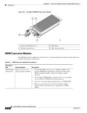
...specific product numbers • The CWDM GBIC transceivers use MMF and SMF cable to provide 1000BASE-X full-duplex connectivity between the GBIC-compatible modules, supervisor engines, and the network. • A set of eight CWDM GBICs, listed in Table B-7 along with brief... descriptions of modules and the software release level necessary to Table B-8 for a list of the transceiver modules and reference illustrations. B-10 Catalyst 6500 Series Switches...
...specific product numbers • The CWDM GBIC transceivers use MMF and SMF cable to provide 1000BASE-X full-duplex connectivity between the GBIC-compatible modules, supervisor engines, and the network. • A set of eight CWDM GBICs, listed in Table B-7 along with brief... descriptions of modules and the software release level necessary to Table B-8 for a list of the transceiver modules and reference illustrations. B-10 Catalyst 6500 Series Switches...
Installation Guide
Page 283
... • DWDM GBIC transceivers are used as a pluggable receiver on a port-by Cisco CWDM and DWDM transceivers and can connect the CWDM SFPs to CWDM passive optical system optical add/drop multiplexer (OADM) modules or multiplexer/demultiplexer plug-in a CWDM or DWDM transport network; OL-5781-04 Catalyst 6500 Series Switches Installation Guide B-11...
... • DWDM GBIC transceivers are used as a pluggable receiver on a port-by Cisco CWDM and DWDM transceivers and can connect the CWDM SFPs to CWDM passive optical system optical add/drop multiplexer (OADM) modules or multiplexer/demultiplexer plug-in a CWDM or DWDM transport network; OL-5781-04 Catalyst 6500 Series Switches Installation Guide B-11...
Installation Guide
Page 284
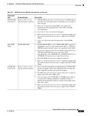
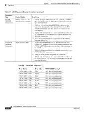
...• There are used as a pluggable receiver on any unidirectional link in the XENPAK. • The receiver can be used for all wavelengths supported by Cisco DWDM XENPAK transceivers. • The W/O WDM receiver has a single SC connector. • Refer to your release notes for a list of compatible modules... CWDM GBIC Wavelength 1470 nm laser single-mode 1490 nm laser single-mode 1510 nm laser single-mode 1530 nm laser single-mode 1550 nm laser single-mode 1570 nm laser single-mode 1590 nm laser single-mode 1610 nm laser single-mode B-12 Catalyst 6500 Series Switches Installation ...
...• There are used as a pluggable receiver on any unidirectional link in the XENPAK. • The receiver can be used for all wavelengths supported by Cisco DWDM XENPAK transceivers. • The W/O WDM receiver has a single SC connector. • Refer to your release notes for a list of compatible modules... CWDM GBIC Wavelength 1470 nm laser single-mode 1490 nm laser single-mode 1510 nm laser single-mode 1530 nm laser single-mode 1550 nm laser single-mode 1570 nm laser single-mode 1590 nm laser single-mode 1610 nm laser single-mode B-12 Catalyst 6500 Series Switches Installation ...
Installation Guide
Page 285
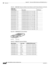
... GBIC 1000BASE-DWDM 1548.51 nm GBIC 1000BASE-DWDM 1547.72 nm GBIC 1000BASE-DWDM 1546.92 nm GBIC 1000BASE-DWDM 1546.12 nm GBIC 1000BASE-DWDM 1544.53 nm GBIC 1000BASE-DWDM 1543.73 nm GBIC ITU Channel 21 22 23 24 26 27 28 29 31 32 33 34 36 37 38 39 41 42 Catalyst... 6500 Series Switches Installation...
... GBIC 1000BASE-DWDM 1548.51 nm GBIC 1000BASE-DWDM 1547.72 nm GBIC 1000BASE-DWDM 1546.92 nm GBIC 1000BASE-DWDM 1546.12 nm GBIC 1000BASE-DWDM 1544.53 nm GBIC 1000BASE-DWDM 1543.73 nm GBIC ITU Channel 21 22 23 24 26 27 28 29 31 32 33 34 36 37 38 39 41 42 Catalyst... 6500 Series Switches Installation...
Installation Guide
Page 286
... Channel Numbers (continued) DWDM GBIC Product Number DWDM-GBIC-42.94 DWDM-GBIC-42.14 DWDM-GBIC-40.56 DWDM-GBIC-39.77 DWDM-GBIC-39.98 DWDM-GBIC-38.19 DWDM-GBIC-36.61 DWDM-GBIC-35.82 DWDM-GBIC-35.04 DWDM-GBIC-34.25 DWDM-GBIC-32.68 DWDM-GBIC-31.90 DWDM-GBIC-31.12 DWDM-GBIC-30.33 Description 1000BASE...-DWDM 1542.94 nm GBIC 1000BASE...
... Channel Numbers (continued) DWDM GBIC Product Number DWDM-GBIC-42.94 DWDM-GBIC-42.14 DWDM-GBIC-40.56 DWDM-GBIC-39.77 DWDM-GBIC-39.98 DWDM-GBIC-38.19 DWDM-GBIC-36.61 DWDM-GBIC-35.82 DWDM-GBIC-35.04 DWDM-GBIC-34.25 DWDM-GBIC-32.68 DWDM-GBIC-31.90 DWDM-GBIC-31.12 DWDM-GBIC-30.33 Description 1000BASE...-DWDM 1542.94 nm GBIC 1000BASE...
Installation Guide
Page 301
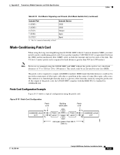
... the link. At the output of the patch cord, the LX/LH GBIC complies with 62.5-micron diameter MMF, you must install a mode-conditioning patch cord (Cisco product number CAB-GELX-625 or equivalent) between the GBIC and the multimode fiber (MMF) cable on both the transmit and receive ...BER). Note We do not recommend using the long wavelength/long-haul (LX/LH) GBIC with the IEEE 802.3z standard for link distances greater than 984 ft (300 m) 13088 OL-5781-04 Catalyst 6500 Series Switches Installation Guide B-29 The solution is required for 1000BASE-LX. Figure B-19 Patch Cord...
... the link. At the output of the patch cord, the LX/LH GBIC complies with 62.5-micron diameter MMF, you must install a mode-conditioning patch cord (Cisco product number CAB-GELX-625 or equivalent) between the GBIC and the multimode fiber (MMF) cable on both the transmit and receive ...BER). Note We do not recommend using the long wavelength/long-haul (LX/LH) GBIC with the IEEE 802.3z standard for link distances greater than 984 ft (300 m) 13088 OL-5781-04 Catalyst 6500 Series Switches Installation Guide B-29 The solution is required for 1000BASE-LX. Figure B-19 Patch Cord...
Installation Guide
Page 302
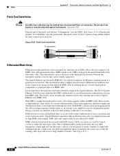
...3z Gigabit Ethernet Task Force has identified the DMD condition that occurs with certain combinations of the patch cord labeled "To Equipment" into the GBIC. (See Figure B-20.) Plug the end labeled "To Cable Plant" into the fiber-optic cable in the link span (the distance ...equipment To cable plant 13089 Differential Mode Delay When an unconditioned laser source designed for use of modes. (See Figure B-21.) B-30 Catalyst 6500 Series Switches Installation Guide OL-5781-04 These modes, or light pathways, then follow two or more different paths. These paths might occur. With DMD...
...3z Gigabit Ethernet Task Force has identified the DMD condition that occurs with certain combinations of the patch cord labeled "To Equipment" into the GBIC. (See Figure B-20.) Plug the end labeled "To Cable Plant" into the fiber-optic cable in the link span (the distance ...equipment To cable plant 13089 Differential Mode Delay When an unconditioned laser source designed for use of modes. (See Figure B-21.) B-30 Catalyst 6500 Series Switches Installation Guide OL-5781-04 These modes, or light pathways, then follow two or more different paths. These paths might occur. With DMD...
Installation Guide
Page 303
... cores meet. Connector loss, or insertion loss, is also an important factor. OL-5781-04 Catalyst 6500 Series Switches Installation Guide B-31 An unconditioned launch, in the worst case, might concentrate all uplink modules using the LX/LH GBIC and MMF without a patch cord for all of its light in just a few modes...
... cores meet. Connector loss, or insertion loss, is also an important factor. OL-5781-04 Catalyst 6500 Series Switches Installation Guide B-31 An unconditioned launch, in the worst case, might concentrate all uplink modules using the LX/LH GBIC and MMF without a patch cord for all of its light in just a few modes...
Installation Guide
Page 313
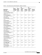
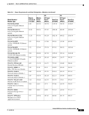
Appendix D Chassis and Module Power and Heat Values Table D-4 Power Requirements and Heat Dissipation-Modules (continued) Model Number/ Module Type Module Module Current (A) Power @ ... WS-F6K-VPWR PoE daughter card 100.38 WS-X6380-NAM 1.31 Network Analysis Module 55.02 WS-X6408A-GBIC 2.00 8-port 1000BASE-X Gigabit Ethernet module 84.00 WS-X6416-GBIC 2.81 16-port 1000BASE-X Gigabit Ethernet module 118.02 AC AC-Input Power (Watts) 165.90 Heat Diss....47 992.83 293.03 293.03 460.75 460.75 460.75 252.54 385.56 541.72 OL-5781-04 Catalyst 6500 Series Switches Installation Guide D-7
Appendix D Chassis and Module Power and Heat Values Table D-4 Power Requirements and Heat Dissipation-Modules (continued) Model Number/ Module Type Module Module Current (A) Power @ ... WS-F6K-VPWR PoE daughter card 100.38 WS-X6380-NAM 1.31 Network Analysis Module 55.02 WS-X6408A-GBIC 2.00 8-port 1000BASE-X Gigabit Ethernet module 84.00 WS-X6416-GBIC 2.81 16-port 1000BASE-X Gigabit Ethernet module 118.02 AC AC-Input Power (Watts) 165.90 Heat Diss....47 992.83 293.03 293.03 460.75 460.75 460.75 252.54 385.56 541.72 OL-5781-04 Catalyst 6500 Series Switches Installation Guide D-7
Installation Guide
Page 314
Appendix D Chassis and Module Power and Heat Values Table D-4 Power Requirements and Heat Dissipation-Modules (continued) Model Number/ Module Type Module Module Current (A) Power ... Ethernet module 105.00 WS-X6502-10GE 3.30 2-port 10-Gigabit Ethernet module 138.60 WS-X6516-GBIC 3.40 16-port 1000BASE-X Gigabit Ethernet module 142.80 WS-X6516A-GBIC 3.62 16-port 1000BASE-X Gigabit Ethernet module 152.04 WS-X6516-GE-TX 3.45 16-port 10...697.87 665.10 366.3 574.49 655.46 609.19 559.07 559.07 481.96 381.71 296.88 Catalyst 6500 Series Switches Installation Guide D-8 OL-5781-04
Appendix D Chassis and Module Power and Heat Values Table D-4 Power Requirements and Heat Dissipation-Modules (continued) Model Number/ Module Type Module Module Current (A) Power ... Ethernet module 105.00 WS-X6502-10GE 3.30 2-port 10-Gigabit Ethernet module 138.60 WS-X6516-GBIC 3.40 16-port 1000BASE-X Gigabit Ethernet module 142.80 WS-X6516A-GBIC 3.62 16-port 1000BASE-X Gigabit Ethernet module 152.04 WS-X6516-GE-TX 3.45 16-port 10...697.87 665.10 366.3 574.49 655.46 609.19 559.07 559.07 481.96 381.71 296.88 Catalyst 6500 Series Switches Installation Guide D-8 OL-5781-04
Installation Guide
Page 315
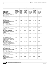
Appendix D Chassis and Module Power and Heat Values Table D-4 Power Requirements and Heat Dissipation-Modules (continued) Model Number/ Module Type WS-X6704-10GE 4-Port ...24-Port 1000BASE-X Ethernet module WS-X6748-SFP 48-Port 1000BASE-X Ethernet module WS-X6748-GE-TX 10/100/1000 Ethernet module WS-X6816-GBIC 16-Port1000BASE-X Gigabit Ethernet module WS-SVC-FWM-1-K9 Firewall Services Module WS-SVC-IPSEC-1 IPSec VPN Services Module WS-SVC-NAM-1 Network Analysis...1349.48 740.28 788.48 364.36 557.14 668.95 597.63 578.35 771.13 688.23 OL-5781-04 Catalyst 6500 Series Switches Installation Guide D-9
Appendix D Chassis and Module Power and Heat Values Table D-4 Power Requirements and Heat Dissipation-Modules (continued) Model Number/ Module Type WS-X6704-10GE 4-Port ...24-Port 1000BASE-X Ethernet module WS-X6748-SFP 48-Port 1000BASE-X Ethernet module WS-X6748-GE-TX 10/100/1000 Ethernet module WS-X6816-GBIC 16-Port1000BASE-X Gigabit Ethernet module WS-SVC-FWM-1-K9 Firewall Services Module WS-SVC-IPSEC-1 IPSec VPN Services Module WS-SVC-NAM-1 Network Analysis...1349.48 740.28 788.48 364.36 557.14 668.95 597.63 578.35 771.13 688.23 OL-5781-04 Catalyst 6500 Series Switches Installation Guide D-9
Installation Guide
Page 327
... Catalyst 6509-NEB switches 1-41 Catalyst 6509-NEB-A (figure) 2-15 Catalyst 6509-NEB-A switches 1-46 Catalyst 6513 (figure) 2-16 Catalyst 6513 switches 1-51 chassis requirements (table) 2-9 description 2-9 alarms major E-5 minor E-5 attenuators, using with 1000BASE-ZX GBIC B-5 audience, document xi B brackets See crossbar brackets, shelf brackets, stabilizer brackets branch circuit requirements 2-17 C cable guides installing on Catalyst 6506 switches 3-7 installing on Catalyst 6506-E switches 3-7 installing on Catalyst 6509 switches 3-9 installing on Catalyst 6509-E switches...
... Catalyst 6509-NEB switches 1-41 Catalyst 6509-NEB-A (figure) 2-15 Catalyst 6509-NEB-A switches 1-46 Catalyst 6513 (figure) 2-16 Catalyst 6513 switches 1-51 chassis requirements (table) 2-9 description 2-9 alarms major E-5 minor E-5 attenuators, using with 1000BASE-ZX GBIC B-5 audience, document xi B brackets See crossbar brackets, shelf brackets, stabilizer brackets branch circuit requirements 2-17 C cable guides installing on Catalyst 6506 switches 3-7 installing on Catalyst 6506-E switches 3-7 installing on Catalyst 6509 switches 3-9 installing on Catalyst 6509-E switches...
Installation Guide
Page 330
...-input power supply installing 4-16, 4-56 differential mode delay See DMD dimensions, chassis Catalyst 6503 switches 1-6 Catalyst 6503-E switches 1-10 Catalyst 6504-E switches 1-14 Catalyst 6506 switches 1-20 Catalyst 6506-E switches 1-25 Catalyst 6509 switches 1-30 Catalyst 6509-E switches 1-35 Catalyst 6509-NEB switches 1-41 Catalyst 6509-NEB-A switches 1-46 Catalyst 6513 switches 1-51 DMD correcting B-31 description B-30 IN-6 Catalyst 6500 Series Switches Installation Guide documentation audience xi conventions xii DVD xx feedback xxi obtaining additional...
...-input power supply installing 4-16, 4-56 differential mode delay See DMD dimensions, chassis Catalyst 6503 switches 1-6 Catalyst 6503-E switches 1-10 Catalyst 6504-E switches 1-14 Catalyst 6506 switches 1-20 Catalyst 6506-E switches 1-25 Catalyst 6509 switches 1-30 Catalyst 6509-E switches 1-35 Catalyst 6509-NEB switches 1-41 Catalyst 6509-NEB-A switches 1-46 Catalyst 6513 switches 1-51 DMD correcting B-31 description B-30 IN-6 Catalyst 6500 Series Switches Installation Guide documentation audience xi conventions xii DVD xx feedback xxi obtaining additional...
Installation Guide
Page 331
...tray removal warning 4-58 installing 4-65 troubleshooting E-5 fan tray removal warning 4-58 features Catalyst 6503 switches 1-2 Catalyst 6503-E switches 1-8 Catalyst 6504-E switches 1-12 Catalyst 6506 switches 1-16 Catalyst 6506-E switches 1-22 Catalyst 6509 switches 1-26 Catalyst 6509-E switches 1-32 Catalyst 6509-NEB switches 1-37 Catalyst 6509-NEB-A switches 1-43 Catalyst 6513 switches 1-48 Flash code, troubleshooting E-3 G GBICs 1000BASE-T (figure) B-6 1000BASE-X (figure) B-6 cabling specifications B-5 GBIC transceivers B-3 1000BASE-T B-3 CWDM B-10 CWDM (figure) B-13 DWDM B-11 DWDM product...
...tray removal warning 4-58 installing 4-65 troubleshooting E-5 fan tray removal warning 4-58 features Catalyst 6503 switches 1-2 Catalyst 6503-E switches 1-8 Catalyst 6504-E switches 1-12 Catalyst 6506 switches 1-16 Catalyst 6506-E switches 1-22 Catalyst 6509 switches 1-26 Catalyst 6509-E switches 1-32 Catalyst 6509-NEB switches 1-37 Catalyst 6509-NEB-A switches 1-43 Catalyst 6513 switches 1-48 Flash code, troubleshooting E-3 G GBICs 1000BASE-T (figure) B-6 1000BASE-X (figure) B-6 cabling specifications B-5 GBIC transceivers B-3 1000BASE-T B-3 CWDM B-10 CWDM (figure) B-13 DWDM B-11 DWDM product...
