
Installation Guide
Page 5
... in Cisco Products xxi Obtaining Technical Assistance xxii Cisco Technical Support Website xxii Submitting a Service Request xxii Definitions of Service Request Severity xxiii Obtaining Additional Publications and Information xxiii Product Overview 1-1 Catalyst 6503 Switch 1-2 Catalyst 6503-E Switch 1-8 Catalyst 6504-E Switch 1-13 Catalyst 6506 Switch 1-18 Catalyst 6506-E Switch 1-24 Catalyst 6509 Switch 1-28 Catalyst 6509-E Switch 1-34 Catalyst 6509-NEB Switch 1-39 Catalyst 6509-NEB-A Switch 1-45 Catalyst 6513 Switch 1-50 CONTENTS OL-5781-04 Catalyst 6500 Series Switches Installation...
... in Cisco Products xxi Obtaining Technical Assistance xxii Cisco Technical Support Website xxii Submitting a Service Request xxii Definitions of Service Request Severity xxiii Obtaining Additional Publications and Information xxiii Product Overview 1-1 Catalyst 6503 Switch 1-2 Catalyst 6503-E Switch 1-8 Catalyst 6504-E Switch 1-13 Catalyst 6506 Switch 1-18 Catalyst 6506-E Switch 1-24 Catalyst 6509 Switch 1-28 Catalyst 6509-E Switch 1-34 Catalyst 6509-NEB Switch 1-39 Catalyst 6509-NEB-A Switch 1-45 Catalyst 6513 Switch 1-50 CONTENTS OL-5781-04 Catalyst 6500 Series Switches Installation...
Installation Guide
Page 6
... Catalyst 6503-E Switches 3-8 Installing the L Brackets and Cable Guides on the Catalyst 6504-E Switch 3-10 Installing the L Brackets and Cable Guides on the Catalyst 6506 and Catalyst 6506-E Switches 3-11 Installing the L Brackets and Cable Guides on the Catalyst 6509 and Catalyst 6509-E Switches 3-13 Installing the L Brackets and Cable Guides on the Catalyst 6509-NEB Switch 3-15 Installing the L Brackets on the Catalyst 6509-NEB-A Switch 3-17 Installing the Switch Chassis...
... Catalyst 6503-E Switches 3-8 Installing the L Brackets and Cable Guides on the Catalyst 6504-E Switch 3-10 Installing the L Brackets and Cable Guides on the Catalyst 6506 and Catalyst 6506-E Switches 3-11 Installing the L Brackets and Cable Guides on the Catalyst 6509 and Catalyst 6509-E Switches 3-13 Installing the L Brackets and Cable Guides on the Catalyst 6509-NEB Switch 3-15 Installing the L Brackets on the Catalyst 6509-NEB-A Switch 3-17 Installing the Switch Chassis...
Installation Guide
Page 7
... C H A P T E R Installing the Cable Management System (Catalyst 6509-NEB-A Switch Only) 3-23 Replacing the Cable Guide 3-25 Establishing the System Ground 3-27 Required Tools and Parts 3-28 Connecting the System Ground 3-29 Installing the Power Supplies in the Switch Chassis 3-34 Attaching the Interface Cables 3-34 Connecting the Supervisor Engine Console Port ... the Fan Assembly 4-57 Installing the Fan Assembly 4-65 Checking the Installation 4-65 Installing the Air Filter Assembly on a Catalyst 6509-NEB-A Switch (Optional) 4-66 OL-5781-04 Catalyst 6500 Series Switches Installation Guide vii
... C H A P T E R Installing the Cable Management System (Catalyst 6509-NEB-A Switch Only) 3-23 Replacing the Cable Guide 3-25 Establishing the System Ground 3-27 Required Tools and Parts 3-28 Connecting the System Ground 3-29 Installing the Power Supplies in the Switch Chassis 3-34 Attaching the Interface Cables 3-34 Connecting the Supervisor Engine Console Port ... the Fan Assembly 4-57 Installing the Fan Assembly 4-65 Checking the Installation 4-65 Installing the Air Filter Assembly on a Catalyst 6509-NEB-A Switch (Optional) 4-66 OL-5781-04 Catalyst 6500 Series Switches Installation Guide vii
Installation Guide
Page 25
...: • Catalyst 6503 Switch, page 1-2 • Catalyst 6503-E Switch, page 1-8 • Catalyst 6504-E Switch, page 1-13 • Catalyst 6506 Switch, page 1-18 • Catalyst 6506-E Switch, page 1-24 • Catalyst 6509 Switch, page 1-28 • Catalyst 6509-E Switch, page 1-34 • Catalyst 6509-NEB Switch, page 1-39 • Catalyst 6509-NEB-A Switch, page 1-45 • Catalyst 6513 Switch, page 1-50 Note The Catalyst 6000 series switches (Catalyst 6006 switch and Catalyst 6009 switch) are described in a separate publication, the Catalyst 6000 Series Switches Installation...
...: • Catalyst 6503 Switch, page 1-2 • Catalyst 6503-E Switch, page 1-8 • Catalyst 6504-E Switch, page 1-13 • Catalyst 6506 Switch, page 1-18 • Catalyst 6506-E Switch, page 1-24 • Catalyst 6509 Switch, page 1-28 • Catalyst 6509-E Switch, page 1-34 • Catalyst 6509-NEB Switch, page 1-39 • Catalyst 6509-NEB-A Switch, page 1-45 • Catalyst 6513 Switch, page 1-50 Note The Catalyst 6000 series switches (Catalyst 6006 switch and Catalyst 6009 switch) are described in a separate publication, the Catalyst 6000 Series Switches Installation...
Installation Guide
Page 28
...chassis that are installed in the lower power supply bay. Source AC can be of phase between multiple power supplies or multiple AC-power plugs on the same power supply because all AC power supply inputs are isolated. • Single power supplies are equipped with DC-input power supplies, the system (NEBS...required for these chassis do not have a separate ground. • All Catalyst 6500 series AC-input power supplies require single-phase source AC. PEM-DC/3 (PEM for 1400 W AC-input power supplies). • Supports one DC-input. Catalyst 6500 Series Switches Installation Guide 1-4...
...chassis that are installed in the lower power supply bay. Source AC can be of phase between multiple power supplies or multiple AC-power plugs on the same power supply because all AC power supply inputs are isolated. • Single power supplies are equipped with DC-input power supplies, the system (NEBS...required for these chassis do not have a separate ground. • All Catalyst 6500 series AC-input power supplies require single-phase source AC. PEM-DC/3 (PEM for 1400 W AC-input power supplies). • Supports one DC-input. Catalyst 6500 Series Switches Installation Guide 1-4...

Installation Guide
Page 29
... with internal air temperature sensors that are equipped with Network Equipment Building Systems (NEBS) (Zone 4 per axis (1.12 Grms). 64 to 76 dB. Chapter 1 Product Overview Catalyst 6503 Switch Table 1-2 Catalyst 6503 Switch Specifications Item Environmental Temperature, operating Specification Certified for operation: 32° to ...176; to 40°C) Designed and tested for operation: 32° to 130°F (0° to 55°C) Note The Catalyst 6500 series switches are triggered at 40°C (104°F) generating a minor alarm and at each end. 0.5 hours per GR-63-Core) ...
... with internal air temperature sensors that are equipped with Network Equipment Building Systems (NEBS) (Zone 4 per axis (1.12 Grms). 64 to 76 dB. Chapter 1 Product Overview Catalyst 6503 Switch Table 1-2 Catalyst 6503 Switch Specifications Item Environmental Temperature, operating Specification Certified for operation: 32° to ...176; to 40°C) Designed and tested for operation: 32° to 130°F (0° to 55°C) Note The Catalyst 6500 series switches are triggered at 40°C (104°F) generating a minor alarm and at each end. 0.5 hours per GR-63-Core) ...

Installation Guide
Page 34
...NEBS) (Zone 4 per axis (1.12 Grms). 64 to 76 dB. International Organization for Standardization (ISO) 7779: Bystander position operating to an ambient temperature of 86°F (30°C). 1-10 Catalyst 6500 Series Switches Installation Guide OL-5781-04 Catalyst 6503-E Switch Chapter 1 Product Overview Table 1-4 Catalyst 6503-E Switch...176; to 40°C) Designed and tested for operation: 32° to 130°F (0° to 55°C) Note The Catalyst 6500 series switches are triggered at 40°C (104°F) generating a minor alarm and at each end. 0.5 hours per GR-63-Core) in...
...NEBS) (Zone 4 per axis (1.12 Grms). 64 to 76 dB. International Organization for Standardization (ISO) 7779: Bystander position operating to an ambient temperature of 86°F (30°C). 1-10 Catalyst 6500 Series Switches Installation Guide OL-5781-04 Catalyst 6503-E Switch Chapter 1 Product Overview Table 1-4 Catalyst 6503-E Switch...176; to 40°C) Designed and tested for operation: 32° to 130°F (0° to 55°C) Note The Catalyst 6500 series switches are triggered at 40°C (104°F) generating a minor alarm and at each end. 0.5 hours per GR-63-Core) in...
Installation Guide
Page 39
...of 86°F (30°C). • 8.7 x 17.5 x 21.6 in. (22.09 x 44.45 x 54.86 cm). • Chassis requires 5 RU1. • The Catalyst 6504-E switch chassis is designed to install in standard 19-inch equipment racks that meet ANSI/EIA 310-D, IEC 60297, and ETS 300-119 standards. •...; Chassis only: 27 lb (12.25 kg). • Chassis fully configured with Network Equipment Building Systems (NEBS) (Zone 4 per GR-63...
...of 86°F (30°C). • 8.7 x 17.5 x 21.6 in. (22.09 x 44.45 x 54.86 cm). • Chassis requires 5 RU1. • The Catalyst 6504-E switch chassis is designed to install in standard 19-inch equipment racks that meet ANSI/EIA 310-D, IEC 60297, and ETS 300-119 standards. •...; Chassis only: 27 lb (12.25 kg). • Chassis fully configured with Network Equipment Building Systems (NEBS) (Zone 4 per GR-63...

Installation Guide
Page 45
... major alarm. OL-5781-04 Catalyst 6500 Series Switches Installation Guide 1-21 Chapter 1 Product Overview Catalyst 6506 Switch Table 1-8 Catalyst 6506 Switch Specifications Item Environmental Temperature, operating... Specification Certified for operation: 32° to 104°F (0° to 40°C) Designed and tested for operation: -200 to 10,000 feet (-60 to 3000 m) This switch complies with internal air temperature sensors that are equipped with Network Equipment Building Systems (NEBS...
... major alarm. OL-5781-04 Catalyst 6500 Series Switches Installation Guide 1-21 Chapter 1 Product Overview Catalyst 6506 Switch Table 1-8 Catalyst 6506 Switch Specifications Item Environmental Temperature, operating... Specification Certified for operation: 32° to 104°F (0° to 40°C) Designed and tested for operation: -200 to 10,000 feet (-60 to 3000 m) This switch complies with internal air temperature sensors that are equipped with Network Equipment Building Systems (NEBS...

Installation Guide
Page 50
... with internal air temperature sensors that are equipped with Network Equipment Building Systems (NEBS) (Zone 4 per axis (1.12 Grms). 53 to an ambient temperature of 86°F (30°C). 1-26 Catalyst 6500 Series Switches Installation Guide OL-5781-04 Temperature, nonoperating and storage Thermal transition Humidity (RH), ambient (noncondensing) operating Humidity (RH), ambient...
... with internal air temperature sensors that are equipped with Network Equipment Building Systems (NEBS) (Zone 4 per axis (1.12 Grms). 53 to an ambient temperature of 86°F (30°C). 1-26 Catalyst 6500 Series Switches Installation Guide OL-5781-04 Temperature, nonoperating and storage Thermal transition Humidity (RH), ambient (noncondensing) operating Humidity (RH), ambient...

Installation Guide
Page 55
...; to 130°F (0° to 55°C) Note The Catalyst 6500 series switches are equipped with Network Equipment Building Systems (NEBS) (Zone 4 per axis (1.12 Grms). 53.6 to 68 dB. OL-5781-04 Catalyst 6500 Series Switches Installation Guide 1-31 Chapter 1 Product Overview Catalyst 6509 Switch Table 1-12 Catalyst 6509 Switch Specifications Item Environmental Temperature, operating Specification Certified for operation: 32...
...; to 130°F (0° to 55°C) Note The Catalyst 6500 series switches are equipped with Network Equipment Building Systems (NEBS) (Zone 4 per axis (1.12 Grms). 53.6 to 68 dB. OL-5781-04 Catalyst 6500 Series Switches Installation Guide 1-31 Chapter 1 Product Overview Catalyst 6509 Switch Table 1-12 Catalyst 6509 Switch Specifications Item Environmental Temperature, operating Specification Certified for operation: 32...

Installation Guide
Page 60
Catalyst 6509-E Switch Chapter 1 Product Overview Table 1-14 Catalyst 6509-E Switch Specifications Item Environmental Temperature, operating Specification Certified for operation: 32° to 104°F (0° to 40°C) Designed and tested for operation: 32° to 130°F (0° to 55°C) Note The Catalyst 6500 series switches...temperature of 86°F (30°C). 1-36 Catalyst 6500 Series Switches Installation Guide OL-5781-04 Temperature, nonoperating and...switch complies with internal air temperature sensors that are equipped with Network Equipment Building ...
Catalyst 6509-E Switch Chapter 1 Product Overview Table 1-14 Catalyst 6509-E Switch Specifications Item Environmental Temperature, operating Specification Certified for operation: 32° to 104°F (0° to 40°C) Designed and tested for operation: 32° to 130°F (0° to 55°C) Note The Catalyst 6500 series switches...temperature of 86°F (30°C). 1-36 Catalyst 6500 Series Switches Installation Guide OL-5781-04 Temperature, nonoperating and...switch complies with internal air temperature sensors that are equipped with Network Equipment Building ...

Installation Guide
Page 63
... the specifications of the Catalyst 6509-NEB switch chassis. Require that you install a Supervisor Engine 720 - Supervisor Engine 720 has built-in slot 5 or slot 6. • Some Catalyst 6500 series modules may: - Supervisor Engine 1 and Supervisor Engine 2 are in slot 1 or slot 2. - Chapter 1 Product Overview Catalyst 6509-NEB Switch Catalyst 6509-NEB Switch The Catalyst 6509-NEB switch is installed in slot 5 or slot 6. - Switch Fabric Modules are numbered...
... the specifications of the Catalyst 6509-NEB switch chassis. Require that you install a Supervisor Engine 720 - Supervisor Engine 720 has built-in slot 5 or slot 6. • Some Catalyst 6500 series modules may: - Supervisor Engine 1 and Supervisor Engine 2 are in slot 1 or slot 2. - Chapter 1 Product Overview Catalyst 6509-NEB Switch Catalyst 6509-NEB Switch The Catalyst 6509-NEB switch is installed in slot 5 or slot 6. - Switch Fabric Modules are numbered...

Installation Guide
Page 64
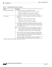
... from this front panel DC power connector through a power harness also provided in the Catalyst 6509-NEB switch. Note Both fan tray models contain nine individual fans. WS-C6509-NEB-FAN (Standard fan tray-294 CFM). does not support Supervisor Engine 32 or Supervisor Engine...tray from an AC source, you are operating the chassis from the site source DC. The individual fans are supported: - These fan tray models are not field replaceable. Catalyst 6509-NEB Switch Chapter 1 Product Overview Table 1-15 Catalyst 6509-NEB Switch Features (continued) Feature Fan Tray Features • ...
... from this front panel DC power connector through a power harness also provided in the Catalyst 6509-NEB switch. Note Both fan tray models contain nine individual fans. WS-C6509-NEB-FAN (Standard fan tray-294 CFM). does not support Supervisor Engine 32 or Supervisor Engine...tray from an AC source, you are operating the chassis from the site source DC. The individual fans are supported: - These fan tray models are not field replaceable. Catalyst 6509-NEB Switch Chapter 1 Product Overview Table 1-15 Catalyst 6509-NEB Switch Features (continued) Feature Fan Tray Features • ...
Installation Guide
Page 65
... configured in either redundant or non-redundant mode. • All Catalyst 6500 series AC-input power supplies require single-phase source AC. OL-5781-04 Catalyst 6500 Series Switches Installation Guide 1-41 WS-CAC-4000W-INT (4000 W AC-input... of different wattage ratings. Refer to the Catalyst 6509-NEB Switch and Cisco OSR-7609 Router Upgrade Note for kit installation instructions. WS-CDC-2500W (2500 W DC-input power supply). - Chapter 1 Product Overview Catalyst 6509-NEB Switch Table 1-15 Catalyst 6509-NEB Switch Features (continued) Feature Features Power Supply &#...
... configured in either redundant or non-redundant mode. • All Catalyst 6500 series AC-input power supplies require single-phase source AC. OL-5781-04 Catalyst 6500 Series Switches Installation Guide 1-41 WS-CAC-4000W-INT (4000 W AC-input... of different wattage ratings. Refer to the Catalyst 6509-NEB Switch and Cisco OSR-7609 Router Upgrade Note for kit installation instructions. WS-CDC-2500W (2500 W DC-input power supply). - Chapter 1 Product Overview Catalyst 6509-NEB Switch Table 1-15 Catalyst 6509-NEB Switch Features (continued) Feature Features Power Supply &#...

Installation Guide
Page 66
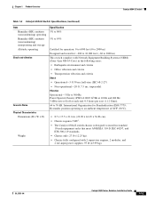
... triggered at 40°C (104°F) generating a minor alarm and at each end. 0.5 hours per axis (1.12 Grms). 56.4 to 75 dB. Catalyst 6509-NEB Switch Chapter 1 Product Overview Table 1-16 Catalyst 6509-NEB Switch Specifications Item Environmental Temperature, operating Specification Certified for operation: 32° to 104°F (0° to 40°C) Designed and tested for operation...
... triggered at 40°C (104°F) generating a minor alarm and at each end. 0.5 hours per axis (1.12 Grms). 56.4 to 75 dB. Catalyst 6509-NEB Switch Chapter 1 Product Overview Table 1-16 Catalyst 6509-NEB Switch Specifications Item Environmental Temperature, operating Specification Certified for operation: 32° to 104°F (0° to 40°C) Designed and tested for operation...
Installation Guide
Page 67
...-5781-04 Catalyst 6500 Series Switches Installation Guide 1-43 You should also allow a minimum separation of the WS-6509-NEB-UPGRD kit. Failure to maintain adequate air space can cause the chassis to overheat and the system to back, the chassis may be placed side-by-side. 1. Chassis only: 55 lb (24.9 kg). On Catalyst chassis in standard 19...
...-5781-04 Catalyst 6500 Series Switches Installation Guide 1-43 You should also allow a minimum separation of the WS-6509-NEB-UPGRD kit. Failure to maintain adequate air space can cause the chassis to overheat and the system to back, the chassis may be placed side-by-side. 1. Chassis only: 55 lb (24.9 kg). On Catalyst chassis in standard 19...

Installation Guide
Page 68
... 5 LINK 5 LINK 5 LINK 6 LINK 6 LINK 6 LINK 7 LINK 7 LINK 7 LINK PORT 2 LINK PORT 2 LINK 8 LINK 8 LINK 8 LINK FAN OUTPUT OK FAIL o o Catalyst 6500 Series Switches Installation Guide Power supply 1 INPUT OK Catalyst 6509-NEB Switch Figure 1-11 Catalyst 6509-NEB Switch Switching modules FAN STATUS Fan assembly WS-X6224 1 2 3 4 5 6 7 8 9 10 11 12 13 14 15 16 17 18 19 20 21 22...
... 5 LINK 5 LINK 5 LINK 6 LINK 6 LINK 6 LINK 7 LINK 7 LINK 7 LINK PORT 2 LINK PORT 2 LINK 8 LINK 8 LINK 8 LINK FAN OUTPUT OK FAIL o o Catalyst 6500 Series Switches Installation Guide Power supply 1 INPUT OK Catalyst 6509-NEB Switch Figure 1-11 Catalyst 6509-NEB Switch Switching modules FAN STATUS Fan assembly WS-X6224 1 2 3 4 5 6 7 8 9 10 11 12 13 14 15 16 17 18 19 20 21 22...

Installation Guide
Page 69
Chapter 1 Product Overview Catalyst 6509-NEB-A Switch Catalyst 6509-NEB-A Switch Table 1-17 lists the features of the Catalyst 6509-NEB-A switch chassis. Table 1-17 Catalyst 6509-NEB-A Switch Features Feature Chassis Supervisor Engines Description • Nine vertical slots. Figure 1-12 shows the Catalyst 6509-NEB-A switch chassis. Require that you install a Supervisor Engine 720 - OL-5781-04 Catalyst 6500 Series Switches Installation Guide 1-45 Modules Backplane Bandwidth Clock and VTT Modules Note Redundant supervisor engines...
Chapter 1 Product Overview Catalyst 6509-NEB-A Switch Catalyst 6509-NEB-A Switch Table 1-17 lists the features of the Catalyst 6509-NEB-A switch chassis. Table 1-17 Catalyst 6509-NEB-A Switch Features Feature Chassis Supervisor Engines Description • Nine vertical slots. Figure 1-12 shows the Catalyst 6509-NEB-A switch chassis. Require that you install a Supervisor Engine 720 - OL-5781-04 Catalyst 6500 Series Switches Installation Guide 1-45 Modules Backplane Bandwidth Clock and VTT Modules Note Redundant supervisor engines...

Installation Guide
Page 70
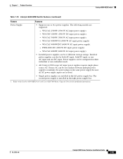
... phase between multiple power supplies or multiple AC-power plugs on the same power supply because all AC power supply inputs are supported: - Catalyst 6509-NEB-A Switch Chapter 1 Product Overview Table 1-17 Catalyst 6509-NEB-A Switch Features (continued) Feature Fan Tray Description • Supports two hot-swappable fan trays. The individual fans are supported: - WS-CAC-4000W-US...
... phase between multiple power supplies or multiple AC-power plugs on the same power supply because all AC power supply inputs are supported: - Catalyst 6509-NEB-A Switch Chapter 1 Product Overview Table 1-17 Catalyst 6509-NEB-A Switch Features (continued) Feature Fan Tray Description • Supports two hot-swappable fan trays. The individual fans are supported: - WS-CAC-4000W-US...