
Service Manual
Page 267
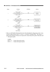
...not the copier's. The symbol "+" indicates the terminal to which you will find the following instructions when checking the voltage using a meter: "measure the voltage between J109-1 (+) and -2 (-) on the DC controller PCB." Connect the negative probe. 11-2 COPYRIGHT © 1999 CANON INC. ...at the NO Advise the user that the problem power source? CANON PC800s/900s REV.0 AUG. 1999 PRINTED IN JAPAN (IMPRIME AU JAPON) Connect the positive probe. example: J109-1 (+) ..... CHAPTER 11 TROUBLESHOOTING Is the power 1 plug connected to connect the positive probe...
...not the copier's. The symbol "+" indicates the terminal to which you will find the following instructions when checking the voltage using a meter: "measure the voltage between J109-1 (+) and -2 (-) on the DC controller PCB." Connect the negative probe. 11-2 COPYRIGHT © 1999 CANON INC. ...at the NO Advise the user that the problem power source? CANON PC800s/900s REV.0 AUG. 1999 PRINTED IN JAPAN (IMPRIME AU JAPON) Connect the positive probe. example: J109-1 (+) ..... CHAPTER 11 TROUBLESHOOTING Is the power 1 plug connected to connect the positive probe...

Service Manual
Page 270
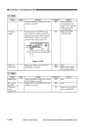
Copier a. Caution: If you have performed this adjustment, be sure to adjust the image leading edge margin. 2.0 ± 1.5mm Figure 11-201 1) Turn VR105 on the ... VR105 and Leading Edge Non-Image Width Direction of VR105 Clockwise Counterclockwise Leading edge non-image width Decreases Increases Table 11-201 COPYRIGHT © 1999 CANON INC. CANON PC800s/900s REV.0 AUG. 1999 PRINTED IN JAPAN (IMPRIME AU JAPON) 11-5 STANDARDS AND ADJUSTMENTS A. CHAPTER 11 TROUBLESHOOTING II.
Copier a. Caution: If you have performed this adjustment, be sure to adjust the image leading edge margin. 2.0 ± 1.5mm Figure 11-201 1) Turn VR105 on the ... VR105 and Leading Edge Non-Image Width Direction of VR105 Clockwise Counterclockwise Leading edge non-image width Decreases Increases Table 11-201 COPYRIGHT © 1999 CANON INC. CANON PC800s/900s REV.0 AUG. 1999 PRINTED IN JAPAN (IMPRIME AU JAPON) 11-5 STANDARDS AND ADJUSTMENTS A. CHAPTER 11 TROUBLESHOOTING II.
Service Manual
Page 331
... End. NO Replace the composite power supply PCB. 11-66 11-66 COPYRIGHT © 1999 CANON INC. NO Replace the copier's DC controller PCB. 13 E803 Cause Malfunction DC controller PCB. Is the problem corrected? CHAPTER 11 TROUBLESHOOTING 12 E400 Cause Step 1 Checks Turn off and then on the power switch. YES End...
... End. NO Replace the composite power supply PCB. 11-66 11-66 COPYRIGHT © 1999 CANON INC. NO Replace the copier's DC controller PCB. 13 E803 Cause Malfunction DC controller PCB. Is the problem corrected? CHAPTER 11 TROUBLESHOOTING 12 E400 Cause Step 1 Checks Turn off and then on the power switch. YES End...
Service Manual
Page 352
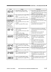
...• The actual output value of the power supply is faulty. • The composite power supply PCB is faulty. • Data communication between the copier and the ADF (faulty). • The DC controller PCB is faulty. • The composite power supply PCB is faulty. • The lens hoe ... panel are locked • The scanner/lens drive motor (M2) is faulty. • The DC controller PCB is faulty. COPYRIGHT © 1999 CANON INC. CHAPTER 11 TROUBLESHOOTING Code Cause • The main motor (M1) is fault. • The DC controller PCB is faulty. • The composite power supply PCB...
...• The actual output value of the power supply is faulty. • The composite power supply PCB is faulty. • Data communication between the copier and the ADF (faulty). • The DC controller PCB is faulty. • The composite power supply PCB is faulty. • The lens hoe ... panel are locked • The scanner/lens drive motor (M2) is faulty. • The DC controller PCB is faulty. COPYRIGHT © 1999 CANON INC. CHAPTER 11 TROUBLESHOOTING Code Cause • The main motor (M1) is fault. • The DC controller PCB is faulty. • The composite power supply PCB...


