
Service Manual
Page 7
... A. Outline of Operations 2-3 D. Control Panel 1-15 V. Inputs to and Outputs from the DC Controller 2-7 CHAPTER 3 EXPOSURE SYSTEM I . DISASSEMBLY/ASSEMBLY ..... 3-12 A. CANON PC800s/900s REV.0 AUG. 1999 PRINTED IN JAPAN (IMPRIME AU JAPON) v Copier 1-2 B. NAMES OF PARTS 1-10 ...A. Varying the Reproduction Ratio 3-2 C. Scanner Drive Assembly .... 3-13 B. BASIC OPERATIONS 2-1 A. Controlling the Main Motor (M1 2-5 E. Controlling the Scanning Lamp 3-9 ...
... A. Outline of Operations 2-3 D. Control Panel 1-15 V. Inputs to and Outputs from the DC Controller 2-7 CHAPTER 3 EXPOSURE SYSTEM I . DISASSEMBLY/ASSEMBLY ..... 3-12 A. CANON PC800s/900s REV.0 AUG. 1999 PRINTED IN JAPAN (IMPRIME AU JAPON) v Copier 1-2 B. NAMES OF PARTS 1-10 ...A. Varying the Reproduction Ratio 3-2 C. Scanner Drive Assembly .... 3-13 B. BASIC OPERATIONS 2-1 A. Controlling the Main Motor (M1 2-5 E. Controlling the Scanning Lamp 3-9 ...
Service Manual
Page 10
...A-27 H. Points to Note for Servicing 11-4 II. TROUBLESHOOTING FEEDING PROBLEMS 11-75 A. ARRANGEMENT AND FUNCTIONS OF ELECTRICAL PARTS 11-79 A. Lamp, Heater, Motor, Etc. 11-81 D. ADF 11-83 F. SELF DIAGNOSIS 11-86 APPENDIX A. GENERAL CIRCUIT DIAGRAM A-5 D. AE SENSOR .... CANON PC800s/900s REV.0 AUG. 1999 PRINTED IN JAPAN (IMPRIME AU JAPON) Electrical 11-41 III. Sample Image Faults ....... 11-52 C. SIGNALS AND ABBREVIATIONS A-3 C. BLANK EXPOSURE (front) CIRCUIT DIAGRAM A-33 M. NOISE FILTER CIRCUIT DIAGRAM A-31 K. COMPOSITE POWER SUPPLY CIRCUIT DIAGRAM...
...A-27 H. Points to Note for Servicing 11-4 II. TROUBLESHOOTING FEEDING PROBLEMS 11-75 A. ARRANGEMENT AND FUNCTIONS OF ELECTRICAL PARTS 11-79 A. Lamp, Heater, Motor, Etc. 11-81 D. ADF 11-83 F. SELF DIAGNOSIS 11-86 APPENDIX A. GENERAL CIRCUIT DIAGRAM A-5 D. AE SENSOR .... CANON PC800s/900s REV.0 AUG. 1999 PRINTED IN JAPAN (IMPRIME AU JAPON) Electrical 11-41 III. Sample Image Faults ....... 11-52 C. SIGNALS AND ABBREVIATIONS A-3 C. BLANK EXPOSURE (front) CIRCUIT DIAGRAM A-33 M. NOISE FILTER CIRCUIT DIAGRAM A-31 K. COMPOSITE POWER SUPPLY CIRCUIT DIAGRAM...
Service Manual
Page 14
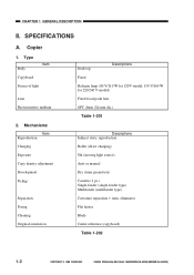
...CHAPTER 1 GENERAL DESCRIPTION II. CANON PC800s/900s REV.0 AUG. 1999 PRINTED IN JAPAN (IMPRIME AU JAPON) Type Item Body Copyboard Source of light Lens Photosensitive medium 2. Mechanisms Item Reproduction Charging Exposure Copy density adjustment Development Pickup Separation Fixing Cleaning Original orientation Desk top Descriptions Fixed Halogen lamp (80 V/110 W for... (single-feeder type) Multifeeder (multifeeder type) Curvature separation + static eliminator Flat heater Blade Center reference (copyboard) Table 1-202 1-2 COPYRIGHT © 1999 CANON INC. SPECIFICATIONS A.
...CHAPTER 1 GENERAL DESCRIPTION II. CANON PC800s/900s REV.0 AUG. 1999 PRINTED IN JAPAN (IMPRIME AU JAPON) Type Item Body Copyboard Source of light Lens Photosensitive medium 2. Mechanisms Item Reproduction Charging Exposure Copy density adjustment Development Pickup Separation Fixing Cleaning Original orientation Desk top Descriptions Fixed Halogen lamp (80 V/110 W for... (single-feeder type) Multifeeder (multifeeder type) Curvature separation + static eliminator Flat heater Blade Center reference (copyboard) Table 1-202 1-2 COPYRIGHT © 1999 CANON INC. SPECIFICATIONS A.
Service Manual
Page 49
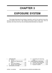
... Lamp 3-9 III. Lens Drive Assembly ......... 3-31 C. Exposure System 3-37 COPYRIGHT © 1999 CANON INC. It also explains the timing at which these drive units are operated, and shows how they may be disassembled/assmbled and adjusted. Lens Drive System 3-3 D. EXPOSURE SYSTEM 3-9 A. CANON PC800s.../900s REV.0 AUG. 1999 PRINTED IN JAPAN (IMPRIME AU JAPON) CHAPTER 3 EXPOSURE SYSTEM This chapter discusses the principles of operation used for the machine's lens...
... Lamp 3-9 III. Lens Drive Assembly ......... 3-31 C. Exposure System 3-37 COPYRIGHT © 1999 CANON INC. It also explains the timing at which these drive units are operated, and shows how they may be disassembled/assmbled and adjusted. Lens Drive System 3-3 D. EXPOSURE SYSTEM 3-9 A. CANON PC800s.../900s REV.0 AUG. 1999 PRINTED IN JAPAN (IMPRIME AU JAPON) CHAPTER 3 EXPOSURE SYSTEM This chapter discusses the principles of operation used for the machine's lens...
Service Manual
Page 51
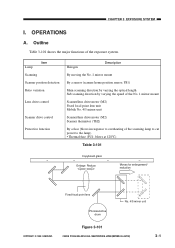
OPERATIONS A. Outline Table 3-101 shows the major functions of the scanning lamp to cut power to overheating of the exposure system. Figure 3-101 CANON PC800s/900s REV.0 AUG. 1999 PRINTED IN JAPAN (IMPRIME AU JAPON) 3-1 CHAPTER 3 EXPOSURE SYSTEM I. blows at 128°C) Table 3-101 Copyboard glass Enlarge Reduce Moves for enlargement/ reduction Fixed focal point...
OPERATIONS A. Outline Table 3-101 shows the major functions of the scanning lamp to cut power to overheating of the exposure system. Figure 3-101 CANON PC800s/900s REV.0 AUG. 1999 PRINTED IN JAPAN (IMPRIME AU JAPON) 3-1 CHAPTER 3 EXPOSURE SYSTEM I. blows at 128°C) Table 3-101 Copyboard glass Enlarge Reduce Moves for enlargement/ reduction Fixed focal point...
Service Manual
Page 53
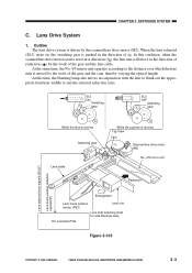
CANON PC800s/900s REV.0 AUG. 1999 PRINTED IN JAPAN (IMPRIME AU JAPON) 3-3 In this time, the blanking lamp also moves in conjunction with the lens to blank out the appropriate front/rear widths to the distance over which the lens unit is driven ... motor (M2) No. 4/5 mirror unit Reduction Enlargement Lens home position sensor (PS2) Lens unit Lens shift detecting shaft for side blanking lamp DC controller PCB Figure 3-103 COPYRIGHT © 1999 CANON INC. When the lens solenoid (SL3) turns on, the switching gear is moving Switching gear SL3 Lens cable While the scanner...
CANON PC800s/900s REV.0 AUG. 1999 PRINTED IN JAPAN (IMPRIME AU JAPON) 3-3 In this time, the blanking lamp also moves in conjunction with the lens to blank out the appropriate front/rear widths to the distance over which the lens unit is driven ... motor (M2) No. 4/5 mirror unit Reduction Enlargement Lens home position sensor (PS2) Lens unit Lens shift detecting shaft for side blanking lamp DC controller PCB Figure 3-103 COPYRIGHT © 1999 CANON INC. When the lens solenoid (SL3) turns on, the switching gear is moving Switching gear SL3 Lens cable While the scanner...
Service Manual
Page 55
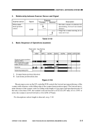
...) 3-5 Basic Sequence of the scanner home position signal. COPYRIGHT © 1999 CANON INC. The forward movement distance of the scanner varies according to the falling edge... home position sensor (PS1) Pre-registration roller paper sensor (Q751) Scanner I II I Scanning lamp(LA1) Forward Reverse I : Scanner home position detection II : Lens home position detection Figure ...the scanner with reference to the length of reference for A4 (297 mm); CHAPTER 3 EXPOSURE SYSTEM 2. Relationship between Scanner Sensor and Signal Scanner sensor PS1(scanner home position sensor) ...
...) 3-5 Basic Sequence of the scanner home position signal. COPYRIGHT © 1999 CANON INC. The forward movement distance of the scanner varies according to the falling edge... home position sensor (PS1) Pre-registration roller paper sensor (Q751) Scanner I II I Scanning lamp(LA1) Forward Reverse I : Scanner home position detection II : Lens home position detection Figure ...the scanner with reference to the length of reference for A4 (297 mm); CHAPTER 3 EXPOSURE SYSTEM 2. Relationship between Scanner Sensor and Signal Scanner sensor PS1(scanner home position sensor) ...
Service Manual
Page 56
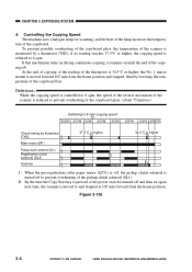
...the No. 1 mirror mount is reduced to prevent overheating of the pickup clutch solenoid (SL1). Figure 3-106 3-6 COPYRIGHT © 1999 CANON INC. if its reading reaches 37.5°C or higher, the copying speed is moved forward 105 mm from the home position. Reference: While... stopped, thereby lowering the temperature of the copyboard. CANON PC800s/900s REV.0 AUG. 1999 PRINTED IN JAPAN (IMPRIME AU JAPON) CHAPTER 3 EXPOSURE SYSTEM 4. To prevent possible overheating of the copyboard glass, the temperature of the lamp increases the tempera- If this mechanism turns on during...
...the No. 1 mirror mount is reduced to prevent overheating of the pickup clutch solenoid (SL1). Figure 3-106 3-6 COPYRIGHT © 1999 CANON INC. if its reading reaches 37.5°C or higher, the copying speed is moved forward 105 mm from the home position. Reference: While... stopped, thereby lowering the temperature of the copyboard. CANON PC800s/900s REV.0 AUG. 1999 PRINTED IN JAPAN (IMPRIME AU JAPON) CHAPTER 3 EXPOSURE SYSTEM 4. To prevent possible overheating of the copyboard glass, the temperature of the lamp increases the tempera- If this mechanism turns on during...
Service Manual
Page 59
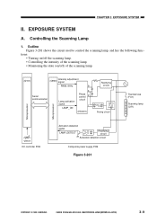
... circuit 7 Rectifying circuit (HIC001) Arcing circuit Thermal fuse (FU1) Scanning lamp (LA1) Microprocessor Microprocessor VR107 DC controller PCB Activation detection signal LAMP_DETECT Rectifying circuit Activation detection circuit Composite power supply PCB Figure 3-201 COPYRIGHT © 1999 CANON INC. CHAPTER 3 EXPOSURE SYSTEM II. CANON PC800s/900s REV.0 AUG. 1999 PRINTED IN JAPAN (IMPRIME AU JAPON...
... circuit 7 Rectifying circuit (HIC001) Arcing circuit Thermal fuse (FU1) Scanning lamp (LA1) Microprocessor Microprocessor VR107 DC controller PCB Activation detection signal LAMP_DETECT Rectifying circuit Activation detection circuit Composite power supply PCB Figure 3-201 COPYRIGHT © 1999 CANON INC. CHAPTER 3 EXPOSURE SYSTEM II. CANON PC800s/900s REV.0 AUG. 1999 PRINTED IN JAPAN (IMPRIME AU JAPON...
Service Manual
Page 60
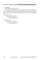
...controls the intensity adjustment signal (PWM_1KHz) and the lamp activation signal (LAMP_ON) to control the scanning lamp. When LAMP_ON is '0', The phase control circuit turns on . CANON PC800s/900s REV.0 AUG. 1999 PRINTED IN ...JAPAN (IMPRIME AU JAPON) The arcing circuit turns on /off . The scanning lamp turns off . Operations a. When LAMP_ON is '1', The phase control circuit turns off . 3-10 COPYRIGHT © 1999 CANON INC. The arcing circuit turns off the scanning lamp (LA1). The scanning lamp turns on . CHAPTER 3 EXPOSURE...
...controls the intensity adjustment signal (PWM_1KHz) and the lamp activation signal (LAMP_ON) to control the scanning lamp. When LAMP_ON is '0', The phase control circuit turns on . CANON PC800s/900s REV.0 AUG. 1999 PRINTED IN ...JAPAN (IMPRIME AU JAPON) The arcing circuit turns on /off . The scanning lamp turns off . Operations a. When LAMP_ON is '1', The phase control circuit turns off . 3-10 COPYRIGHT © 1999 CANON INC. The arcing circuit turns off the scanning lamp (LA1). The scanning lamp turns on . CHAPTER 3 EXPOSURE...
Service Manual
Page 61
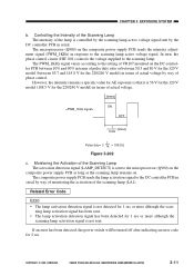
...detection signal (LAMP_DETECT) is 56 V for the 120 V model (108.5 V for 2 sec. The PWM_1KHz signal varies according to the scanning lamp active voltage signal. CANON PC800s/900s REV.0 AUG. 1999 PRINTED IN JAPAN (IMPRIME AU JAPON) 3-11 The microprocessor (Q900) on the DC controller PCB between 85.7 ...more although the scan- ment signal (PWM_1KHz) in terms of actual voltage by way of monitoring the activation of the scanning lamp (LA1). Monitoring the Activation of actual voltage. However, the intensity remains a specific value for AE exposure so that it is sent to the scanning...
...detection signal (LAMP_DETECT) is 56 V for the 120 V model (108.5 V for 2 sec. The PWM_1KHz signal varies according to the scanning lamp active voltage signal. CANON PC800s/900s REV.0 AUG. 1999 PRINTED IN JAPAN (IMPRIME AU JAPON) 3-11 The microprocessor (Q900) on the DC controller PCB between 85.7 ...more although the scan- ment signal (PWM_1KHz) in terms of actual voltage by way of monitoring the activation of the scanning lamp (LA1). Monitoring the Activation of actual voltage. However, the intensity remains a specific value for AE exposure so that it is sent to the scanning...
Service Manual
Page 74
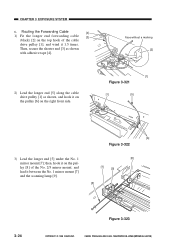
...1 mirror mount [7]; Face without a marking [2] 2) Lead the longer end [5] along the cable drive pulley [1] as shown with adhesive tape [4]. CANON PC800s/900s REV.0 AUG. 1999 PRINTED IN JAPAN (IMPRIME AU JAPON) Then, secure the shorter end [3] as shown, and hook it on the...on the pulley [8] of the cable drive pulley [1], and wind it between the No. 1 mirror mount [7] and the scanning lamp [9]. [8] [7] [9] [5] 3-24 Figure 3-323 COPYRIGHT © 1999 CANON INC. Routing the Forwarding Cable [4] 1) Fit the longer end forwarding cable [3] (black) [2] on the top hook of ...
...1 mirror mount [7]; Face without a marking [2] 2) Lead the longer end [5] along the cable drive pulley [1] as shown with adhesive tape [4]. CANON PC800s/900s REV.0 AUG. 1999 PRINTED IN JAPAN (IMPRIME AU JAPON) Then, secure the shorter end [3] as shown, and hook it on the...on the pulley [8] of the cable drive pulley [1], and wind it between the No. 1 mirror mount [7] and the scanning lamp [9]. [8] [7] [9] [5] 3-24 Figure 3-323 COPYRIGHT © 1999 CANON INC. Routing the Forwarding Cable [4] 1) Fit the longer end forwarding cable [3] (black) [2] on the top hook of ...
Service Manual
Page 75
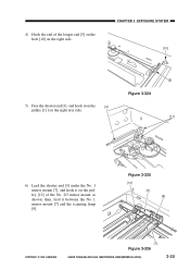
Figure 3-325 [12] [3] [9] COPYRIGHT © 1999 CANON INC. [7] Figure 3-326 CANON PC800s/900s REV.0 AUG. 1999 PRINTED IN JAPAN (IMPRIME AU JAPON) 3-25 CHAPTER 3 EXPOSURE SYSTEM [10] 5) Free the shorter end [3], and hook it on the [3] pulley [11] on the right side. 4) Hook the end of the No. 2/3 mirror mount as shown; then, lead it on the pulley [12] of the longer end [5] on the hole [10] on the right rear side. [5] Figure 3-324 [11] 6) Lead the shorter end [3] under the No. 1 mirror mount [7], and hook it between the No. 1 mirror mount [7] and the scanning lamp [9].
Figure 3-325 [12] [3] [9] COPYRIGHT © 1999 CANON INC. [7] Figure 3-326 CANON PC800s/900s REV.0 AUG. 1999 PRINTED IN JAPAN (IMPRIME AU JAPON) 3-25 CHAPTER 3 EXPOSURE SYSTEM [10] 5) Free the shorter end [3], and hook it on the [3] pulley [11] on the right side. 4) Hook the end of the No. 2/3 mirror mount as shown; then, lead it on the pulley [12] of the longer end [5] on the hole [10] on the right rear side. [5] Figure 3-324 [11] 6) Lead the shorter end [3] under the No. 1 mirror mount [7], and hook it between the No. 1 mirror mount [7] and the scanning lamp [9].
Service Manual
Page 87
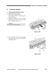
Removing the Scanning Lamp 1) Disconnect the power plug. 2) Remove the copyboard glass. (See Chapter 7.III.C.1. then, remove the screw [4], and detach the reflecting plate [5]. Figure 3-347 [4] [5] [3] [2] Figure 3-348 COPYRIGHT © 1999 CANON INC. C. Exposure System 1. CHAPTER 3 EXPOSURE SYSTEM [1] 4) Free the harness [3] from the guide [2]; "Removing the Copyboard Glass.") 3) Holding the middle of the No. 1 mirror...
Removing the Scanning Lamp 1) Disconnect the power plug. 2) Remove the copyboard glass. (See Chapter 7.III.C.1. then, remove the screw [4], and detach the reflecting plate [5]. Figure 3-347 [4] [5] [3] [2] Figure 3-348 COPYRIGHT © 1999 CANON INC. C. Exposure System 1. CHAPTER 3 EXPOSURE SYSTEM [1] 4) Free the harness [3] from the guide [2]; "Removing the Copyboard Glass.") 3) Holding the middle of the No. 1 mirror...

Service Manual
Page 88
CHAPTER 3 EXPOSURE SYSTEM 5) While pushing the electrode mount [6] found at the rear of the machine in the direction of the scanning lamp. 3. CANON PC800s/900s REV.0 AUG. 1999 PRINTED IN JAPAN (IMPRIME AU JAPON) Caution: 1. Do not start the work if the scanning lamp is soiled, dry wipe it. [6] [7] Figure 3-349 3-38 COPYRIGHT © 1999 CANON INC. Do not leave fingerprints on the sur- face of the arrow, detach the scanning lamp [7]. If the surface of the scanning lamp is hot. 2.
CHAPTER 3 EXPOSURE SYSTEM 5) While pushing the electrode mount [6] found at the rear of the machine in the direction of the scanning lamp. 3. CANON PC800s/900s REV.0 AUG. 1999 PRINTED IN JAPAN (IMPRIME AU JAPON) Caution: 1. Do not start the work if the scanning lamp is soiled, dry wipe it. [6] [7] Figure 3-349 3-38 COPYRIGHT © 1999 CANON INC. Do not leave fingerprints on the sur- face of the arrow, detach the scanning lamp [7]. If the surface of the scanning lamp is hot. 2.
Service Manual
Page 89
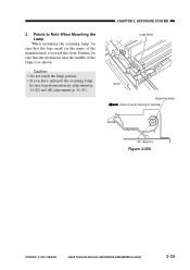
...: • Do not touch the lamp portion. • If you have replaced the scanning lamp, be sure that the protrusion near the middle of the manufacturer) is as shown. CHAPTER 3 EXPOSURE SYSTEM Logo mark (front) Scanning lamp (mirror mount moving in reverse) 45 (approx.) Figure 3-350 COPYRIGHT © 1999 CANON INC. 2. Further, be sure that...
...: • Do not touch the lamp portion. • If you have replaced the scanning lamp, be sure that the protrusion near the middle of the manufacturer) is as shown. CHAPTER 3 EXPOSURE SYSTEM Logo mark (front) Scanning lamp (mirror mount moving in reverse) 45 (approx.) Figure 3-350 COPYRIGHT © 1999 CANON INC. 2. Further, be sure that...

Service Manual
Page 121
... Figure 4-204 [5] [4] Caution: When mounting the blanking exposure unit, check to make sure that the blanking exposure unit PCBs are at the extreme ends and that the lens is positioned at the farthest left (141% position). [3] Figure 4-205 Lamp PCBs Figure 4-206 COPYRIGHT © 1999 CANON INC. CHAPTER 4 IMAGE FORMATION SYSTEM 7) Open the machine...
... Figure 4-204 [5] [4] Caution: When mounting the blanking exposure unit, check to make sure that the blanking exposure unit PCBs are at the extreme ends and that the lens is positioned at the farthest left (141% position). [3] Figure 4-205 Lamp PCBs Figure 4-206 COPYRIGHT © 1999 CANON INC. CHAPTER 4 IMAGE FORMATION SYSTEM 7) Open the machine...
Service Manual
Page 347
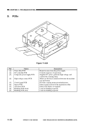
..., and controls the scanning lamp. Provides copying insurrections/indications. Detects paper in front of operations. Used for blanking exposure. Controls sequence of the registration roller. CHAPTER 11 TROUBLESHOOTING D. PCBs [9] [3] [4] [1] [7] [8] [5] [2] [6] Figure 11-604 Ref. Used for blanking exposure. 11-82 COPYRIGHT © 1999 CANON INC. Name [1] Noise filter...from the power supply. Detects the density of originals. Makes an electrical connection between the machine top and bottom. CANON PC800s/900s REV.0 AUG. 1999 PRINTED IN JAPAN (IMPRIME AU JAPON)
..., and controls the scanning lamp. Provides copying insurrections/indications. Detects paper in front of operations. Used for blanking exposure. Controls sequence of the registration roller. CHAPTER 11 TROUBLESHOOTING D. PCBs [9] [3] [4] [1] [7] [8] [5] [2] [6] Figure 11-604 Ref. Used for blanking exposure. 11-82 COPYRIGHT © 1999 CANON INC. Name [1] Noise filter...from the power supply. Detects the density of originals. Makes an electrical connection between the machine top and bottom. CANON PC800s/900s REV.0 AUG. 1999 PRINTED IN JAPAN (IMPRIME AU JAPON)
Service Manual
Page 358
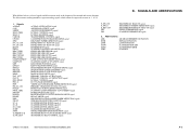
...signal POWER SWITCH OFF signal REGISTRATION CLUTCH SOLENOID DRIVE signal RELAY DRIVE signal PRE-REGISTRATION ROLLER PAPER DETECTION signal SIDE BLANK EXPOSURE LAMP ON signal SCANNER MOTOR PULSE signal A SCANNER MOTOR PULSE signal B SCANNER MOTOR DRIVE signal SCANNER HOME POSITION signal SINGLE... AER AE (MEASUREMENT) ROTATION INTR INITIAL ROTATION LSTR LAST ROTATION SCFW SCANNER FORWARD SCRV SCANNER REVERSE STBY STANDBY COPYRIGHT © 1999 CANON INC. What follows below is a list of signals and abbreviations used in the chapters of the manual and circuit diagrams. The ...
...signal POWER SWITCH OFF signal REGISTRATION CLUTCH SOLENOID DRIVE signal RELAY DRIVE signal PRE-REGISTRATION ROLLER PAPER DETECTION signal SIDE BLANK EXPOSURE LAMP ON signal SCANNER MOTOR PULSE signal A SCANNER MOTOR PULSE signal B SCANNER MOTOR DRIVE signal SCANNER HOME POSITION signal SINGLE... AER AE (MEASUREMENT) ROTATION INTR INITIAL ROTATION LSTR LAST ROTATION SCFW SCANNER FORWARD SCRV SCANNER REVERSE STBY STANDBY COPYRIGHT © 1999 CANON INC. What follows below is a list of signals and abbreviations used in the chapters of the manual and circuit diagrams. The ...
Service Manual
Page 360
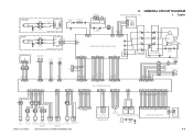
... LF1 2 2 FT1 FT3 1 1 J1 DS1 Door switch NF1 NOISE FILTER PCB Thermal fuse 1 FU1 Scanning lamp LA1 J17 FT6 FT5 Fixing heater H1 J16 1 2 J15 J2 FU2 Thermal fuse 2 J434 11 22 C. CANON PC800s/900s REV.0 AUG. 1999 PRINTED IN JAPAN (IMPRIME AU JAPON) J751 3 2 1 Q751 Pre-registration ...roller paper sensor SENSOR PCB M 12 12 J601 J602 M2 Scanner/lens drive motor SIDE BLANK EXPOSURE PCB 1 2 3 4 5 6 7 8 9 10 11 12 13 ...
... LF1 2 2 FT1 FT3 1 1 J1 DS1 Door switch NF1 NOISE FILTER PCB Thermal fuse 1 FU1 Scanning lamp LA1 J17 FT6 FT5 Fixing heater H1 J16 1 2 J15 J2 FU2 Thermal fuse 2 J434 11 22 C. CANON PC800s/900s REV.0 AUG. 1999 PRINTED IN JAPAN (IMPRIME AU JAPON) J751 3 2 1 Q751 Pre-registration ...roller paper sensor SENSOR PCB M 12 12 J601 J602 M2 Scanner/lens drive motor SIDE BLANK EXPOSURE PCB 1 2 3 4 5 6 7 8 9 10 11 12 13 ...


