
Service Manual
Page 3
.... This service manual consists of the following chapters: Chapter 1 General Description introduces the machine's features, specifications, names of parts, and how originals are made on a step-by -step instructions. Chapter 3 Exposure System discusses the principles of installation,... system. Chapter 2 Basic Operation explains how copies are reproduced. Appendix contains a general timing chart and general circuit diagrams. COPYRIGHT © 1999 CANON INC. Chapter 4 Image Formation System discusses the principles of operation used for the machine's fixing system. Chapter 6...
.... This service manual consists of the following chapters: Chapter 1 General Description introduces the machine's features, specifications, names of parts, and how originals are made on a step-by -step instructions. Chapter 3 Exposure System discusses the principles of installation,... system. Chapter 2 Basic Operation explains how copies are reproduced. Appendix contains a general timing chart and general circuit diagrams. COPYRIGHT © 1999 CANON INC. Chapter 4 Image Formation System discusses the principles of operation used for the machine's fixing system. Chapter 6...
Service Manual
Page 10
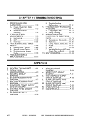
...11-75 B. ADF 11-83 F. ADF CONTROLLER CIRCUIT DIAGRAM A-15 F. AE SENSOR CIRCUIT DIAGRAM A-29 I . BLANK EXPOSURE (front) CIRCUIT DIAGRAM A-33 M. BLANK EXPOSURE (rear) CIRCUIT DIAGRAM A-34 N. SOLVENTS/OILS A-36 viii COPYRIGHT © 1999 CANON INC. STANDARDS AND ADJUSTMENTS 11-5 A. Mechanical 11-5 ... B. Sample Image Faults ....... 11-52 C. Troubleshooting Malfunctions 11-61 V. Faulty Feeding 11-78 VI. ARRANGEMENT AND FUNCTIONS OF ELECTRICAL PARTS 11-79 A. Switches 11-80 C. Lamp, Heater, Motor, Etc. 11-81 D. SELF DIAGNOSIS 11-86 APPENDIX A. GENERAL TIMING CHART...
...11-75 B. ADF 11-83 F. ADF CONTROLLER CIRCUIT DIAGRAM A-15 F. AE SENSOR CIRCUIT DIAGRAM A-29 I . BLANK EXPOSURE (front) CIRCUIT DIAGRAM A-33 M. BLANK EXPOSURE (rear) CIRCUIT DIAGRAM A-34 N. SOLVENTS/OILS A-36 viii COPYRIGHT © 1999 CANON INC. STANDARDS AND ADJUSTMENTS 11-5 A. Mechanical 11-5 ... B. Sample Image Faults ....... 11-52 C. Troubleshooting Malfunctions 11-61 V. Faulty Feeding 11-78 VI. ARRANGEMENT AND FUNCTIONS OF ELECTRICAL PARTS 11-79 A. Switches 11-80 C. Lamp, Heater, Motor, Etc. 11-81 D. SELF DIAGNOSIS 11-86 APPENDIX A. GENERAL TIMING CHART...
Service Manual
Page 41
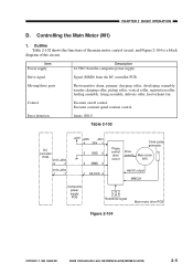
.... Error detection Issues 'E010'. CANON PC800s/900s REV.0 AUG. 1999 PRINTED IN JAPAN (IMPRIME AU JAPON) 2-5 CHAPTER 2 BASIC OPERATION D. Controlling the Main Motor (M1) 1. Moving/drive parts Photosensitive drum, primary charging roller, developing assembly, transfer charging roller, pickup roller, vertical roller, registration roller, feeding assembly, fixing assembly, delivery roller, heat ...Signal (MMD) from the composite power supply. Outline Table 2-102 shows the functions of the main motor control circuit, and Figure 2-104 is a block diagram of the circuit.
.... Error detection Issues 'E010'. CANON PC800s/900s REV.0 AUG. 1999 PRINTED IN JAPAN (IMPRIME AU JAPON) 2-5 CHAPTER 2 BASIC OPERATION D. Controlling the Main Motor (M1) 1. Moving/drive parts Photosensitive drum, primary charging roller, developing assembly, transfer charging roller, pickup roller, vertical roller, registration roller, feeding assembly, fixing assembly, delivery roller, heat ...Signal (MMD) from the composite power supply. Outline Table 2-102 shows the functions of the main motor control circuit, and Figure 2-104 is a block diagram of the circuit.
Service Manual
Page 255
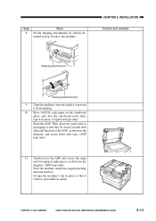
... attachment [2] 9 Tape the machine's top unit in place to the machine. then, tape it in place. (Copyboard type only) Raise the ADF. COPYRIGHT © 1999 CANON INC. Or tape the machine's top in place so that they fit closely around both sides and the front of the ADF, as shown in... secure the main unit by taping in eight places, as packaging so that it will not open while in transit. Then, place two parts used as shown in the diagram. (ADF type only) Pack the machine, using the original packing material and box. Step 8 Work Fit the shipping attachments [1] and [2] detached in...
... attachment [2] 9 Tape the machine's top unit in place to the machine. then, tape it in place. (Copyboard type only) Raise the ADF. COPYRIGHT © 1999 CANON INC. Or tape the machine's top in place so that they fit closely around both sides and the front of the ADF, as shown in... secure the main unit by taping in eight places, as packaging so that it will not open while in transit. Then, place two parts used as shown in the diagram. (ADF type only) Pack the machine, using the original packing material and box. Step 8 Work Fit the shipping attachments [1] and [2] detached in...


