

Service Manual
Page 2
... ACTUAL MACHINE VALUES OR THOSE FOUND IN ADVERTISING AND OTHER PRINTED MATTER. THIS DOCUMENTATION IS INTENDED FOR ALL SALES AREAS, AND MAY CONTAIN INFORMATION NOT APPLICABLE TO CERTAIN AREAS. CANON PC800s/900s REV.0 AUG. 1999 PRINTED IN JAPAN (IMPRIME AU JAPON) ANY QUESTIONS REGARDING INFORMATION CONTAINED HEREIN SHOULD BE DIRECTED TO THE COPIER SERVICE DEPARTMENT OF THE SALES COMPANY...
... ACTUAL MACHINE VALUES OR THOSE FOUND IN ADVERTISING AND OTHER PRINTED MATTER. THIS DOCUMENTATION IS INTENDED FOR ALL SALES AREAS, AND MAY CONTAIN INFORMATION NOT APPLICABLE TO CERTAIN AREAS. CANON PC800s/900s REV.0 AUG. 1999 PRINTED IN JAPAN (IMPRIME AU JAPON) ANY QUESTIONS REGARDING INFORMATION CONTAINED HEREIN SHOULD BE DIRECTED TO THE COPIER SERVICE DEPARTMENT OF THE SALES COMPANY...
Service Manual
Page 3
... be installed using step-by -step basis. Chapter 2 Basic Operation explains how copies are reproduced. Chapter 6 Fixing System discusses the principles of operation used for the machine's pickup/feeding system. Chapter 11 Troubleshooting provides tables of periodically replaced parts and consumables/durables and scheduled servicing charts. Chapter 10 Maintenance and Servicing provides tables of maintenance/inspection, standards/ adjustments, and problem identification (image fault/malfunction). INTRODUCTION This service manual has...
... be installed using step-by -step basis. Chapter 2 Basic Operation explains how copies are reproduced. Chapter 6 Fixing System discusses the principles of operation used for the machine's pickup/feeding system. Chapter 11 Troubleshooting provides tables of periodically replaced parts and consumables/durables and scheduled servicing charts. Chapter 10 Maintenance and Servicing provides tables of maintenance/inspection, standards/ adjustments, and problem identification (image fault/malfunction). INTRODUCTION This service manual has...
Service Manual
Page 8
... CANON INC. Delivery Assembly 5-36 CHAPTER 6 FIXING SYSTEM I . Outline 6-1 B. Controlling the Primary Charging Roller Bias 4-4 D. Controlling the Developing/ Separation Static Eliminator Bias 4-11 F. Measuring the Density of Paper 5-9 D. Blank Exposure 4-26 CHAPTER 5 PICK-UP/FEEDING SYSTEM I . Outline 5-1 B. Pickup Assembly 5-19 B. CANON PC800s/900s REV.0 AUG. 1999 PRINTED IN JAPAN (IMPRIME AU JAPON) Controlling the Transfer Roller Bias 4-8 E. DISASSEMBLY/ASSEMBLY ..... 4-22 A. Cartridge 4-23 B. OPERATIONS...
... CANON INC. Delivery Assembly 5-36 CHAPTER 6 FIXING SYSTEM I . Outline 6-1 B. Controlling the Primary Charging Roller Bias 4-4 D. Controlling the Developing/ Separation Static Eliminator Bias 4-11 F. Measuring the Density of Paper 5-9 D. Blank Exposure 4-26 CHAPTER 5 PICK-UP/FEEDING SYSTEM I . Outline 5-1 B. Pickup Assembly 5-19 B. CANON PC800s/900s REV.0 AUG. 1999 PRINTED IN JAPAN (IMPRIME AU JAPON) Controlling the Transfer Roller Bias 4-8 E. DISASSEMBLY/ASSEMBLY ..... 4-22 A. Cartridge 4-23 B. OPERATIONS...
Service Manual
Page 10
... TOOLS A-35 O. MAINTENANCE AND INSPECTION 11-3 A. Sample Image Faults ....... 11-52 C. TROUBLESHOOTING FEEDING PROBLEMS 11-75 A. ARRANGEMENT AND FUNCTIONS OF ELECTRICAL PARTS 11-79 A. PCBs 11-82 E. DC CONTROLLER CIRCUIT DIAGRAM A-7 E. SENSOR CIRCUIT DIAGRAM A-30 J. Troubleshooting Image Faults 11-53 IV. ADF 11-83 F. AE SENSOR CIRCUIT DIAGRAM A-29 I . BLANK EXPOSURE (front) CIRCUIT DIAGRAM A-33 M. CANON PC800s/900s REV.0 AUG. 1999 PRINTED IN JAPAN (IMPRIME...
... TOOLS A-35 O. MAINTENANCE AND INSPECTION 11-3 A. Sample Image Faults ....... 11-52 C. TROUBLESHOOTING FEEDING PROBLEMS 11-75 A. ARRANGEMENT AND FUNCTIONS OF ELECTRICAL PARTS 11-79 A. PCBs 11-82 E. DC CONTROLLER CIRCUIT DIAGRAM A-7 E. SENSOR CIRCUIT DIAGRAM A-30 J. Troubleshooting Image Faults 11-53 IV. ADF 11-83 F. AE SENSOR CIRCUIT DIAGRAM A-29 I . BLANK EXPOSURE (front) CIRCUIT DIAGRAM A-33 M. CANON PC800s/900s REV.0 AUG. 1999 PRINTED IN JAPAN (IMPRIME...

Service Manual
Page 13
... performs simple replacement/cleaning work immediately after power-on the average, 0.02 ppm or less at maximum (1/100 to make jam removal easy. 8. CANON PC800s/900s REV.0 AUG. 1999 PRINTED IN JAPAN (IMPRIME AU JAPON) 1-1 CHAPTER 1 GENERAL DESCRIPTION I. Ecology-Conscious • The use of the ADF. Personal Copier with the use of a roller charging method has resulted in a considerable reduction of paper (500-sheet...
... performs simple replacement/cleaning work immediately after power-on the average, 0.02 ppm or less at maximum (1/100 to make jam removal easy. 8. CANON PC800s/900s REV.0 AUG. 1999 PRINTED IN JAPAN (IMPRIME AU JAPON) 1-1 CHAPTER 1 GENERAL DESCRIPTION I. Ecology-Conscious • The use of the ADF. Personal Copier with the use of a roller charging method has resulted in a considerable reduction of paper (500-sheet...

Service Manual
Page 27
... copying. Turns on when indicating a ratio. 100 (max.; CANON PC800s/900s REV.0 AUG. 1999 PRINTED IN JAPAN (IMPRIME AU JAPON) 1-15 USING THE MACHINE A. Indicates the selected default ratio. continuous copying) Stops copying or returns copying mode to a jam. • Indicates the number of copies manually. Name 1 Copy density adjusting lever 2 Copy density mode indicator 3 Default ratio indicator 4 Paper selection indicator*1 5 Jam indicator 6 Count/ratio indicator 7 Clear/stop key 8 Copy start key 9 Power switch...
... copying. Turns on when indicating a ratio. 100 (max.; CANON PC800s/900s REV.0 AUG. 1999 PRINTED IN JAPAN (IMPRIME AU JAPON) 1-15 USING THE MACHINE A. Indicates the selected default ratio. continuous copying) Stops copying or returns copying mode to a jam. • Indicates the number of copies manually. Name 1 Copy density adjusting lever 2 Copy density mode indicator 3 Default ratio indicator 4 Paper selection indicator*1 5 Jam indicator 6 Count/ratio indicator 7 Clear/stop key 8 Copy start key 9 Power switch...

Service Manual
Page 37
... OPERATIONS A. Control system Control panel Exposure system Copyboard Control circuit Original illuminating block Optical block Primary charging roller Image formation system Drum cleaning block Photosensitive drum Developing assembly Copy tray Feeding Fixing assembly/ delivery assembly Transfer/ separation Cassette Figure 2-101 Pickup control block Manual feed block Pickup/ feeding system COPYRIGHT © 1999 CANON INC. Functional Construction The machine consists of four functional blocks: pickup/feeding system, exposure...
... OPERATIONS A. Control system Control panel Exposure system Copyboard Control circuit Original illuminating block Optical block Primary charging roller Image formation system Drum cleaning block Photosensitive drum Developing assembly Copy tray Feeding Fixing assembly/ delivery assembly Transfer/ separation Cassette Figure 2-101 Pickup control block Manual feed block Pickup/ feeding system COPYRIGHT © 1999 CANON INC. Functional Construction The machine consists of four functional blocks: pickup/feeding system, exposure...
Service Manual
Page 117
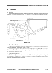
... shutter is removed from the machine, light makes its way through the opening used to protect the photosensitive drum from light. To prevent photo memory, the machine is closed. b. Cartridge 1. Drum Cover Shutter If exposed to as a "cartridge." (You cannot disassemble the cartridge.) Developing blade Primary charging roller Light-blocking shutter Photosensitive drum Cleaning blade Drum cover shutter Developing cylinder Figure 4-201 a. CANON PC800s/900s REV.0 AUG. 1999 PRINTED IN JAPAN...
... shutter is removed from the machine, light makes its way through the opening used to protect the photosensitive drum from light. To prevent photo memory, the machine is closed. b. Cartridge 1. Drum Cover Shutter If exposed to as a "cartridge." (You cannot disassemble the cartridge.) Developing blade Primary charging roller Light-blocking shutter Photosensitive drum Cleaning blade Drum cover shutter Developing cylinder Figure 4-201 a. CANON PC800s/900s REV.0 AUG. 1999 PRINTED IN JAPAN...
Service Manual
Page 142
... in mind: 1. ! A few of its part removed. 7. DISASSEMBLY/ASSEMBLY As needed, disassemble/assemble the machine with a washer to disassemble it. 3. As a rule, do not operate the machine with any screws indiscriminately. 5-18 COPYRIGHT © 1999 CANON INC. Before starting the work, turn off the power switch and disconnect the power plug for safety. 2. Use the washers where necessary. (The screws used to ensure electrical continuity.) 5.
... in mind: 1. ! A few of its part removed. 7. DISASSEMBLY/ASSEMBLY As needed, disassemble/assemble the machine with a washer to disassemble it. 3. As a rule, do not operate the machine with any screws indiscriminately. 5-18 COPYRIGHT © 1999 CANON INC. Before starting the work, turn off the power switch and disconnect the power plug for safety. 2. Use the washers where necessary. (The screws used to ensure electrical continuity.) 5.

Service Manual
Page 254
... power plug from the outlet. Step 1 2 3 4 5 Work Checks and remarks Turn on the manual feed tray. then, press the Copy Start key without placing any other means of the machine, and open the machine's top unit. CANON PC800s/900s REV.0 AUG. 1999 PRINTED IN JAPAN (IMPRIME AU JAPON) If it is, as immediately after installation, be able to make sure that the machines is replaced. Press the Paper...
... power plug from the outlet. Step 1 2 3 4 5 Work Checks and remarks Turn on the manual feed tray. then, press the Copy Start key without placing any other means of the machine, and open the machine's top unit. CANON PC800s/900s REV.0 AUG. 1999 PRINTED IN JAPAN (IMPRIME AU JAPON) If it is, as immediately after installation, be able to make sure that the machines is replaced. Press the Paper...
Service Manual
Page 258
III. CHAPTER 10 MAINTENANCE AND SERVICING I. COPYRIGHT © 1999 CANON INC. II. CANON PC800s/900s REV.0 AUG. 1999 PRINTED IN JAPAN (IMPRIME AU JAPON) 10-1 SCHEDULED SERVICING The machine does not have parts which require scheduled servicing. PERIODICALLY REPLACED PARTS The machine does not have any parts which must be replaced on a periodical basis. DURABLES AND CONSUMABLES The machine does not have items designated as durables or consumables.
III. CHAPTER 10 MAINTENANCE AND SERVICING I. COPYRIGHT © 1999 CANON INC. II. CANON PC800s/900s REV.0 AUG. 1999 PRINTED IN JAPAN (IMPRIME AU JAPON) 10-1 SCHEDULED SERVICING The machine does not have parts which require scheduled servicing. PERIODICALLY REPLACED PARTS The machine does not have any parts which must be replaced on a periodical basis. DURABLES AND CONSUMABLES The machine does not have items designated as durables or consumables.
Service Manual
Page 262
... white spots or vertical bands. CHAPTER 10 MAINTENANCE AND SERVICING c. Do not clean it outside the machine unprotected. g. CANON PC800s/900s REV.0 AUG. 1999 PRINTED IN JAPAN (IMPRIME AU JAPON) 10-5 Make sure that it . If the cartridge must be taken out of 1500 lux (general lighting) for the photosensitive drum shutter. The photosensitive drum is as strong as a means of...
... white spots or vertical bands. CHAPTER 10 MAINTENANCE AND SERVICING c. Do not clean it outside the machine unprotected. g. CANON PC800s/900s REV.0 AUG. 1999 PRINTED IN JAPAN (IMPRIME AU JAPON) 10-5 Make sure that it . If the cartridge must be taken out of 1500 lux (general lighting) for the photosensitive drum shutter. The photosensitive drum is as strong as a means of...
Service Manual
Page 264
... to Note for Servicing 11-4 II. TROUBLESHOOTING FEEDING PROBLEMS 11-75 A. ARRANGEMENT AND FUNCTIONS OF ELECTRICAL PARTS 11-79 A. CANON PC800s/900s REV.0 AUG. 1999 PRINTED IN JAPAN (IMPRIME AU JAPON) STANDARDS AND ADJUSTMENTS 11-5 A. SELF DIAGNOSIS 11-86 COPYRIGHT © 1999 CANON INC. Image Adjustment Basic Procedure 11-3 B. Copy Paper Jam 11-75 B. ADF 11-30 C. Troubleshooting Image Faults 11-53...
... to Note for Servicing 11-4 II. TROUBLESHOOTING FEEDING PROBLEMS 11-75 A. ARRANGEMENT AND FUNCTIONS OF ELECTRICAL PARTS 11-79 A. CANON PC800s/900s REV.0 AUG. 1999 PRINTED IN JAPAN (IMPRIME AU JAPON) STANDARDS AND ADJUSTMENTS 11-5 A. SELF DIAGNOSIS 11-86 COPYRIGHT © 1999 CANON INC. Image Adjustment Basic Procedure 11-3 B. Copy Paper Jam 11-75 B. ADF 11-30 C. Troubleshooting Image Faults 11-53...
Service Manual
Page 318
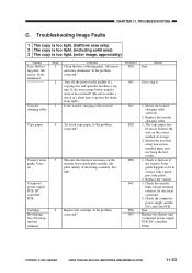
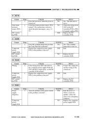
... copy paper. Is it 0Ω? Mount the transfer charging roller correctly. 2. The copy paper may not bring the best results. 1. Inform the user that using non-recommended paper may be in the middle of the fixing assembly. Replace the electric unit (composite power supply PCB, DC controller PCB). COPYRIGHT © 1999 CANON INC. Troubleshooting Image Faults 1 The copy is too light. (halftone area only) 2 The copy is too light...
... copy paper. Is it 0Ω? Mount the transfer charging roller correctly. 2. The copy paper may not bring the best results. 1. Inform the user that using non-recommended paper may be in the middle of the fixing assembly. Replace the electric unit (composite power supply PCB, DC controller PCB). COPYRIGHT © 1999 CANON INC. Troubleshooting Image Faults 1 The copy is too light. (halftone area only) 2 The copy is too light...
Service Manual
Page 319
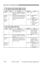
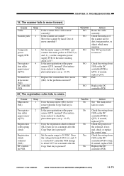
... problem corrected? End. Turn off the power in the middle of the drum and the machine's top unit? YES 1. Replace the cartridge. 2. Replace the transfer charging roller correctly. 6 The copy is still foggy, to the middle setting, and make a copy. Is there electrical continuity between the PCB of the base of a copying run, and open the machine. Check the activation of the scanning lamp. 2. CANON PC800s/900s REV.0 AUG. 1999 PRINTED...
... problem corrected? End. Turn off the power in the middle of the drum and the machine's top unit? YES 1. Replace the cartridge. 2. Replace the transfer charging roller correctly. 6 The copy is still foggy, to the middle setting, and make a copy. Is there electrical continuity between the PCB of the base of a copying run, and open the machine. Check the activation of the scanning lamp. 2. CANON PC800s/900s REV.0 AUG. 1999 PRINTED...
Service Manual
Page 320
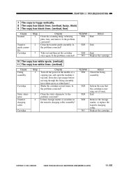
.... (vertical) Cause Fixing assembly Cartridge Step 1 2 Checks Turn off the power in the transfer charging roller assembly? YES Inform the user that the cartridge is foggy vertically. 8 The copy has black lines. (vertical, fuzzy, thick) 9 The copy has black lines. (vertical, fine) Cause Scanner Transfer guide assembly Cartridge Step 1 2 Checks Clean the scanning lamp, reflecting plate, lens, and mirror. NO Replace the cartridge. CANON PC800s/900s REV.0 AUG. 1999 PRINTED IN JAPAN...
.... (vertical) Cause Fixing assembly Cartridge Step 1 2 Checks Turn off the power in the transfer charging roller assembly? YES Inform the user that the cartridge is foggy vertically. 8 The copy has black lines. (vertical, fuzzy, thick) 9 The copy has black lines. (vertical, fine) Cause Scanner Transfer guide assembly Cartridge Step 1 2 Checks Clean the scanning lamp, reflecting plate, lens, and mirror. NO Replace the cartridge. CANON PC800s/900s REV.0 AUG. 1999 PRINTED IN JAPAN...
Service Manual
Page 324
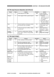
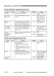
... 1 2 3 4 5 6 Checks Is the cartridge set in Direct within specification? YES Check the highvoltage transformer (composite power supply PCB). Does the lens move smoothly? Check the lens rail for electrical continuity. 2. Is the primary charging terminal on the power switch. NO 1. CANON PC800s/900s REV.0 AUG. 1999 PRINTED IN JAPAN (IMPRIME AU JAPON) 11-59 Clean the scanning lamp, reflecting plate, mirror, and lens. Instruct the user...
... 1 2 3 4 5 6 Checks Is the cartridge set in Direct within specification? YES Check the highvoltage transformer (composite power supply PCB). Does the lens move smoothly? Check the lens rail for electrical continuity. 2. Is the primary charging terminal on the power switch. NO 1. CANON PC800s/900s REV.0 AUG. 1999 PRINTED IN JAPAN (IMPRIME AU JAPON) 11-59 Clean the scanning lamp, reflecting plate, mirror, and lens. Instruct the user...
Service Manual
Page 330
... Cause Power supply frequency Composite power supply PCB Step 1 Checks Turn off and then on how to check the photointerrupers, see p. 1147.) YES/NO NO NO YES Action See "The lens fails to use a frequency stabilizer. CANON PC800s/900s REV.0 AUG. 1999 PRINTED IN JAPAN (IMPRIME AU JAPON) 11-65 CHAPTER 11 TROUBLESHOOTING 8 E210 Cause Lens home position sensor (PS2...
... Cause Power supply frequency Composite power supply PCB Step 1 Checks Turn off and then on how to check the photointerrupers, see p. 1147.) YES/NO NO NO YES Action See "The lens fails to use a frequency stabilizer. CANON PC800s/900s REV.0 AUG. 1999 PRINTED IN JAPAN (IMPRIME AU JAPON) 11-65 CHAPTER 11 TROUBLESHOOTING 8 E210 Cause Lens home position sensor (PS2...
Service Manual
Page 336
... PCB change to Q751; No Check the position of the scanner rail for a moment after the Copy Start key is pressed? if normal, check or replace the control ring. CANON PC800s/900s REV.0 AUG. 1999 PRINTED IN JAPAN (IMPRIME AU JAPON) 11-71 CHAPTER 11 TROUBLESHOOTING 19 The scanner fails to rotate. Does it move forward. See "DC power fails to turn...
... PCB change to Q751; No Check the position of the scanner rail for a moment after the Copy Start key is pressed? if normal, check or replace the control ring. CANON PC800s/900s REV.0 AUG. 1999 PRINTED IN JAPAN (IMPRIME AU JAPON) 11-71 CHAPTER 11 TROUBLESHOOTING 19 The scanner fails to rotate. Does it move forward. See "DC power fails to turn...
Service Manual
Page 339
... cassette set correctly? Set the meter range to 30 VDC, and connect the meter probes to turn on." Is the vertical path roller paper sensor (PS4) normal? (For instructions on the composite power PCB. See "The DC power fails to J202-2 (+) and -1 (-) on how to check the photointerrupters, see p. 11-47.) YES/NO YES NO YES Action Remove the jam paper. if normal, replace...
... cassette set correctly? Set the meter range to 30 VDC, and connect the meter probes to turn on." Is the vertical path roller paper sensor (PS4) normal? (For instructions on the composite power PCB. See "The DC power fails to J202-2 (+) and -1 (-) on how to check the photointerrupters, see p. 11-47.) YES/NO YES NO YES Action Remove the jam paper. if normal, replace...


