
Service Manual
Page 8
...4-1 B. Blank Exposure 4-26 CHAPTER 5 PICK-UP/FEEDING SYSTEM I . Controlling the Fixing Temperature 6-3 II. DISASSEMBLY/ASSEMBLY ..... 4-22 A. Cartridge 4-23 B. Multifeeder Assembly ......... 5-28 C. Controlling the Primary Charging Roller Bias 4-4 D. DISASSEMBLY/ASSEMBLY ..... 5-18 A. Single-feeder Assembly ........ FORMATION SYSTEM I. Registration Roller Assembly 5-34 F. Controlling the Side Blanking Mechanism 4-21 II. OPERATIONS 6-1 A. CANON PC800s/900s REV.0 AUG. 1999 PRINTED IN JAPAN (IMPRIME AU JAPON) Controlling the Developing/ Separation Static Eliminator Bias...
...4-1 B. Blank Exposure 4-26 CHAPTER 5 PICK-UP/FEEDING SYSTEM I . Controlling the Fixing Temperature 6-3 II. DISASSEMBLY/ASSEMBLY ..... 4-22 A. Cartridge 4-23 B. Multifeeder Assembly ......... 5-28 C. Controlling the Primary Charging Roller Bias 4-4 D. DISASSEMBLY/ASSEMBLY ..... 5-18 A. Single-feeder Assembly ........ FORMATION SYSTEM I. Registration Roller Assembly 5-34 F. Controlling the Side Blanking Mechanism 4-21 II. OPERATIONS 6-1 A. CANON PC800s/900s REV.0 AUG. 1999 PRINTED IN JAPAN (IMPRIME AU JAPON) Controlling the Developing/ Separation Static Eliminator Bias...

Service Manual
Page 9
...8-1 A. Controlling the Belt Motor .. 8-15 I . DISASSEMBLY/ASSEMBLY ..... 8-18 A. SELECTING A SITE 9-1 II. Storing and Handling the Cartridge with the Packaging Seal Intact ........ 10-2 B. Outline of the Power Supply System 7-3 B. External Covers 7-8 B. Electrical System 7-21 CHAPTER 8...Unpacking and Installation ....9-2 B. MOVING THE MACHINE .......... 9-12 CHAPTER 10 MAINTENANCE AND SERVICING I . STORING AND HANDLING THE CARTRIDGE 10-2 A. CANON PC800s/900s REV.0 AUG. 1999 PRINTED IN JAPAN (IMPRIME AU JAPON) vii DISASSEMBLY/ASSEMBLY ........7-7 A. Detecting an Original...
...8-1 A. Controlling the Belt Motor .. 8-15 I . DISASSEMBLY/ASSEMBLY ..... 8-18 A. SELECTING A SITE 9-1 II. Storing and Handling the Cartridge with the Packaging Seal Intact ........ 10-2 B. Outline of the Power Supply System 7-3 B. External Covers 7-8 B. Electrical System 7-21 CHAPTER 8...Unpacking and Installation ....9-2 B. MOVING THE MACHINE .......... 9-12 CHAPTER 10 MAINTENANCE AND SERVICING I . STORING AND HANDLING THE CARTRIDGE 10-2 A. CANON PC800s/900s REV.0 AUG. 1999 PRINTED IN JAPAN (IMPRIME AU JAPON) vii DISASSEMBLY/ASSEMBLY ........7-7 A. Detecting an Original...

Service Manual
Page 13
... The photosensitive drum, toner case, charging roller, developing assembly, and cleaning assembly are constructed as a business card. 5. COPYRIGHT © 1999 CANON INC. CANON PC800s/900s REV.0 AUG. 1999 PRINTED IN JAPAN (IMPRIME AU JAPON) 1-1 Personal Copier with the use of paper (500-sheet cassette + multifeeder...removal easy. 8. Various Paper Sizes • The paper may be as large as A4 (LGL) or as small as a single entity (cartridge). SURF Fixing Assembly • The wait time is possible with a Zoom Function and a Fixed Copyboard • You can choose either a ...
... The photosensitive drum, toner case, charging roller, developing assembly, and cleaning assembly are constructed as a business card. 5. COPYRIGHT © 1999 CANON INC. CANON PC800s/900s REV.0 AUG. 1999 PRINTED IN JAPAN (IMPRIME AU JAPON) 1-1 Personal Copier with the use of paper (500-sheet cassette + multifeeder...removal easy. 8. Various Paper Sizes • The paper may be as large as A4 (LGL) or as small as a single entity (cartridge). SURF Fixing Assembly • The wait time is possible with a Zoom Function and a Fixed Copyboard • You can choose either a ...

Service Manual
Page 93
... FORMATION SYSTEM This chapter discusses the principles of Originals 4-16 G. DISASSEMBLY/ASSEMBLY ..... 4-22 A. Outline 4-1 B. Timing Chart for the Image Formation System 4-3 C. Cartridge 4-23 B. Transfer Charging Assembly 4-25 C. IMAGE FORMATION SYSTEM ...4-1 A. CANON PC800s/900s REV.0 AUG. 1999 PRINTED IN JAPAN (IMPRIME AU JAPON) Controlling the Developing/ Separation Static Eliminator Bias 4-11 F. Measuring the...
... FORMATION SYSTEM This chapter discusses the principles of Originals 4-16 G. DISASSEMBLY/ASSEMBLY ..... 4-22 A. Outline 4-1 B. Timing Chart for the Image Formation System 4-3 C. Cartridge 4-23 B. Transfer Charging Assembly 4-25 C. IMAGE FORMATION SYSTEM ...4-1 A. CANON PC800s/900s REV.0 AUG. 1999 PRINTED IN JAPAN (IMPRIME AU JAPON) Controlling the Developing/ Separation Static Eliminator Bias 4-11 F. Measuring the...
Service Manual
Page 96
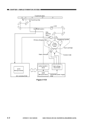
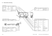
CHAPTER 4 IMAGE FORMATION SYSTEM Copyboard glass Scanning lamp AE sensor Side blanking lamp Lens Primary charging roller Developing cylinder Photosensitive drum Drum cartridge Static eliminator Transfer roller Q101 Microprocessor DC controller PCB Lamp regulator block High-voltage circuit block Q900 Microprocessor Composite power supply PCB Figure 4-101 4-2 COPYRIGHT © 1999 CANON INC. CANON PC800s/900s REV.0 AUG. 1999 PRINTED IN JAPAN (IMPRIME AU JAPON)
CHAPTER 4 IMAGE FORMATION SYSTEM Copyboard glass Scanning lamp AE sensor Side blanking lamp Lens Primary charging roller Developing cylinder Photosensitive drum Drum cartridge Static eliminator Transfer roller Q101 Microprocessor DC controller PCB Lamp regulator block High-voltage circuit block Q900 Microprocessor Composite power supply PCB Figure 4-101 4-2 COPYRIGHT © 1999 CANON INC. CANON PC800s/900s REV.0 AUG. 1999 PRINTED IN JAPAN (IMPRIME AU JAPON)
Service Manual
Page 117
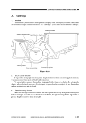
...open the shutter unless absolutely necessary. b. CANON PC800s/900s REV.0 AUG. 1999 PRINTED IN JAPAN (IMPRIME AU JAPON) 4-23 To prevent photo memory, the machine is closed. As in a single container referred to expose images. Cartridge 1. CHAPTER 4 IMAGE FORMATION SYSTEM A. ... protect the photosensitive drum from the machine, light makes its way through the opening used to as a "cartridge." (You cannot disassemble the cartridge.) Developing blade Primary charging roller Light-blocking shutter Photosensitive drum Cleaning blade Drum cover shutter Developing cylinder Figure 4-...
...open the shutter unless absolutely necessary. b. CANON PC800s/900s REV.0 AUG. 1999 PRINTED IN JAPAN (IMPRIME AU JAPON) 4-23 To prevent photo memory, the machine is closed. As in a single container referred to expose images. Cartridge 1. CHAPTER 4 IMAGE FORMATION SYSTEM A. ... protect the photosensitive drum from the machine, light makes its way through the opening used to as a "cartridge." (You cannot disassemble the cartridge.) Developing blade Primary charging roller Light-blocking shutter Photosensitive drum Cleaning blade Drum cover shutter Developing cylinder Figure 4-...

Service Manual
Page 118
Cleaning the Drum Caution: As a rule, do not touch or clean the photosensitive drum. 1) Open the machine's top unit, and take out the cartridge. 2) Turn over the cartridge, and open the drum cover shutter 3) Clean the drum surface with a flannel cloth coated with toner. If you must clean it, use paper, lint... lighting) for 5 min and then is left alone for an appreciable time, the images will be sure to 30000 lux. 4-24 COPYRIGHT © 1999 CANON INC. CANON PC800s/900s REV.0 AUG. 1999 PRINTED IN JAPAN (IMPRIME AU JAPON) Do not use a flannel cloth. CHAPTER 4 IMAGE FORMATION SYSTEM 2.
Cleaning the Drum Caution: As a rule, do not touch or clean the photosensitive drum. 1) Open the machine's top unit, and take out the cartridge. 2) Turn over the cartridge, and open the drum cover shutter 3) Clean the drum surface with a flannel cloth coated with toner. If you must clean it, use paper, lint... lighting) for 5 min and then is left alone for an appreciable time, the images will be sure to 30000 lux. 4-24 COPYRIGHT © 1999 CANON INC. CANON PC800s/900s REV.0 AUG. 1999 PRINTED IN JAPAN (IMPRIME AU JAPON) Do not use a flannel cloth. CHAPTER 4 IMAGE FORMATION SYSTEM 2.
Service Manual
Page 120
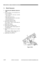
CANON PC800s/900s REV.0 AUG. 1999 PRINTED IN JAPAN (IMPRIME AU JAPON) Removing the Blanking Exposure Unit 1) Set the machine to the maximum ratio (141%) as ... left, turn off the power. • Disconnect the power plug. 2) Remove the front lower cover. (See Chapter 7.III.A.2."Removing the Front Lower Cover.") 3) Remove the cartridge. 4) Remove the DC controller PCB. (See Chapter 7.III.E.1."Removing the DC controller PCB.") 5) Remove the composite power supply PCB. (See Chapter 7.III.E.2."Removing the Composite...
CANON PC800s/900s REV.0 AUG. 1999 PRINTED IN JAPAN (IMPRIME AU JAPON) Removing the Blanking Exposure Unit 1) Set the machine to the maximum ratio (141%) as ... left, turn off the power. • Disconnect the power plug. 2) Remove the front lower cover. (See Chapter 7.III.A.2."Removing the Front Lower Cover.") 3) Remove the cartridge. 4) Remove the DC controller PCB. (See Chapter 7.III.E.1."Removing the DC controller PCB.") 5) Remove the composite power supply PCB. (See Chapter 7.III.E.2."Removing the Composite...
Service Manual
Page 197
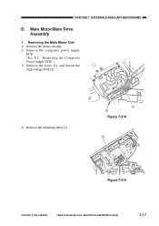
"Removing the Composite Power Supply PCB.") 3) Remove the screw [1], and detach the high-voltage PCB [2]. 4) Remove the insulating sheet [3]. [1] [2] Figure 7-318 [3] Figure 7-319 COPYRIGHT © 1999 CANON INC. CHAPTER 7 EXTERNALS/AUXILIARY MECHANISMS D. Removing the Main Motor Unit 1) Remove the drum cartridge. 2) Remove the composite power supply PCB. (See E.2. Main Motor/Main Drive Assembly 1. CANON PC800s/900s REV.0 AUG. 1999 PRINTED IN JAPAN (IMPRIME AU JAPON) 7-17
"Removing the Composite Power Supply PCB.") 3) Remove the screw [1], and detach the high-voltage PCB [2]. 4) Remove the insulating sheet [3]. [1] [2] Figure 7-318 [3] Figure 7-319 COPYRIGHT © 1999 CANON INC. CHAPTER 7 EXTERNALS/AUXILIARY MECHANISMS D. Removing the Main Motor Unit 1) Remove the drum cartridge. 2) Remove the composite power supply PCB. (See E.2. Main Motor/Main Drive Assembly 1. CANON PC800s/900s REV.0 AUG. 1999 PRINTED IN JAPAN (IMPRIME AU JAPON) 7-17
Service Manual
Page 199
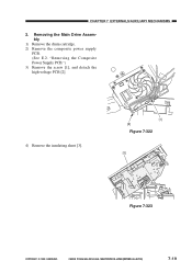
"Removing the Composite Power Supply PCB.") 3) Remove the screw [1], and detach the high-voltage PCB [2]. 4) Remove the insulating sheet [3]. [1] [2] Figure 7-322 [3] Figure 7-323 COPYRIGHT © 1999 CANON INC. CHAPTER 7 EXTERNALS/AUXILIARY MECHANISMS 2. CANON PC800s/900s REV.0 AUG. 1999 PRINTED IN JAPAN (IMPRIME AU JAPON) 7-19 Removing the Main Drive Assembly 1) Remove the drum cartridge. 2) Remove the composite power supply PCB. (See E.2.
"Removing the Composite Power Supply PCB.") 3) Remove the screw [1], and detach the high-voltage PCB [2]. 4) Remove the insulating sheet [3]. [1] [2] Figure 7-322 [3] Figure 7-323 COPYRIGHT © 1999 CANON INC. CHAPTER 7 EXTERNALS/AUXILIARY MECHANISMS 2. CANON PC800s/900s REV.0 AUG. 1999 PRINTED IN JAPAN (IMPRIME AU JAPON) 7-19 Removing the Main Drive Assembly 1) Remove the drum cartridge. 2) Remove the composite power supply PCB. (See E.2.
Service Manual
Page 247
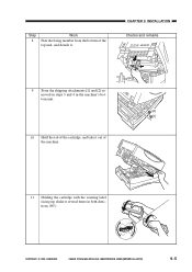
COPYRIGHT © 1999 CANON INC. CHAPTER 9 INSTALLATION Checks and remarks 9 Store the shipping attachments [1] and [2] removed in steps 3 and 4 in the machine's bottom unit. [2] [1] 10 Hold the tab of the cartridge, and take it out of the top unit, and detach it several times in both directions (90°). CANON PC800s/900s REV.0 AUG. 1999 PRINTED IN JAPAN (IMPRIME AU JAPON) 9-5 Step 8 Work Pick the fixing member from the bottom of the machine. 11 Holding the cartridge with the warning label facing up, shake it .
COPYRIGHT © 1999 CANON INC. CHAPTER 9 INSTALLATION Checks and remarks 9 Store the shipping attachments [1] and [2] removed in steps 3 and 4 in the machine's bottom unit. [2] [1] 10 Hold the tab of the cartridge, and take it out of the top unit, and detach it several times in both directions (90°). CANON PC800s/900s REV.0 AUG. 1999 PRINTED IN JAPAN (IMPRIME AU JAPON) 9-5 Step 8 Work Pick the fixing member from the bottom of the machine. 11 Holding the cartridge with the warning label facing up, shake it .
Service Manual
Page 248
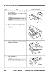
Checks and remarks 14 Push on the marking found on a level place, and pull off the open seal. Original tray 9-6 COPYRIGHT © 1999 CANON INC. CANON PC800s/900s REV.0 AUG. 1999 PRINTED IN JAPAN (IMPRIME AU JAPON) Caution: The seal can tear in the direction of the machine to the ADF ...type only. Do no pull it at an angle. 13 Hold the cartridge with the waning label facing up, and insert it into the machine with...
Checks and remarks 14 Push on the marking found on a level place, and pull off the open seal. Original tray 9-6 COPYRIGHT © 1999 CANON INC. CANON PC800s/900s REV.0 AUG. 1999 PRINTED IN JAPAN (IMPRIME AU JAPON) Caution: The seal can tear in the direction of the machine to the ADF ...type only. Do no pull it at an angle. 13 Hold the cartridge with the waning label facing up, and insert it into the machine with...
Service Manual
Page 257
Storing and Handling the Cartridge with the Packaging Seal Intact ........ 10-2 B. Storing the Cartridge with the Packaging Seal Removed 10-3 COPYRIGHT © 1999 CANON INC. CANON PC800s/900s REV.0 AUG. 1999 PRINTED IN JAPAN (IMPRIME AU JAPON) PERIODICALLY REPLACED PARTS 10-1 II. STORING AND HANDLING THE CARTRIDGE 10-2 A. DURABLES AND CONSUMABLES 10-1 III. CHAPTER 10 MAINTENANCE AND SERVICING I. SCHEDULED SERVICING ....... 10-1 IV.
Storing and Handling the Cartridge with the Packaging Seal Intact ........ 10-2 B. Storing the Cartridge with the Packaging Seal Removed 10-3 COPYRIGHT © 1999 CANON INC. CANON PC800s/900s REV.0 AUG. 1999 PRINTED IN JAPAN (IMPRIME AU JAPON) PERIODICALLY REPLACED PARTS 10-1 II. STORING AND HANDLING THE CARTRIDGE 10-2 A. DURABLES AND CONSUMABLES 10-1 III. CHAPTER 10 MAINTENANCE AND SERVICING I. SCHEDULED SERVICING ....... 10-1 IV.

Service Manual
Page 259
...intact or removed or whether it is important to exercise care when storing or handling it ). however, it is as by hitting or dropping it . CANON PC800s/900s REV.0 AUG. 1999 PRINTED IN JAPAN (IMPRIME AU JAPON) Temperature Humidity Normal (9/10 of entire storage period) between 0°C/32°F ... in mind: • Avoid direct rays of entire storage period) High temperature Low temperature Temperature changes (within 3-min period; STORING AND HANDLING THE CARTRIDGE The cartridge is subject to the effects of copies made. in addition, keep the following in Table 10-401;
...intact or removed or whether it is important to exercise care when storing or handling it ). however, it is as by hitting or dropping it . CANON PC800s/900s REV.0 AUG. 1999 PRINTED IN JAPAN (IMPRIME AU JAPON) Temperature Humidity Normal (9/10 of entire storage period) between 0°C/32°F ... in mind: • Avoid direct rays of entire storage period) High temperature Low temperature Temperature changes (within 3-min period; STORING AND HANDLING THE CARTRIDGE The cartridge is subject to the effects of copies made. in addition, keep the following in Table 10-401;

Service Manual
Page 260
... to high or low temperature/humidity or where temperature or humidity tends to change abruptly (e.g., near a window. COPYRIGHT © 1999 CANON INC. c. d. CANON PC800s/900s REV.0 AUG. 1999 PRINTED IN JAPAN (IMPRIME AU JAPON) 10-3 Storing and Handling the Cartridge with the Packaging Seal Removed The photosensitive medium is inside a protective box.) b. The...
... to high or low temperature/humidity or where temperature or humidity tends to change abruptly (e.g., near a window. COPYRIGHT © 1999 CANON INC. c. d. CANON PC800s/900s REV.0 AUG. 1999 PRINTED IN JAPAN (IMPRIME AU JAPON) 10-3 Storing and Handling the Cartridge with the Packaging Seal Removed The photosensitive medium is inside a protective box.) b. The...
Service Manual
Page 261
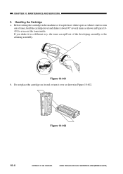
... its end or turn it in a different way, the toner can spill out of toner, hold the cartridge level and shake it about 90° several times as shown in Figure 10-402. If you shake it over as shown in the machine ... spots as when it starts to even out the toner inside. Figure 10-401 b. Before setting the cartridge in Figure 10401 to run out of the developing assembly or the cleaning assembly. Handling the Cartridge a. CANON PC800s/900s REV.0 AUG. 1999 PRINTED IN JAPAN (IMPRIME AU JAPON) Figure 10-402 10-4 COPYRIGHT ©...
... its end or turn it in a different way, the toner can spill out of toner, hold the cartridge level and shake it about 90° several times as shown in Figure 10-402. If you shake it over as shown in the machine ... spots as when it starts to even out the toner inside. Figure 10-401 b. Before setting the cartridge in Figure 10401 to run out of the developing assembly or the cleaning assembly. Handling the Cartridge a. CANON PC800s/900s REV.0 AUG. 1999 PRINTED IN JAPAN (IMPRIME AU JAPON) Figure 10-402 10-4 COPYRIGHT ©...
Service Manual
Page 262
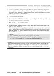
...of children. Reference: If the photosensitive drum is provided as 10000 and 30000 lux.) COPYRIGHT © 1999 CANON INC. Do not subject the cartridge to work briskly when removing a jam or replacing the cartridge. 2. Try leaving the machine alone as long as by opening the shutter for 5 min, it should ...not leave it . e. In particular, do not impose force on the shutter for 5 min and then left alone in mind: Caution: 1. If the cartridge must be taken out of the machine for storage, be sure to light of white spots or vertical bands), however, may not disappear. CHAPTER 10...
...of children. Reference: If the photosensitive drum is provided as 10000 and 30000 lux.) COPYRIGHT © 1999 CANON INC. Do not subject the cartridge to work briskly when removing a jam or replacing the cartridge. 2. Try leaving the machine alone as long as by opening the shutter for 5 min, it should ...not leave it . e. In particular, do not impose force on the shutter for 5 min and then left alone in mind: Caution: 1. If the cartridge must be taken out of the machine for storage, be sure to light of white spots or vertical bands), however, may not disappear. CHAPTER 10...
Service Manual
Page 268
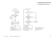
...if the machine is not equipped with a copy density correction switch (SW101). 2. Check the following : 1. COPYRIGHT © 1999 CANON INC. Presence/absence of background (Note 2) I. See p. 11-42. Composite power supply PCB (See the appropriate troubleshooting procedure.)... Note 2) 4. See the appropriate troubleshooting procedure. 3. MAINTENANCE AND INSPECTION A. Scanning lamp 3. AE sensor PCB 4. CANON PC800s/900s REV.0 AUG. 1999 PRINTED IN JAPAN (IMPRIME AU JAPON) 11-3 NO YES Can the deviation be...of difference between front and rear (Note 2) 3. Cartridge 2.
...if the machine is not equipped with a copy density correction switch (SW101). 2. Check the following : 1. COPYRIGHT © 1999 CANON INC. Presence/absence of background (Note 2) I. See p. 11-42. Composite power supply PCB (See the appropriate troubleshooting procedure.)... Note 2) 4. See the appropriate troubleshooting procedure. 3. MAINTENANCE AND INSPECTION A. Scanning lamp 3. AE sensor PCB 4. CANON PC800s/900s REV.0 AUG. 1999 PRINTED IN JAPAN (IMPRIME AU JAPON) 11-3 NO YES Can the deviation be...of difference between front and rear (Note 2) 3. Cartridge 2.
Service Manual
Page 269
... Item Tools/solvents Work/remarks Single-feeder pickup roller Moist cloth or alcohol Cleaning. Cleaning. Cleaning. Cleaning. 11-4 Cartridge Item Drum cover shutter Tools/solvents Most cloth Work/remarks Cleaning; Take care not to Note for Servicing Copyboard, Scanner...No. 6 mirror Tools/solvent Alcohol Alcohol Blower brush Lint-free paper Blower brush Work/remarks Cleaning. Cleaning. COPYRIGHT © 1999 CANON INC. Do not use water or solvent. B. Cleaning. Cleaning. Multifeeder, Pickup roller Moist cloth or alcohol Cleaning. Points to ...
... Item Tools/solvents Work/remarks Single-feeder pickup roller Moist cloth or alcohol Cleaning. Cleaning. Cleaning. Cleaning. 11-4 Cartridge Item Drum cover shutter Tools/solvents Most cloth Work/remarks Cleaning; Take care not to Note for Servicing Copyboard, Scanner...No. 6 mirror Tools/solvent Alcohol Alcohol Blower brush Lint-free paper Blower brush Work/remarks Cleaning. Cleaning. COPYRIGHT © 1999 CANON INC. Do not use water or solvent. B. Cleaning. Cleaning. Multifeeder, Pickup roller Moist cloth or alcohol Cleaning. Points to ...

Service Manual
Page 307
...adjustment, you have replaced any of VR107 Clockwise Counterclockwise Copy density Lighter Darker Table 11-207 11-42 COPYRIGHT © 1999 CANON INC. Making Adjustments 1) Set a cartridge in the machine. 2) Set the density correction switch (SW101) to its middle index. 4) Place the Test Sheet on the... copyboard, and make a copy. 5) Turn VR107 on the control panel to its middle index. CANON PC800s/900s REV.0 AUG. 1999 PRINTED IN...
...adjustment, you have replaced any of VR107 Clockwise Counterclockwise Copy density Lighter Darker Table 11-207 11-42 COPYRIGHT © 1999 CANON INC. Making Adjustments 1) Set a cartridge in the machine. 2) Set the density correction switch (SW101) to its middle index. 4) Place the Test Sheet on the... copyboard, and make a copy. 5) Turn VR107 on the control panel to its middle index. CANON PC800s/900s REV.0 AUG. 1999 PRINTED IN...


