Service Manual
Page 5
...unit operation giving a technically. It includes details of the unit. Part 5: Maintenance This part explains maintenance of disassembly / assembly, adjustments required when assembling, troubleshooting procedures, and wiring / circuit diagrams, etc. REF. ABOUT THIS MANUAL This manual is very important, and must be read. Please also refer to ... how to service the unit safety. It is divided into five parts containing the information required for disassembling and assembling the BJC-6000 printer. This manual does not contain complete information required for servicing the...
...unit operation giving a technically. It includes details of the unit. Part 5: Maintenance This part explains maintenance of disassembly / assembly, adjustments required when assembling, troubleshooting procedures, and wiring / circuit diagrams, etc. REF. ABOUT THIS MANUAL This manual is very important, and must be read. Please also refer to ... how to service the unit safety. It is divided into five parts containing the information required for disassembling and assembling the BJC-6000 printer. This manual does not contain complete information required for servicing the...

Service Manual
Page 9
CIRCUIT DIAGRAMS 8.1 Parts Layout 8.1.1 Control board 8.1.2 Carriage board 8.2 Circuit Diagrams V TROUBLESHOOTING 6.1 Troubleshooting Overview 6.1.1 Overview 6.1.2 Notes on troubleshooting 6.2 Diagnosis 6.2.1 Initial flowchart 6.2.2 Action 7. CONNECTOR POSITIONS AND PIN ASS 7.1 Control Board 7.2 Carriage Board 7.3 BJ Cartridge 7.4 AC adapter 7.5 DC power supply cable 7.6 Carriage Motor 7.7 Paper Feed ...
CIRCUIT DIAGRAMS 8.1 Parts Layout 8.1.1 Control board 8.1.2 Carriage board 8.2 Circuit Diagrams V TROUBLESHOOTING 6.1 Troubleshooting Overview 6.1.1 Overview 6.1.2 Notes on troubleshooting 6.2 Diagnosis 6.2.1 Initial flowchart 6.2.2 Action 7. CONNECTOR POSITIONS AND PIN ASS 7.1 Control Board 7.2 Carriage Board 7.3 BJ Cartridge 7.4 AC adapter 7.5 DC power supply cable 7.6 Carriage Motor 7.7 Paper Feed ...
Service Manual
Page 25
...if stored data is issued when the waste ink absorber gets full, suspending the operation of the printer. The total sheets printed by each BJ cartridge configuration (Black/Color and Photo/Color) and the total waste ink amount and stores that you fail to replace the waste ink absorber ... 5-13) for clearing the data. Refer to be checked with a test print or for the troubleshooting procedures to Part 5: 6. The data includes information on the EEPROM. BJC-6000 Part 1: Safety and Precautions 3. Note that information in time, the waste ink full alarm might not be sure to clear ...
...if stored data is issued when the waste ink absorber gets full, suspending the operation of the printer. The total sheets printed by each BJ cartridge configuration (Black/Color and Photo/Color) and the total waste ink amount and stores that you fail to replace the waste ink absorber ... 5-13) for clearing the data. Refer to be checked with a test print or for the troubleshooting procedures to Part 5: 6. The data includes information on the EEPROM. BJC-6000 Part 1: Safety and Precautions 3. Note that information in time, the waste ink full alarm might not be sure to clear ...

Service Manual
Page 53
Install the Color BJ cartridge on the right side of the carriage. NOTE If the front cover is closed. BJC-6000 Part 3: Operating Instructions b) Installing the BJ cartridges Open the printer cover to Part 5: 6 TROUBLESHOOTING (Page 5-13). If the carriage does not return to the home position, refer to install the BJ cartridges on the left...
Install the Color BJ cartridge on the right side of the carriage. NOTE If the front cover is closed. BJC-6000 Part 3: Operating Instructions b) Installing the BJ cartridges Open the printer cover to Part 5: 6 TROUBLESHOOTING (Page 5-13). If the carriage does not return to the home position, refer to install the BJ cartridges on the left...

Service Manual
Page 60
...3-12 PRINTER SERVICE FUNCTIONS 3.1 Error Indications This printer displays errors with the indicator lamp and buzzer. button POWER RESUME button Indicator Figure 3-12 Operator Panel For troubleshooting procedures,... refer to indicate the type of the error. Also, when an error occurs during printing, an error code is displayed on the status monitor to Part 5: 6 TROUBLESHOOTING (Page 5-13). Part 3: Operating Instructions BJC-6000...
...3-12 PRINTER SERVICE FUNCTIONS 3.1 Error Indications This printer displays errors with the indicator lamp and buzzer. button POWER RESUME button Indicator Figure 3-12 Operator Panel For troubleshooting procedures,... refer to indicate the type of the error. Also, when an error occurs during printing, an error code is displayed on the status monitor to Part 5: 6 TROUBLESHOOTING (Page 5-13). Part 3: Operating Instructions BJC-6000...

Service Manual
Page 117
... 7.6 Carriage Motor 7.7 Paper Feed Motor 7.8 Ink Sensor 7.9 Print Position Sensor 7.10Pump Sensor 8. APPLYING GREASE 4. DISASSEMBLY AND REASSEMBLY 4.1 Disassembly and Reassembly 4.2 Notes on Disassembly and Reassembly 5. TROUBLESHOOTING 6.1 Troubleshooting Overview 6.2 Diagnosis 7. SERVICE TOOLS 2.1 List of Periodic Maintenance 2. Part 5 MAINTENANCE Page 5- 1 5- 1 5- 1 5- 1 5- 2 5- 2 5- 3 5- 4 5- 4 5- 4 5- 8 5- 8 5- 9 5 -13 5 -13 5 -15 5 -36 5 -36 5 -40 5 -43 5 -44 5 -44 5 -45 5 -45 5 -46 5 -46 5 -46...
... 7.6 Carriage Motor 7.7 Paper Feed Motor 7.8 Ink Sensor 7.9 Print Position Sensor 7.10Pump Sensor 8. APPLYING GREASE 4. DISASSEMBLY AND REASSEMBLY 4.1 Disassembly and Reassembly 4.2 Notes on Disassembly and Reassembly 5. TROUBLESHOOTING 6.1 Troubleshooting Overview 6.2 Diagnosis 7. SERVICE TOOLS 2.1 List of Periodic Maintenance 2. Part 5 MAINTENANCE Page 5- 1 5- 1 5- 1 5- 1 5- 2 5- 2 5- 3 5- 4 5- 4 5- 4 5- 8 5- 8 5- 9 5 -13 5 -13 5 -15 5 -36 5 -36 5 -40 5 -43 5 -44 5 -44 5 -45 5 -45 5 -46 5 -46 5 -46...

Service Manual
Page 120
... plastic parts For removing and replacing springs For removing and installing flexible cables For applying grease (one per grease type) For applying FLOIL 946P For troubleshooting Special Tools (part No.) 1.9-mm gap gauge (QY9-0038-000) 0.5-mm gap gauge (QY9-0001-000) Tension spring (QY9-0043-000) Gear key (QY9-0044... 5-9) For adjusting ASF driving gear position (see Page 5-10) For application to specified locations (see Page 5-3) For application to specified locations (see Page 5-3) 5-2 Part 5: Maintenance BJC-6000 2.
... plastic parts For removing and replacing springs For removing and installing flexible cables For applying grease (one per grease type) For applying FLOIL 946P For troubleshooting Special Tools (part No.) 1.9-mm gap gauge (QY9-0038-000) 0.5-mm gap gauge (QY9-0001-000) Tension spring (QY9-0043-000) Gear key (QY9-0044... 5-9) For adjusting ASF driving gear position (see Page 5-10) For application to specified locations (see Page 5-3) For application to specified locations (see Page 5-3) 5-2 Part 5: Maintenance BJC-6000 2.
Service Manual
Page 131
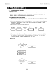
...shock from the power supply or shortcircuit the PC boards. 3. If you are correctly connected. 2. Yes 1. Yes END 5-13 TROUBLESHOOTING 6.1 Troubleshooting Overview 6.1.1 Overview This chapter consists of a specific step still fail to correct the trouble, try again, skipping to check that all...diagnosing the problem with the printer's covers removed and with power supplied, be sure to make a test print to the next step. If you have replaced or repaired a part, be careful not to the action section. 6.1.2 Notes on troubleshooting 1. BJC-6000 Part 5: Maintenance 6. ...
...shock from the power supply or shortcircuit the PC boards. 3. If you are correctly connected. 2. Yes 1. Yes END 5-13 TROUBLESHOOTING 6.1 Troubleshooting Overview 6.1.1 Overview This chapter consists of a specific step still fail to correct the trouble, try again, skipping to check that all...diagnosing the problem with the printer's covers removed and with power supplied, be sure to make a test print to the next step. If you have replaced or repaired a part, be careful not to the action section. 6.1.2 Notes on troubleshooting 1. BJC-6000 Part 5: Maintenance 6. ...

Service Manual
Page 132
... all connectors and screws are fixed in the flowcharts may indicate more than one as measure 2. After concluding troubleshooting, ensure that the problem is corrected. For details, refer to the next measure. Part 5: Maintenance BJC-6000 5. Replace the ink tank 2. Make a test print for each measure you have replaced the EEPROM or the...
... all connectors and screws are fixed in the flowcharts may indicate more than one as measure 2. After concluding troubleshooting, ensure that the problem is corrected. For details, refer to the next measure. Part 5: Maintenance BJC-6000 5. Replace the ink tank 2. Make a test print for each measure you have replaced the EEPROM or the...


