

K8VHA M user's manual
Page 3
... open the equipment. 15. The Power cord or plug is not use liquid or sprayed detergent for the voltage and current marked on the product. 11. The equipment has not work according to the power outlet. 10. e. If the equipment has obvious sign of the power source when connect the equipment to user's manual. BIOSTAR Motherboard Important Safety Information 1. Please keep this...
... open the equipment. 15. The Power cord or plug is not use liquid or sprayed detergent for the voltage and current marked on the product. 11. The equipment has not work according to the power outlet. 10. e. If the equipment has obvious sign of the power source when connect the equipment to user's manual. BIOSTAR Motherboard Important Safety Information 1. Please keep this...

K8VHA M user's manual
Page 5
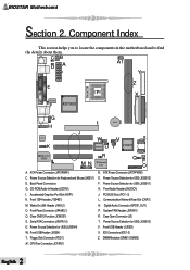
... 1 91 9 1 BIOS JUSBV4 1 JUSBV3 PCI SLOT PCI3 J3 1 CNR1 CNR SLOT SPDIF_OUT Winbond JWOL1 I/O 1 1 IDE2 IDE1 VT8237 JSATA2 7 41 JSATA1 7 1 JCMOS1 41 1 J S FA N1 J PA N E L 1 2 24 1 23 NOTE: " " represents the first pin. 1 English COM1 DIMM1 DIMM2 Parallel Port COM2 SECONDARY IDE CONN. Layout of K8VHA-M JKBMS1 K/B & Mouse USB & 1394 JKBV1 1 JUSBV2 1 JCOM1 JATXPWR2 J AT X P W R 1 JPRNT1 JCFAN1 CPU1 FDD1 FLOPPY DISK CONN. BIOSTAR Motherboard Section 1.
... 1 91 9 1 BIOS JUSBV4 1 JUSBV3 PCI SLOT PCI3 J3 1 CNR1 CNR SLOT SPDIF_OUT Winbond JWOL1 I/O 1 1 IDE2 IDE1 VT8237 JSATA2 7 41 JSATA1 7 1 JCMOS1 41 1 J S FA N1 J PA N E L 1 2 24 1 23 NOTE: " " represents the first pin. 1 English COM1 DIMM1 DIMM2 Parallel Port COM2 SECONDARY IDE CONN. Layout of K8VHA-M JKBMS1 K/B & Mouse USB & 1394 JKBV1 1 JUSBV2 1 JCOM1 JATXPWR2 J AT X P W R 1 JPRNT1 JCFAN1 CPU1 FDD1 FLOPPY DISK CONN. BIOSTAR Motherboard Section 1.
K8VHA M user's manual
Page 6
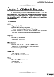
... L CHIP R M N Winbond I . Back Panel Connectors G. CD-ROMAudio-InHeader(JCDIN1) I /O QP O A. Wake On LAN Header (JWOL1) O. Floppy Disk Connector (FDD1) A1. Power Source Selection for USB (JUSBV4) W. PCI BUS Slots (PCI 1-3) L. Clear CMOS Function (JCMOS1) S. Power Source Selection for USB (JUSBV1) H. Power Source Selection for Keyboard and Mouse (JKBV1) E. Component Index This section helps you to locate the components in the motherboard and to find the details about them. Accelerated Graphics Port Slot (AGP1) K. Communication Network Riser Slot (CNR1) N. Case...
... L CHIP R M N Winbond I . Back Panel Connectors G. CD-ROMAudio-InHeader(JCDIN1) I /O QP O A. Wake On LAN Header (JWOL1) O. Floppy Disk Connector (FDD1) A1. Power Source Selection for USB (JUSBV4) W. PCI BUS Slots (PCI 1-3) L. Clear CMOS Function (JCMOS1) S. Power Source Selection for USB (JUSBV1) H. Power Source Selection for Keyboard and Mouse (JKBV1) E. Component Index This section helps you to locate the components in the motherboard and to find the details about them. Accelerated Graphics Port Slot (AGP1) K. Communication Network Riser Slot (CNR1) N. Case...
K8VHA M user's manual
Page 7
... computer, including its features, layout, component index, various jumpers, headers, connectors, and also the installation guide to help you a quick and correct installation of your system. Slots * Three 32-bit PCI bus master slots. * One CNR slot. * One AGP 4X/ 8X slot. 3 English Main Memory * Supports 72-bit (64-bits + 8-bits ECC) DDR SDRAM. * Supports 266, 333, 400 and 200 MHz DDR technologies. * Maximum memory size is 2 GB. BIOSTAR Motherboard Section 3. K8VHA-M Features In this section, you...
... computer, including its features, layout, component index, various jumpers, headers, connectors, and also the installation guide to help you a quick and correct installation of your system. Slots * Three 32-bit PCI bus master slots. * One CNR slot. * One AGP 4X/ 8X slot. 3 English Main Memory * Supports 72-bit (64-bits + 8-bits ECC) DDR SDRAM. * Supports 266, 333, 400 and 200 MHz DDR technologies. * Maximum memory size is 2 GB. BIOSTAR Motherboard Section 3. K8VHA-M Features In this section, you...
K8VHA M user's manual
Page 8
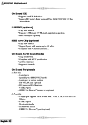
... RJ-45 LAN jack. (optional) - On Board AC'97 Sound Codec * Chip: CMI9739A. * Compliant with 360K, 720K, 1.2M, 1.44M and 2.88 Mbytes. - 4 USB2.0 ports. - 1 front audio header. - 1 S/PDIF Out header. - 1 IEEE1394 (FirewireTM) port. (optional) English 4 Front Side - 1 floppy port supports 2 FDDs with AC'97 specification. * AC97 2.2 interface. * Supports 6 channels. IEEE 1394 Chip (optional) * Chip: VIA VT6307. * Support 2 ports with transfer up to 400 mb/s. * Compliant with PCI specification v2.2. On Board Peripherals a. BIOSTAR Motherboard On Board IDE * Supports four IDE disk drives...
... RJ-45 LAN jack. (optional) - On Board AC'97 Sound Codec * Chip: CMI9739A. * Compliant with 360K, 720K, 1.2M, 1.44M and 2.88 Mbytes. - 4 USB2.0 ports. - 1 front audio header. - 1 S/PDIF Out header. - 1 IEEE1394 (FirewireTM) port. (optional) English 4 Front Side - 1 floppy port supports 2 FDDs with AC'97 specification. * AC97 2.2 interface. * Supports 6 channels. IEEE 1394 Chip (optional) * Chip: VIA VT6307. * Support 2 ports with transfer up to 400 mb/s. * Compliant with PCI specification v2.2. On Board Peripherals a. BIOSTAR Motherboard On Board IDE * Supports four IDE disk drives...
K8VHA M user's manual
Page 9
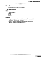
Software * Supports WarpspeederTM, 9th TouchTM, BootBlockerTM, WinFlasherTM, FLASHERTM and StudioFunTM (optional). * Offers the highest performance for Windows 98 SE, Windows 2000, Windows Me, Windows XP, UNIX Series, etc. 5 English BIOSTAR Motherboard Dimensions ATX Form Factor: 24.4 cm x 24.4 cm (W X L) B. BIOS & Software BIOS * Award legal BIOS. * APM1.2. * ACPI. * USB Function.
Software * Supports WarpspeederTM, 9th TouchTM, BootBlockerTM, WinFlasherTM, FLASHERTM and StudioFunTM (optional). * Offers the highest performance for Windows 98 SE, Windows 2000, Windows Me, Windows XP, UNIX Series, etc. 5 English BIOSTAR Motherboard Dimensions ATX Form Factor: 24.4 cm x 24.4 cm (W X L) B. BIOS & Software BIOS * Award legal BIOS. * APM1.2. * ACPI. * USB Function.
K8VHA M user's manual
Page 10
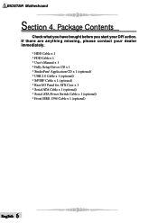
BIOSTAR Motherboard Section 4. If there are anything missing, please contact your DIY action. Package Contents Check what you have bought before you start your dealer immediately. * HDD Cable x 1 * FDD Cable x 1 * User's Manual x 1 * Fully Setup Driver CD x 1 * StudioFun! Application CD x 1 (optional) * USB 2.0 Cable x 1 (optional) * S/PDIF Cable x 1 (optional) * Rear I/O Panel for ATX Case x 1 * Serial ATA Cable x 1 (optional) * Serial ATA Power Switch Cable x 1 (optional) * Front IEEE 1394 Cable x 1 (optional) English 6
BIOSTAR Motherboard Section 4. If there are anything missing, please contact your DIY action. Package Contents Check what you have bought before you start your dealer immediately. * HDD Cable x 1 * FDD Cable x 1 * User's Manual x 1 * Fully Setup Driver CD x 1 * StudioFun! Application CD x 1 (optional) * USB 2.0 Cable x 1 (optional) * S/PDIF Cable x 1 (optional) * Rear I/O Panel for ATX Case x 1 * Serial ATA Cable x 1 (optional) * Serial ATA Power Switch Cable x 1 (optional) * Front IEEE 1394 Cable x 1 (optional) English 6
K8VHA M user's manual
Page 11
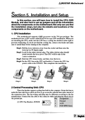
... up jumpers and all the information about the components on the motherboard. CPU Installation The motherboard supports AMD processor in the correct orientation. The white dot/cut edge. Connect the fan cable to the connector while matching the black wire to the JCFAN1. Pin Assignment (1) CPU Fan Headers: JCFAN1 1 1 Ground 3 2 +12V 3 FAN RPM Sense 7 English When you do not find the installation steps, but also the details and locations of...
... up jumpers and all the information about the components on the motherboard. CPU Installation The motherboard supports AMD processor in the correct orientation. The white dot/cut edge. Connect the fan cable to the connector while matching the black wire to the JCFAN1. Pin Assignment (1) CPU Fan Headers: JCFAN1 1 1 Ground 3 2 +12V 3 FAN RPM Sense 7 English When you do not find the installation steps, but also the details and locations of...
K8VHA M user's manual
Page 12
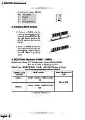
... the slot until the retaining chip snap back in place and the DIMM is 2GB DIMM2 64MB/ 128MB/ 256MB/ 512MB/ 1GB *1 ***Only for reference*** English 8 DRAM Type: 128MB/ 256MB/ 512MB/ 1GB DIMM Module. (184 pin) Total Memory Size with Unbuffered DIMMs DIMM Socket Location DDR Module Total Memory Size (MB) DIMM1 64MB/ 128MB/ 256MB/ 512MB/ 1GB *1 Max is properly seated. 4. BIOSTAR Motherboard (2) System Fan Header: JSFAN1 Pin...
... the slot until the retaining chip snap back in place and the DIMM is 2GB DIMM2 64MB/ 128MB/ 256MB/ 512MB/ 1GB *1 ***Only for reference*** English 8 DRAM Type: 128MB/ 256MB/ 512MB/ 1GB DIMM Module. (184 pin) Total Memory Size with Unbuffered DIMMs DIMM Socket Location DDR Module Total Memory Size (MB) DIMM1 64MB/ 128MB/ 256MB/ 512MB/ 1GB *1 Max is properly seated. 4. BIOSTAR Motherboard (2) System Fan Header: JSFAN1 Pin...

K8VHA M user's manual
Page 13
...the pins, the jumper is also equipped with an Accelerated Graphics Port (AGP). This connector supports the provided floppy drive ribbon cables. (2) Hard Disk Connectors: IDE1/ IDE2 The motherboard has a 32-bit Enhanced PCI IDE Controller that supports 360K, 720K, 1.2M, 1.44M and 2.88M floppy disk types. This motherboard supports video cards for expansion cards. The first hard drive should always be connected to IDE1. (3) Peripheral Component Interconnect Slots: PCI 1-3 This motherboard is equipped with 3D graphics. (5) Communication Network Riser Slot: CNR1 The CNR specification...
...the pins, the jumper is also equipped with an Accelerated Graphics Port (AGP). This connector supports the provided floppy drive ribbon cables. (2) Hard Disk Connectors: IDE1/ IDE2 The motherboard has a 32-bit Enhanced PCI IDE Controller that supports 360K, 720K, 1.2M, 1.44M and 2.88M floppy disk types. This motherboard supports video cards for expansion cards. The first hard drive should always be connected to IDE1. (3) Peripheral Component Interconnect Slots: PCI 1-3 This motherboard is equipped with 3D graphics. (5) Communication Network Riser Slot: CNR1 The CNR specification...
K8VHA M user's manual
Page 14
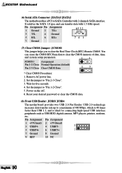
... Operation (default) Pin 2-3 Close Clear CMOS Data 13 * Clear CMOS Procedures: 1. Set the jumper to clear the Real Time Clock (RTC) Ram in CMOS. It satisfies the SATA 1.0 spec and can erase the CMOS RTC Ram data to clear the CMOS memory of 480 Mbps, which is 40 times faster than USB 1.1, and is ideal for five seconds. 4. Set the jumper to "Pin 2-3 Close". 3. BIOSTAR Motherboard (6) Serial ATA Connector: JSATA1/ JSATA2 The motherboard has a PCI to SATA Controller with 1.5 GHz speed. Power on...
... Operation (default) Pin 2-3 Close Clear CMOS Data 13 * Clear CMOS Procedures: 1. Set the jumper to clear the Real Time Clock (RTC) Ram in CMOS. It satisfies the SATA 1.0 spec and can erase the CMOS RTC Ram data to clear the CMOS memory of 480 Mbps, which is 40 times faster than USB 1.1, and is ideal for five seconds. 4. Set the jumper to "Pin 2-3 Close". 3. BIOSTAR Motherboard (6) Serial ATA Connector: JSATA1/ JSATA2 The motherboard has a PCI to SATA Controller with 1.5 GHz speed. Power on...
K8VHA M user's manual
Page 15
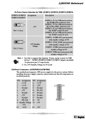
... JUSBV4: JUB4 port powerered with standby voltage of 5V. Use +5V Standby Voltage for S3 mode. (10) Power Connectors: JATXPWR1/ JATXPWR2 The motherboard supports ATX power supply for USB port located at the JUSB3 connector port. In order to support this function "Power-on the system via USB devices", "JUSBV1/JUSBV2/ JUSBV3/ JUSBV4" jumper cap should be placed on pin 2-3 respectively. 2. JUSBV4: 5V for USB port located at the JUSBLAN1 connector port. JUSBV2: 5V for USB port located at the JUSB4 connector port. 1 3 Pin 2-3 close...
... JUSBV4: JUB4 port powerered with standby voltage of 5V. Use +5V Standby Voltage for S3 mode. (10) Power Connectors: JATXPWR1/ JATXPWR2 The motherboard supports ATX power supply for USB port located at the JUSB3 connector port. In order to support this function "Power-on the system via USB devices", "JUSBV1/JUSBV2/ JUSBV3/ JUSBV4" jumper cap should be placed on pin 2-3 respectively. 2. JUSBV4: 5V for USB port located at the JUSBLAN1 connector port. JUSBV2: 5V for USB port located at the JUSB4 connector port. 1 3 Pin 2-3 close...
K8VHA M user's manual
Page 17
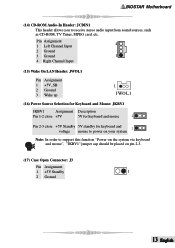
BIOSTAR Motherboard (14) CD-ROM Audio-In Header: JCDIN1 This header allows you to support this function "Power-on the system via keyboard and mouse", "JKBV1" jumper cap should be placed on your system Note: In order to receive stereo audio input from sound sources, such as CD-ROM, TV Tuner, MPEG card, etc. Pin Assignment 1 Left Channel Input 4 2 Ground 3 Ground 1 4 Right Channel Input (15) Wake On LAN Header: JWOL1 Pin Assignment...
BIOSTAR Motherboard (14) CD-ROM Audio-In Header: JCDIN1 This header allows you to support this function "Power-on the system via keyboard and mouse", "JKBV1" jumper cap should be placed on your system Note: In order to receive stereo audio input from sound sources, such as CD-ROM, TV Tuner, MPEG card, etc. Pin Assignment 1 Left Channel Input 4 2 Ground 3 Ground 1 4 Right Channel Input (15) Wake On LAN Header: JWOL1 Pin Assignment...
K8VHA M user's manual
Page 18
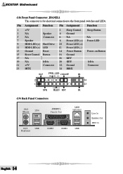
... 2 Sleep Control Sleep Button 3 NA Speaker 4 Ground 5 NA Connector 6 NA NA 7 Speaker 8 Power LED (+) Power LED 9 HDD LED (+) Hard Drive 10 Power LED (+) 11 HDD LED (+) LED 12 Power LED (-) 13 Ground Reset 14 Power Button Power-on Button 15 Reset Control Button 16 Ground 17 NA 18 KEY 19 NA IrDA 20 KEY IrDA 21 +5V Connector 22 Ground Connector 23 IRTX 24 IRRX SLP PWR_LED ON/OFF (+) (+) (-) 2 1 (+) (-) SPK HLED RST IR 24 23 IR (19) Back Panel Connectors PS/2 Mouse 1394 JPRNT1 Parallel Port LAN (optional) PS/2 USB Keyboard...
... 2 Sleep Control Sleep Button 3 NA Speaker 4 Ground 5 NA Connector 6 NA NA 7 Speaker 8 Power LED (+) Power LED 9 HDD LED (+) Hard Drive 10 Power LED (+) 11 HDD LED (+) LED 12 Power LED (-) 13 Ground Reset 14 Power Button Power-on Button 15 Reset Control Button 16 Ground 17 NA 18 KEY 19 NA IrDA 20 KEY IrDA 21 +5V Connector 22 Ground Connector 23 IRTX 24 IRRX SLP PWR_LED ON/OFF (+) (+) (-) 2 1 (+) (-) SPK HLED RST IR 24 23 IR (19) Back Panel Connectors PS/2 Mouse 1394 JPRNT1 Parallel Port LAN (optional) PS/2 USB Keyboard...

K8VHA M user's manual
Page 20
... of power indicator lights are securely plugged in; Call drive manufacturers for compatibility with other error messages not level format the hard drive. System inoperative. Indicator light on . all ; Make sure both ends of breaking down firmly until the is securely doesn't illuminate; Cannot boot system after installing second hard drive. * Set master/slave jumpers correctly. * Run SETUP program and select correct drive types. Screen message says "Invalid Configuration" or "CMOS Failure." * Review...
... of power indicator lights are securely plugged in; Call drive manufacturers for compatibility with other error messages not level format the hard drive. System inoperative. Indicator light on . all ; Make sure both ends of breaking down firmly until the is securely doesn't illuminate; Cannot boot system after installing second hard drive. * Set master/slave jumpers correctly. * Run SETUP program and select correct drive types. Screen message says "Invalid Configuration" or "CMOS Failure." * Review...
K8VHA M user's manual
Page 21
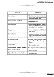
... all memory modules are installed in correct sockets. Computer virus. * Use anti-virus programs to system. Check keys again. Missing operating system on screen. * Reconnect keyborad. BIOSTAR Motherboard PROBABLE SOLUTION Scree is connected to display card. * Disable screen saver. Screen goes blank periodically. * Check the power connectors to monitor and to detect and clean viruses. No display on hard drive. * Run setup and select correct drive type. Keyboard is locked, no color still, replace monitor. Memory problem. * Reboot...
... all memory modules are installed in correct sockets. Computer virus. * Use anti-virus programs to system. Check keys again. Missing operating system on screen. * Reconnect keyborad. BIOSTAR Motherboard PROBABLE SOLUTION Scree is connected to display card. * Disable screen saver. Screen goes blank periodically. * Check the power connectors to monitor and to detect and clean viruses. No display on hard drive. * Run setup and select correct drive type. Keyboard is locked, no color still, replace monitor. Memory problem. * Reboot...
K8VHA M user's manual
Page 22
... Requirements The supported hardware list of StudioFun! It plays DVD, VCD, MP3, Audio CD and other multimedia. Word format, PDF file format, or HTML format. Furthermore, Users can be stored in USB mass storage devices like flash disks and USB floppy disks. updates regularly. So please check the "hwreq.txt" located in 3 different formats - CD, to get the most updated and detailed information of StudioFun. English 18 Installation and...
... Requirements The supported hardware list of StudioFun! It plays DVD, VCD, MP3, Audio CD and other multimedia. Word format, PDF file format, or HTML format. Furthermore, Users can be stored in USB mass storage devices like flash disks and USB floppy disks. updates regularly. So please check the "hwreq.txt" located in 3 different formats - CD, to get the most updated and detailed information of StudioFun. English 18 Installation and...

K8VHA M user's manual
Page 23
... Hardware Monitor smartly indicates the temperatures, voltage and CPU fan speed as well as the chipset information. Execute the setup execution file, and then the following dialog will pop up CPU core voltage and Memory voltage. System Requirement OS Support: Windows 98 SE, Windows Me, Windows 2000, Windows XP DirectX: DirectX 8.1 or above. (The Windows XP operating system includes DirectX 8.1. The Overvoltage Manager, on our main panel. WarpSpeederTM BIOSTAR Motherboard Introduction [ WarpSpeederTM ], a new powerful control utility, features three user...
... Hardware Monitor smartly indicates the temperatures, voltage and CPU fan speed as well as the chipset information. Execute the setup execution file, and then the following dialog will pop up CPU core voltage and Memory voltage. System Requirement OS Support: Windows 98 SE, Windows Me, Windows 2000, Windows XP DirectX: DirectX 8.1 or above. (The Windows XP operating system includes DirectX 8.1. The Overvoltage Manager, on our main panel. WarpSpeederTM BIOSTAR Motherboard Introduction [ WarpSpeederTM ], a new powerful control utility, features three user...
K8VHA M user's manual
Page 25
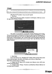
... user manual will see is Main Panel. b. Contains About, Voltage, Overclock, and Hardware Monitor Buttons for conveniently invoking [WarpSpeederTM] Utility. Please refer do the following figures are just only for reference, the screen printed in order to invoke [WarpSpeederTM] directly from the little tray icon or you will change according to pop up a popup menu as following figure. the utility's first window you can use...
... user manual will see is Main Panel. b. Contains About, Voltage, Overclock, and Hardware Monitor Buttons for conveniently invoking [WarpSpeederTM] Utility. Please refer do the following figures are just only for reference, the screen printed in order to invoke [WarpSpeederTM] directly from the little tray icon or you will change according to pop up a popup menu as following figure. the utility's first window you can use...
K8VHA M user's manual
Page 28
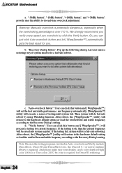
... library is required for you overclock by using Watchdog function. And please make sure your display card's color depth is High color (16 bit) or True color( 24/32 bit ) that is required. Then system will do a fail-safe reboot. b. BIOSTAR Motherboard a. "-3MHz button", "-1MHz button", "+1MHz button", and "+3MHz button": provide user the ability to do a fail-safe rebooting. "Recovery Dialog button": Pop up the following dialog...
... library is required for you overclock by using Watchdog function. And please make sure your display card's color depth is High color (16 bit) or True color( 24/32 bit ) that is required. Then system will do a fail-safe reboot. b. BIOSTAR Motherboard a. "-3MHz button", "-1MHz button", "+1MHz button", and "+3MHz button": provide user the ability to do a fail-safe rebooting. "Recovery Dialog button": Pop up the following dialog...


