
K8VHA M user's manual
Page 1
D. CE Mark This equipment is no guarantee that to which can be shielded. BIOSTAR Motherboard FCC Statement This equipment has been tested and found to comply with the EMC directive. C. i English Any changes or modification made to this equipment void ...
D. CE Mark This equipment is no guarantee that to which can be shielded. BIOSTAR Motherboard FCC Statement This equipment has been tested and found to comply with the EMC directive. C. i English Any changes or modification made to this equipment void ...
K8VHA M user's manual
Page 2
... be construed as a commitment by the manufacturer. Intel and Pentium are registered trademarks of Silicon Integrated Systems Corporation. Sis is registered trademark of Intel Corporation. BIOSTAR Motherboard Overview The information in this document is subject to change without the prior written permission of the manufacturer. No responsibility is registered trademark of Nvidia...
... be construed as a commitment by the manufacturer. Intel and Pentium are registered trademarks of Silicon Integrated Systems Corporation. Sis is registered trademark of Intel Corporation. BIOSTAR Motherboard Overview The information in this document is subject to change without the prior written permission of the manufacturer. No responsibility is registered trademark of Nvidia...

K8VHA M user's manual
Page 3
..., this User's Manual for air convection hence protect the equipment from mains to the power outlet. 10. The equipment has not work according to moisture. BIOSTAR Motherboard Important Safety Information 1. Please keep this equipment from humidity. 6. Please keep this could cause injury. 7. Lay this equipment in an environment unconditioned, storage temperature above...
..., this User's Manual for air convection hence protect the equipment from mains to the power outlet. 10. The equipment has not work according to moisture. BIOSTAR Motherboard Important Safety Information 1. Please keep this equipment from humidity. 6. Please keep this could cause injury. 7. Lay this equipment in an environment unconditioned, storage temperature above...
K8VHA M user's manual
Page 4
Layout of Contents iv Section 1. Package Contents 6 Section 5. Installation and Setup 7 Section 6. K8VHA-M Features 3 Section 4. Trouble Shooting 16 StudioFun!TM 18 WarpSpeederTM 19 English iv Component Index 2 Section 3. BIOSTAR Motherboard Table of Contents FCC Statement i Overview ii Important Safety Information iii Table of K8VHA-M 1 Section 2.
Layout of Contents iv Section 1. Package Contents 6 Section 5. Installation and Setup 7 Section 6. K8VHA-M Features 3 Section 4. Trouble Shooting 16 StudioFun!TM 18 WarpSpeederTM 19 English iv Component Index 2 Section 3. BIOSTAR Motherboard Table of Contents FCC Statement i Overview ii Important Safety Information iii Table of K8VHA-M 1 Section 2.

K8VHA M user's manual
Page 5
... SPDIF_OUT Winbond JWOL1 I/O 1 1 IDE2 IDE1 VT8237 JSATA2 7 41 JSATA1 7 1 JCMOS1 41 1 J S FA N1 J PA N E L 1 2 24 1 23 NOTE: " " represents the first pin. 1 English Layout of K8VHA-M JKBMS1 K/B & Mouse USB & 1394 JKBV1 1 JUSBV2 1 JCOM1 JATXPWR2 J AT X P W R 1 JPRNT1 JCFAN1 CPU1 FDD1 FLOPPY DISK CONN. BIOSTAR Motherboard Section 1. COM1 DIMM1 DIMM2 Parallel Port COM2 SECONDARY IDE CONN.
... SPDIF_OUT Winbond JWOL1 I/O 1 1 IDE2 IDE1 VT8237 JSATA2 7 41 JSATA1 7 1 JCMOS1 41 1 J S FA N1 J PA N E L 1 2 24 1 23 NOTE: " " represents the first pin. 1 English Layout of K8VHA-M JKBMS1 K/B & Mouse USB & 1394 JKBV1 1 JUSBV2 1 JCOM1 JATXPWR2 J AT X P W R 1 JPRNT1 JCFAN1 CPU1 FDD1 FLOPPY DISK CONN. BIOSTAR Motherboard Section 1. COM1 DIMM1 DIMM2 Parallel Port COM2 SECONDARY IDE CONN.
K8VHA M user's manual
Page 6
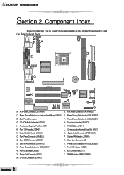
...Front USB Header (JUSB4) Y. Digital Audio Connector (SPDIF_OUT) P. Serial ATA Connectors (JSATA1-2) U. Power Source Selection for USB (JUSBV1) H. BIOSTAR Motherboard Section 2. Accelerated Graphics Port Slot (AGP1) K. ATX Power Connector (JATXPWR2) D. IDE Connectors (IDE1-2) Z. CPU Fan Connector (JCFAN1) ...Power Source Selection for Keyboard and Mouse (JKBV1) E. Component Index This section helps you to locate the components in the motherboard and to find the details about them. Power Source Selection for USB (JUSBV3) V. CD-ROMAudio-InHeader(JCDIN1) I ...
...Front USB Header (JUSB4) Y. Digital Audio Connector (SPDIF_OUT) P. Serial ATA Connectors (JSATA1-2) U. Power Source Selection for USB (JUSBV1) H. BIOSTAR Motherboard Section 2. Accelerated Graphics Port Slot (AGP1) K. ATX Power Connector (JATXPWR2) D. IDE Connectors (IDE1-2) Z. CPU Fan Connector (JCFAN1) ...Power Source Selection for Keyboard and Mouse (JKBV1) E. Component Index This section helps you to locate the components in the motherboard and to find the details about them. Power Source Selection for USB (JUSBV3) V. CD-ROMAudio-InHeader(JCDIN1) I ...
K8VHA M user's manual
Page 7
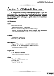
Chipset * North Bridge: VIA K8T800. * South Bridge: VIA VT8237. BIOSTAR Motherboard Section 3. Hardware CPU * Supports Socket 754. * Supports AMD AthlonTM 64 processor. * Processor interface via Hyper-TransportTM Technology. * 800/ 600/ 400/ 200 clock rates with "Double ... Main Memory * Supports 72-bit (64-bits + 8-bits ECC) DDR SDRAM. * Supports 266, 333, 400 and 200 MHz DDR technologies. * Maximum memory size is 2 GB. A. K8VHA-M Features In this section, you shall find all the information about the motherboard in both directions simultaneously.
Chipset * North Bridge: VIA K8T800. * South Bridge: VIA VT8237. BIOSTAR Motherboard Section 3. Hardware CPU * Supports Socket 754. * Supports AMD AthlonTM 64 processor. * Processor interface via Hyper-TransportTM Technology. * 800/ 600/ 400/ 200 clock rates with "Double ... Main Memory * Supports 72-bit (64-bits + 8-bits ECC) DDR SDRAM. * Supports 266, 333, 400 and 200 MHz DDR technologies. * Maximum memory size is 2 GB. A. K8VHA-M Features In this section, you shall find all the information about the motherboard in both directions simultaneously.
K8VHA M user's manual
Page 8
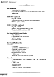
... Mbytes. - 4 USB2.0 ports. - 1 front audio header. - 1 S/PDIF Out header. - 1 IEEE1394 (FirewireTM) port. (optional) English 4 PS/2 mouse and PS/2 keyboard. - 4 USB2.0 ports. - 1 IEEE1394 (FirewireTM) connector. (optional) b. BIOSTAR Motherboard On Board IDE * Supports four IDE disk drives. * Supports PIO Mode 5, Bride Mode and Ultra DMA 33/ 66/ 100/ 133 Bus Master Mode. LAN PHY...
... Mbytes. - 4 USB2.0 ports. - 1 front audio header. - 1 S/PDIF Out header. - 1 IEEE1394 (FirewireTM) port. (optional) English 4 PS/2 mouse and PS/2 keyboard. - 4 USB2.0 ports. - 1 IEEE1394 (FirewireTM) connector. (optional) b. BIOSTAR Motherboard On Board IDE * Supports four IDE disk drives. * Supports PIO Mode 5, Bride Mode and Ultra DMA 33/ 66/ 100/ 133 Bus Master Mode. LAN PHY...
K8VHA M user's manual
Page 9
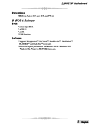
BIOS & Software BIOS * Award legal BIOS. * APM1.2. * ACPI. * USB Function. Software * Supports WarpspeederTM, 9th TouchTM, BootBlockerTM, WinFlasherTM, FLASHERTM and StudioFunTM (optional). * Offers the highest performance for Windows 98 SE, Windows 2000, Windows Me, Windows XP, UNIX Series, etc. 5 English BIOSTAR Motherboard Dimensions ATX Form Factor: 24.4 cm x 24.4 cm (W X L) B.
BIOS & Software BIOS * Award legal BIOS. * APM1.2. * ACPI. * USB Function. Software * Supports WarpspeederTM, 9th TouchTM, BootBlockerTM, WinFlasherTM, FLASHERTM and StudioFunTM (optional). * Offers the highest performance for Windows 98 SE, Windows 2000, Windows Me, Windows XP, UNIX Series, etc. 5 English BIOSTAR Motherboard Dimensions ATX Form Factor: 24.4 cm x 24.4 cm (W X L) B.
K8VHA M user's manual
Page 10
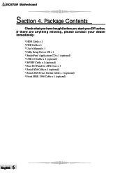
Application CD x 1 (optional) * USB 2.0 Cable x 1 (optional) * S/PDIF Cable x 1 (optional) * Rear I/O Panel for ATX Case x 1 * Serial ATA Cable x 1 (optional) * Serial ATA Power Switch Cable x 1 (optional) * Front IEEE 1394 Cable x 1 (optional) English 6 If there are anything missing, please contact your DIY action. BIOSTAR Motherboard Section 4. Package Contents Check what you have bought before you start your dealer immediately. * HDD Cable x 1 * FDD Cable x 1 * User's Manual x 1 * Fully Setup Driver CD x 1 * StudioFun!
Application CD x 1 (optional) * USB 2.0 Cable x 1 (optional) * S/PDIF Cable x 1 (optional) * Rear I/O Panel for ATX Case x 1 * Serial ATA Cable x 1 (optional) * Serial ATA Power Switch Cable x 1 (optional) * Front IEEE 1394 Cable x 1 (optional) English 6 If there are anything missing, please contact your DIY action. BIOSTAR Motherboard Section 4. Package Contents Check what you have bought before you start your dealer immediately. * HDD Cable x 1 * FDD Cable x 1 * User's Manual x 1 * Fully Setup Driver CD x 1 * StudioFun!
K8VHA M user's manual
Page 11
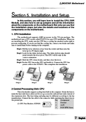
... the fans to make the heat sink fins to allow air flow to go across the onboard heat sinks instead of the components on the motherboard. 1. BIOSTAR Motherboard Section 5. Not only can you are installing the CPU, make sure to the ground pin. When you find the cooling fan, contact your... Installation and Setup In this section, you do not find the installation steps, but also the details and locations of the expansion slots. The motherboard uses a CPU socket called PGA754 for the white dot/cut edge should point towards the lever pivot. If you will fit only in the ...
... the fans to make the heat sink fins to allow air flow to go across the onboard heat sinks instead of the components on the motherboard. 1. BIOSTAR Motherboard Section 5. Not only can you are installing the CPU, make sure to the ground pin. When you find the cooling fan, contact your... Installation and Setup In this section, you do not find the installation steps, but also the details and locations of the expansion slots. The motherboard uses a CPU socket called PGA754 for the white dot/cut edge should point towards the lever pivot. If you will fit only in the ...
K8VHA M user's manual
Page 12
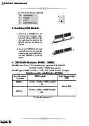
BIOSTAR Motherboard (2) System Fan Header: JSFAN1 Pin Assignment 1 Ground 3 2 +12V 3 FAN RPM Sense 1 3. Align a DIMM on the slot such that the notch on the DIMM matches the ...
BIOSTAR Motherboard (2) System Fan Header: JSFAN1 Pin Assignment 1 Ground 3 2 +12V 3 FAN RPM Sense 1 3. Align a DIMM on the slot such that the notch on the DIMM matches the ...

K8VHA M user's manual
Page 13
BIOSTAR Motherboard 5. This PCI slot is designed as 32 bits. (4) Accelerated Graphics Port Slot: AGP1 Your monitor will take advantage of AGP technology to that supports 360K, ... Pin1-2 close 6. Jumper open ". How to four hard disk drives. This connector supports the provided floppy drive ribbon cables. (2) Hard Disk Connectors: IDE1/ IDE2 The motherboard has a 32-bit Enhanced PCI IDE Controller that provides PIO Mode 0~4, Bus Master, and Ultra DMA 33/ 66/ 100/ 133 functionality.
BIOSTAR Motherboard 5. This PCI slot is designed as 32 bits. (4) Accelerated Graphics Port Slot: AGP1 Your monitor will take advantage of AGP technology to that supports 360K, ... Pin1-2 close 6. Jumper open ". How to four hard disk drives. This connector supports the provided floppy drive ribbon cables. (2) Hard Disk Connectors: IDE1/ IDE2 The motherboard has a 32-bit Enhanced PCI IDE Controller that provides PIO Mode 0~4, Bus Master, and Ultra DMA 33/ 66/ 100/ 133 functionality.
K8VHA M user's manual
Page 14
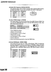
... the jumper to "Pin 2-3 Close". 3. Reset your desired password or clear the CMOS data. (8) Front USB Header: JUSB3/ JUSB4 The motherboard provides two USB 2.0 Pin Header. You can transfer data with 2 channels SATA interface. Wait for connecting high-speed USB interface peripherals such as...SATA 1.0 spec and can erase the CMOS RTC Ram data to clear the Real Time Clock (RTC) Ram in CMOS. BIOSTAR Motherboard (6) Serial ATA Connector: JSATA1/ JSATA2 The motherboard has a PCI to a maximum of date, time, and system setup parameters. 13 JCMOS1 Assignment Pin 1-2 Close Normal Operation...
... the jumper to "Pin 2-3 Close". 3. Reset your desired password or clear the CMOS data. (8) Front USB Header: JUSB3/ JUSB4 The motherboard provides two USB 2.0 Pin Header. You can transfer data with 2 channels SATA interface. Wait for connecting high-speed USB interface peripherals such as...SATA 1.0 spec and can erase the CMOS RTC Ram data to clear the Real Time Clock (RTC) Ram in CMOS. BIOSTAR Motherboard (6) Serial ATA Connector: JSATA1/ JSATA2 The motherboard has a PCI to a maximum of date, time, and system setup parameters. 13 JCMOS1 Assignment Pin 1-2 Close Normal Operation...
K8VHA M user's manual
Page 15
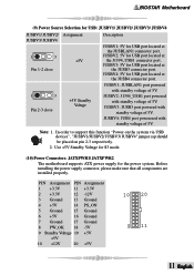
Note: 1. BIOSTAR Motherboard (9) Power Source Selection for USB: JUSBV1/ JUSBV2/ JUSBV3/ JUSBV4 JUSBV1/ JUSBV2/ Assignment JUSBV3/ JUSBV4 Description 1 3 +5V Pin 1-2 close +5V Standby Voltage JUSBV1: JUSBLAN1 port powered ... that all components are installed properly. JUSBV3: 5V for the power system. Use +5V Standby Voltage for S3 mode. (10) Power Connectors: JATXPWR1/ JATXPWR2 The motherboard supports ATX power supply for USB port located at the JUSB4 connector port. 1 3 Pin 2-3 close JUSBV1: 5V for USB port located at the J1394_USB1 connector...
Note: 1. BIOSTAR Motherboard (9) Power Source Selection for USB: JUSBV1/ JUSBV2/ JUSBV3/ JUSBV4 JUSBV1/ JUSBV2/ Assignment JUSBV3/ JUSBV4 Description 1 3 +5V Pin 1-2 close +5V Standby Voltage JUSBV1: JUSBLAN1 port powered ... that all components are installed properly. JUSBV3: 5V for the power system. Use +5V Standby Voltage for S3 mode. (10) Power Connectors: JATXPWR1/ JATXPWR2 The motherboard supports ATX power supply for USB port located at the JUSB4 connector port. 1 3 Pin 2-3 close JUSBV1: 5V for USB port located at the J1394_USB1 connector...

K8VHA M user's manual
Page 16
BIOSTAR Motherboard PIN Assignment PIN Assignment 1 +12V 3 Ground 2 +12V 4 Ground 2 1 4 (11) Front 1394 Header: J1394B1 Pin Assignment Pin Assignment 1 A1+ 3 Ground 2 A14 Ground 9 1 5 B1+ 6 B1- 10 2 7 +12V 8 +...
BIOSTAR Motherboard PIN Assignment PIN Assignment 1 +12V 3 Ground 2 +12V 4 Ground 2 1 4 (11) Front 1394 Header: J1394B1 Pin Assignment Pin Assignment 1 A1+ 3 Ground 2 A14 Ground 9 1 5 B1+ 6 B1- 10 2 7 +12V 8 +...
K8VHA M user's manual
Page 17
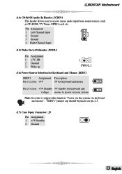
BIOSTAR Motherboard (14) CD-ROM Audio-In Header: JCDIN1 This header allows you to support this function "Power-on the system via keyboard and mouse", "JKBV1" jumper ...
BIOSTAR Motherboard (14) CD-ROM Audio-In Header: JCDIN1 This header allows you to support this function "Power-on the system via keyboard and mouse", "JKBV1" jumper ...
K8VHA M user's manual
Page 18
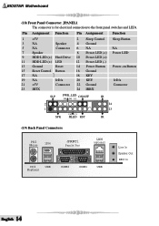
...) Back Panel Connectors PS/2 Mouse 1394 JPRNT1 Parallel Port LAN (optional) PS/2 USB Keyboard COM2 COM1 USB Line In Speaker Out MIC In English 14 BIOSTAR Motherboard (18) Front Panel Connector: JPANEL1 The connector is for electrical connection to the front panel switches and LEDs.
...) Back Panel Connectors PS/2 Mouse 1394 JPRNT1 Parallel Port LAN (optional) PS/2 USB Keyboard COM2 COM1 USB Line In Speaker Out MIC In English 14 BIOSTAR Motherboard (18) Front Panel Connector: JPANEL1 The connector is for electrical connection to the front panel switches and LEDs.

K8VHA M user's manual
Page 19
BIOSTAR Motherboard 6 Channel Speakers Speaker Out/ Front Speaker (Right & Left) Line In/ Rear Speaker (Left & Right) Mic In/ Center & Bass 15 English
BIOSTAR Motherboard 6 Channel Speakers Speaker Out/ Front Speaker (Right & Left) Line In/ Rear Speaker (Left & Right) Mic In/ Center & Bass 15 English

K8VHA M user's manual
Page 20
... the hard drive. power light * Make sure power cable is spinning. System inoperative. Then, Error message reading "SECTOR NOT low-level format, partition, and high- BIOSTAR Motherboard Section 6. Screen message says "Invalid Configuration" or "CMOS Failure." * Review system's equipment.
... the hard drive. power light * Make sure power cable is spinning. System inoperative. Then, Error message reading "SECTOR NOT low-level format, partition, and high- BIOSTAR Motherboard Section 6. Screen message says "Invalid Configuration" or "CMOS Failure." * Review system's equipment.

