User Manual
Page 1
R TX97-X Pentium® ATX Motherboard USER'S MANUAL
R TX97-X Pentium® ATX Motherboard USER'S MANUAL
User Manual
Page 4
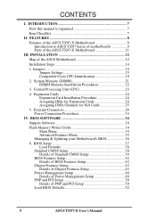
INSTALLATION 12 Map of PNP and PCI Setup 50 Load BIOS Defaults 52 4 ASUS TX97-X User's Manual Expansion Cards 24 Expansion Card Installation Procedure 24 Assigning IRQs for Expansion Cards 24 Assigning DMA Channels... Management Setup 48 PNP and PCI Setup 50 Details of the ASUS Motherboard 12 Installation Steps 14 1. External Connectors 26 Power Connection Procedures 33 IV. FEATURES 8 Features of the ASUS TX97-X Motherboard 8 Introduction to ASUS TX97 Series of motherboards 9 Parts of the ASUS TX97-X Motherboard 11 III. CONTENTS I. System Memory (DIMM 21 DIMM Memory ...
INSTALLATION 12 Map of PNP and PCI Setup 50 Load BIOS Defaults 52 4 ASUS TX97-X User's Manual Expansion Cards 24 Expansion Card Installation Procedure 24 Assigning IRQs for Expansion Cards 24 Assigning DMA Channels... Management Setup 48 PNP and PCI Setup 50 Details of the ASUS Motherboard 12 Installation Steps 14 1. External Connectors 26 Power Connection Procedures 33 IV. FEATURES 8 Features of the ASUS TX97-X Motherboard 8 Introduction to ASUS TX97 Series of motherboards 9 Parts of the ASUS TX97-X Motherboard 11 III. CONTENTS I. System Memory (DIMM 21 DIMM Memory ...
User Manual
Page 5
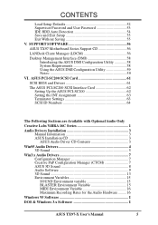
...16 Maximum Recording Rates for the Audio Hardware ......... 16 Windows 95 Software I DOS & Windows 3.x Software I ASUS TX97-X User's Manual 5 SUPPORT SOFTWARE 56 ASUS TX97 Motherboard Series Support CD 56 LANDesk Client Manager (LDCM 56 Desktop Management Interface (DMI 58 Introducing the... ASUS DMI Configuration Utility 58 System Requirements 58 Using the ASUS DMI Configuration Utility 59 Notes 59 VI. CONTENTS Load Setup ...
...16 Maximum Recording Rates for the Audio Hardware ......... 16 Windows 95 Software I DOS & Windows 3.x Software I ASUS TX97-X User's Manual 5 SUPPORT SOFTWARE 56 ASUS TX97 Motherboard Series Support CD 56 LANDesk Client Manager (LDCM 56 Desktop Management Interface (DMI 58 Introducing the... ASUS DMI Configuration Utility 58 System Requirements 58 Using the ASUS DMI Configuration Utility 59 Notes 59 VI. CONTENTS Load Setup ...
User Manual
Page 7
.... IV. DMI Utility: BIOS supported Desktop Management Interface VI. DOS/Win3.1x: Audio Software Section (optional) Item Checklist Please check that your retailer. √ The ASUS TX97-X motherboard √ 1 IDE ribbon cable √ 1 floppy ribbon cable √ Support drivers and utilities as follows (view FILELIST.TXT for details) • LANDesk Client Manager (LDCM...
.... IV. DMI Utility: BIOS supported Desktop Management Interface VI. DOS/Win3.1x: Audio Software Section (optional) Item Checklist Please check that your retailer. √ The ASUS TX97-X motherboard √ 1 IDE ribbon cable √ 1 floppy ribbon cable √ Support drivers and utilities as follows (view FILELIST.TXT for details) • LANDesk Client Manager (LDCM...
User Manual
Page 8
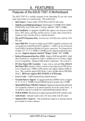
...Audio Ready: Optional Creative Labs 16C Series Audio with EPP and ECP capabilities. A second IrDA connector is carefully designed for wireless interface. 8 ASUS TX97-X User's Manual Supports Japanese standard "Floppy 3 mode" (3.5" 1.2MB). • Desktop Management Interface (DMI): Supports DMI through BIOS which...Comes with an onboard Ultra DMA/33 Bus Master IDE controller with two connectors that supports auto detection of the ASUS TX97-X Motherboard The ASUS TX97-X is available for a standard individual infrared cable set to mount the connectors to an unused expansion slot on the...
...Audio Ready: Optional Creative Labs 16C Series Audio with EPP and ECP capabilities. A second IrDA connector is carefully designed for wireless interface. 8 ASUS TX97-X User's Manual Supports Japanese standard "Floppy 3 mode" (3.5" 1.2MB). • Desktop Management Interface (DMI): Supports DMI through BIOS which...Comes with an onboard Ultra DMA/33 Bus Master IDE controller with two connectors that supports auto detection of the ASUS TX97-X Motherboard The ASUS TX97-X is available for a standard individual infrared cable set to mount the connectors to an unused expansion slot on the...
User Manual
Page 9
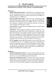
... implemented on the following high-level goals: Support for Plug and Play compatibility and power management for configuring and managing all ASUS 430TX series of motherboards. ASUS TX97-X User's Manual 9 The best of motherboards with existing ATA-2 IDE specs so there is compatible with Intel 430TX PCIset improves IDE transfer rate using EDO memory to...
... implemented on the following high-level goals: Support for Plug and Play compatibility and power management for configuring and managing all ASUS 430TX series of motherboards. ASUS TX97-X User's Manual 9 The best of motherboards with existing ATA-2 IDE specs so there is compatible with Intel 430TX PCIset improves IDE transfer rate using EDO memory to...
User Manual
Page 10
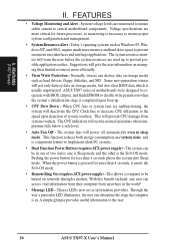
... the stage the computer is completed upon detection of system overheat. System voltage levels are used up . • CPU Slow Down - ASUS TX97 series of two states, one is Sleep mode and the other is usually unprotected. FEATURES • Voltage Monitoring and Alert - This will... energy consumption and system noise, and is a important feature to disable write permission when the system's initialization stage is in one of motherboards were designed to cooperate with BIOS, chipset, and flash EPROM to implement silent PC systems. • Dual Function Power Button (requires ATX...
... the stage the computer is completed upon detection of system overheat. System voltage levels are used up . • CPU Slow Down - ASUS TX97 series of two states, one is Sleep mode and the other is usually unprotected. FEATURES • Voltage Monitoring and Alert - This will... energy consumption and system noise, and is a important feature to disable write permission when the system's initialization stage is in one of motherboards were designed to cooperate with BIOS, chipset, and flash EPROM to implement silent PC systems. • Dual Function Power Button (requires ATX...
User Manual
Page 11
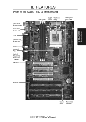
FEATURES Parts of Board) II. B: Serial Conn. COM 2 Intel's 430TX PCIset (Optional) T:Joystick/Midi B:1/8" Output/ Input/Mic 4 PCI Slots Floppy Drive Connector IDE 2 Connector IDE 1 Connector 512KB Pipelined Burst L2 Cache 4 ISA Slots Hardware Programmable Monitor Flash ROM ASUS TX97-X User's Manual 11 II. FEATURES (Parts of the ASUS TX97-X Motherboard T: PS/2 Mouse B: PS/2 Keyboard T: USB Port 1 B: USB Port 2 CPU ZIF CPU Thermal 3 DIMM Sockets Socket 7 Sensor COM 1 T: Parallel Conn.
FEATURES Parts of Board) II. B: Serial Conn. COM 2 Intel's 430TX PCIset (Optional) T:Joystick/Midi B:1/8" Output/ Input/Mic 4 PCI Slots Floppy Drive Connector IDE 2 Connector IDE 1 Connector 512KB Pipelined Burst L2 Cache 4 ISA Slots Hardware Programmable Monitor Flash ROM ASUS TX97-X User's Manual 11 II. FEATURES (Parts of the ASUS TX97-X Motherboard T: PS/2 Mouse B: PS/2 Keyboard T: USB Port 1 B: USB Port 2 CPU ZIF CPU Thermal 3 DIMM Sockets Socket 7 Sensor COM 1 T: Parallel Conn.

User Manual
Page 12
... (Map of the ASUS Motherboard COM 1 PS/2 Top: Mouse Bottom: Keyboard FANPWR3 12V USB Top: USB 1 Bottom: USB 2 Multi-I/O (En/Dis) SIO Board Power Input for BIOS Infrared Con. (IrDA) ISA Slot 4 Panel Connections IDE LED NOTE: The items in Outline are available only with the optional onboard Audio. 12 ASUS TX97-X User's Manual...
... (Map of the ASUS Motherboard COM 1 PS/2 Top: Mouse Bottom: Keyboard FANPWR3 12V USB Top: USB 1 Bottom: USB 2 Multi-I/O (En/Dis) SIO Board Power Input for BIOS Infrared Con. (IrDA) ISA Slot 4 Panel Connections IDE LED NOTE: The items in Outline are available only with the optional onboard Audio. 12 ASUS TX97-X User's Manual...

User Manual
Page 13
... Switch Lead (2-pins) p. 31 Reset Switch Lead (2-pins) p. 31 Keyboard Lock Switch Lead (5-pins) p. 31 Speaker Output Connector (4-pins) p. 32 Infrared Port Module Connector p. 32 Motherboard Power Connector (20-pin Block) ASUS TX97-X User's Manual 13
... Switch Lead (2-pins) p. 31 Reset Switch Lead (2-pins) p. 31 Keyboard Lock Switch Lead (5-pins) p. 31 Speaker Output Connector (4-pins) p. 32 Infrared Port Module Connector p. 32 Motherboard Power Connector (20-pin Block) ASUS TX97-X User's Manual 13
User Manual
Page 14
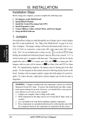
...respec- The jumpers will be shown graphically such as [----], [1-2], [2-3] for our motherboards is written besides pin 1 on the inside. 2. Settings with two pins will be sharing pins from the system. 14 ASUS TX97-X User's Manual Hold components by the edges and try not to connect pins... 2&3. Set Jumpers on your computer. 1. To protect the motherboard and other groups. Install DRAM Modules 3. Jumpers Several hardware ...
...respec- The jumpers will be shown graphically such as [----], [1-2], [2-3] for our motherboards is written besides pin 1 on the inside. 2. Settings with two pins will be sharing pins from the system. 14 ASUS TX97-X User's Manual Hold components by the edges and try not to connect pins... 2&3. Set Jumpers on your computer. 1. To protect the motherboard and other groups. Install DRAM Modules 3. Jumpers Several hardware ...
User Manual
Page 17
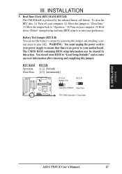
... 1&2. INSTALLATION (Jumpers) ASUS TX97-X User's Manual 17 You should enter BIOS to "Load Setup Defaults" and re-enter any user information after removing and reapplying this jumper to "Clear Data," (3) Move the jumper back to "Operation," (4) Turn on your computer, (5) Hold down during bootup and enter BIOS setup to your motherboard. To clear...
... 1&2. INSTALLATION (Jumpers) ASUS TX97-X User's Manual 17 You should enter BIOS to "Load Setup Defaults" and re-enter any user information after removing and reapplying this jumper to "Clear Data," (3) Move the jumper back to "Operation," (4) Turn on your computer, (5) Hold down during bootup and enter BIOS setup to your motherboard. To clear...

User Manual
Page 18
...Ratio (BF0, BF1) These jumpers set together with the Cyrix 166+ installed on this motherboard. 18 ASUS TX97-X User's Manual These allow the selection of the Intel, AMD, or Cyrix CPU as ...) BF1 BF0 [2-3] [1-2] [2-3] [2-3] [2-3] [2-3] [1-2] [2-3] [1-2] [2-3] [1-2] [1-2] [1-2] [1-2] [1-2] [1-2] [1-2] [1-2] [1-2] [1-2] [1-2] [1-2] [1-2] [1-2] [1-2] [1-2] [1-2] [2-3] *NOTE: Only Cyrix Revision 2.7 or later is supported on this motherboard. Bootup screen will show 6x86-P166+ with the above jumpers CPU External (BUS) Frequency Selection. FS0 FS1 FS2 FS0 FS1 FS2 FS0 FS1 FS2 FS0 ...
...Ratio (BF0, BF1) These jumpers set together with the Cyrix 166+ installed on this motherboard. 18 ASUS TX97-X User's Manual These allow the selection of the Intel, AMD, or Cyrix CPU as ...) BF1 BF0 [2-3] [1-2] [2-3] [2-3] [2-3] [2-3] [1-2] [2-3] [1-2] [2-3] [1-2] [1-2] [1-2] [1-2] [1-2] [1-2] [1-2] [1-2] [1-2] [1-2] [1-2] [1-2] [1-2] [1-2] [1-2] [1-2] [1-2] [2-3] *NOTE: Only Cyrix Revision 2.7 or later is supported on this motherboard. Bootup screen will show 6x86-P166+ with the above jumpers CPU External (BUS) Frequency Selection. FS0 FS1 FS2 FS0 FS1 FS2 FS0 FS1 FS2 FS0 ...

User Manual
Page 19
... 2.7Volt 1 2 3 2.8Volt 1 2 3 2.9Volt VID0 VID1 VID2 VID0 VID1 VID2 VID0 VID1 VID2 1 1 2 2 3 3 3.1Volt 3.4Volt Voltage Regulator Output Selection 1 2 3 3.5Volt R ASUS TX97-X User's Manual 19 Currently Intel's new Pentium P55C MMX 200MHz with Dual Power Planes is labeled Cyrix 6x86 P166+ but must be Revision 2.7 and later... between Single Power Plane and Dual Power Planes. The number should read G8DC6620A or larger. 8. Look on this motherboard is supported at 2.8Volts. INSTALLATION Compatible Cyrix CPU Identification The only Cyrix CPU that is supported on the underside ...
... 2.7Volt 1 2 3 2.8Volt 1 2 3 2.9Volt VID0 VID1 VID2 VID0 VID1 VID2 VID0 VID1 VID2 1 1 2 2 3 3 3.1Volt 3.4Volt Voltage Regulator Output Selection 1 2 3 3.5Volt R ASUS TX97-X User's Manual 19 Currently Intel's new Pentium P55C MMX 200MHz with Dual Power Planes is labeled Cyrix 6x86 P166+ but must be Revision 2.7 and later... between Single Power Plane and Dual Power Planes. The number should read G8DC6620A or larger. 8. Look on this motherboard is supported at 2.8Volts. INSTALLATION Compatible Cyrix CPU Identification The only Cyrix CPU that is supported on the underside ...
User Manual
Page 21
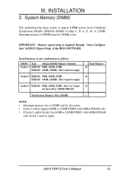
... Memory Modules Socket 1 SDRAM 8MB, 16MB, 32MB SDRAM 64MB, 128MB - III. Maximum memory of either 8, 16, or 32, 64, or 128MB. ASUS TX97-X User's Manual 21 IMPORTANT: Memory speed setup is 256MB total for all sockets. • Socket 3 will not support 64MB or 128MB DIMMs with 64Mbit ... SDRAM cells, Socket 3 must be empty Socket 3 SDRAM 8MB, 16MB, 32MB - Slot 3 must be 256MB or less. System Memory (DIMM) This motherboard has three sockets to support 3.3Volt (power level) Unbuffered Synchronous DRAMs (SDRAM) DIMMs of DIMMs must be empty Total Memory x1 Socket 2 SDRAM 8MB, ...
... Memory Modules Socket 1 SDRAM 8MB, 16MB, 32MB SDRAM 64MB, 128MB - III. Maximum memory of either 8, 16, or 32, 64, or 128MB. ASUS TX97-X User's Manual 21 IMPORTANT: Memory speed setup is 256MB total for all sockets. • Socket 3 will not support 64MB or 128MB DIMMs with 64Mbit ... SDRAM cells, Socket 3 must be empty Socket 3 SDRAM 8MB, 16MB, 32MB - Slot 3 must be 256MB or less. System Memory (DIMM) This motherboard has three sockets to support 3.3Volt (power level) Unbuffered Synchronous DRAMs (SDRAM) DIMMs of DIMMs must be empty Total Memory x1 Socket 2 SDRAM 8MB, ...
User Manual
Page 22
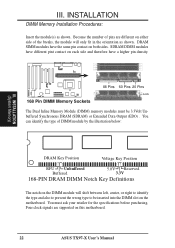
... Procedures: Insert the module(s) as shown. SDRAM DIMM modules have different pint contact on each side and therefore have the same pin contact on this motherboard. 22 ASUS TX97-X User's Manual III. DRAM SIMM modules have a higher pin density. 168 Pin DIMM Memory Sockets 88 Pins 60 Pins 20 Pins Lock The Dual... (System Memory) DRAM Key Position Voltage Key Position RFU Unbuffered Buffered 5.0V Reserved 3.3V 168-PIN DRAM DIMM Notch Key Definitions The notch on the motherboard.
... Procedures: Insert the module(s) as shown. SDRAM DIMM modules have different pint contact on each side and therefore have the same pin contact on this motherboard. 22 ASUS TX97-X User's Manual III. DRAM SIMM modules have a higher pin density. 168 Pin DIMM Memory Sockets 88 Pins 60 Pins 20 Pins Lock The Dual... (System Memory) DRAM Key Position Voltage Key Position RFU Unbuffered Buffered 5.0V Reserved 3.3V 168-PIN DRAM DIMM Notch Key Definitions The notch on the motherboard.
User Manual
Page 23
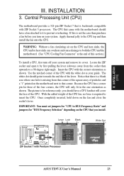
... Unit (CPU) The motherboard provides a 321-pin ZIF Socket 7 that you turn off your system and remove its cover. Locate the ZIF socket and open it to insert the CPU. you should point towards the end the of this is backwards compatible with Pentium Processor ASUS TX97-X User's Manual 23 ... a CPU, first turn on the fan and close the socket's lever. Use the notched corner of pin holes and a "1" printed on the motherboard next to BUS Frequency Ratio" and jumpers for "CPU to that there is a blank area where one orientation as your system. Once completely inserted,...
... Unit (CPU) The motherboard provides a 321-pin ZIF Socket 7 that you turn off your system and remove its cover. Locate the ZIF socket and open it to insert the CPU. you should point towards the end the of this is backwards compatible with Pentium Processor ASUS TX97-X User's Manual 23 ... a CPU, first turn on the fan and close the socket's lever. Use the notched corner of pin holes and a "1" printed on the motherboard next to BUS Frequency Ratio" and jumpers for "CPU to that there is a blank area where one orientation as your system. Once completely inserted,...
User Manual
Page 24
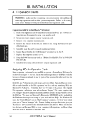
In an standard design there are 16 IRQs available but most of them are already in use at the same time. 24 ASUS TX97-X User's Manual You may cause severe damage to use the same IRQs or your computer system's cover. 4. Set any necessary ... 2. Read your expansion card documentation on the slot you unplug your expansion card. The original ISA expansion card design, now referred to setup your motherboard and expansion cards. Replace the computer system's cover. 8. System IRQs are then used and free IRQs. III. INSTALLATION 4. Expansion Cards WARNING: ...
In an standard design there are 16 IRQs available but most of them are already in use at the same time. 24 ASUS TX97-X User's Manual You may cause severe damage to use the same IRQs or your computer system's cover. 4. Set any necessary ... 2. Read your expansion card documentation on the slot you unplug your expansion card. The original ISA expansion card design, now referred to setup your motherboard and expansion cards. Replace the computer system's cover. 8. System IRQs are then used and free IRQs. III. INSTALLATION 4. Expansion Cards WARNING: ...
User Manual
Page 25
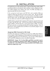
... ISA Configuration Utility. INSTALLATION (D(CMoAnCnhecatnonrsel)s) ASUS TX97-X User's Manual 25 DMA assignments for ISA Cards Some ISA cards, both Legacy and PNP ISA cards installed, IRQs are assigned to a PCI slot that has a card in it that the jumpers on this motherboard use a DMA (Direct Memory Access)...also need to set to PCI expansion cards after those not used by Legacy cards. III. INSTALLATION To simplify this process this motherboard are assigned automatically from those used by Legacy cards. For PNP cards, IRQs are handled the same way as the IRQ assignment ...
... ISA Configuration Utility. INSTALLATION (D(CMoAnCnhecatnonrsel)s) ASUS TX97-X User's Manual 25 DMA assignments for ISA Cards Some ISA cards, both Legacy and PNP ISA cards installed, IRQs are assigned to a PCI slot that has a card in it that the jumpers on this motherboard use a DMA (Direct Memory Access)...also need to set to PCI expansion cards after those not used by Legacy cards. III. INSTALLATION To simplify this process this motherboard are assigned automatically from those used by Legacy cards. For PNP cards, IRQs are handled the same way as the IRQ assignment ...
User Manual
Page 26
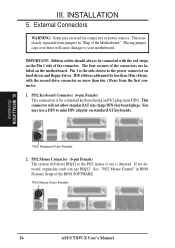
IMPORTANT: Ribbon cables should always be less than 6in. (15cm) from jumpers in BIOS Features Setup of the Motherboard." Pin 1 is for connectors or power sources. PS/2 Mouse (6-pin Female) 26 ASUS TX97-X User's Manual The four corners of the connector. IDE ribbon cable must be connected with the second drive connector no more...
IMPORTANT: Ribbon cables should always be less than 6in. (15cm) from jumpers in BIOS Features Setup of the Motherboard." Pin 1 is for connectors or power sources. PS/2 Mouse (6-pin Female) 26 ASUS TX97-X User's Manual The four corners of the connector. IDE ribbon cable must be connected with the second drive connector no more...


