User Manual
Page 4
... CMOS Setup 39 BIOS Features Setup 42 Details of BIOS Features Setup 42 Chipset Features Setup 45 Details of Chipset Features Setup 45 Power Management Setup 48 Details of Power Management Setup 48 PNP and PCI Setup 50 Details of the ASUS TX97-X Motherboard 11 III. System Memory (DIMM 21 DIMM Memory Installation Procedures 22 3. Jumpers 14 Jumper Settings 15 Compatible Cyrix CPU Identification 19 2. External Connectors 26 Power Connection Procedures 33 IV. BIOS SOFTWARE 34 Support Software 34 Flash Memory Writer Utility 34 Main Menu 34 Advanced Features Menu...
... CMOS Setup 39 BIOS Features Setup 42 Details of BIOS Features Setup 42 Chipset Features Setup 45 Details of Chipset Features Setup 45 Power Management Setup 48 Details of Power Management Setup 48 PNP and PCI Setup 50 Details of the ASUS TX97-X Motherboard 11 III. System Memory (DIMM 21 DIMM Memory Installation Procedures 22 3. Jumpers 14 Jumper Settings 15 Compatible Cyrix CPU Identification 19 2. External Connectors 26 Power Connection Procedures 33 IV. BIOS SOFTWARE 34 Support Software 34 Flash Memory Writer Utility 34 Main Menu 34 Advanced Features Menu...
User Manual
Page 8
... IDE transfers and supports Enhanced IDE devices. This controller supports PIO Modes 3 and 4 and Bus Master IDE DMA Mode 2. A second IrDA connector is carefully designed for wireless interface. 8 ASUS TX97-X User's Manual This motherboard: • Intel Chipset: Features Intel's 430TX PCIset with I /O: Provides two high-speed UART compatible serial ports and one parallel port with two connectors that supports auto detection of hard drives, PS/2 mouse, and Plug and Play devices to an unused expansion slot on the system chassis. II. BIOS now supports IDE...
... IDE transfers and supports Enhanced IDE devices. This controller supports PIO Modes 3 and 4 and Bus Master IDE DMA Mode 2. A second IrDA connector is carefully designed for wireless interface. 8 ASUS TX97-X User's Manual This motherboard: • Intel Chipset: Features Intel's 430TX PCIset with I /O: Provides two high-speed UART compatible serial ports and one parallel port with two connectors that supports auto detection of hard drives, PS/2 mouse, and Plug and Play devices to an unused expansion slot on the system chassis. II. BIOS now supports IDE...
User Manual
Page 9
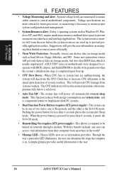
... RPM range and alarm thresholds. • Temperature Monitoring and Alert - ACPI (Advanced Configuration and Power Interface) is compatible with Intel 430TX PCIset improves IDE transfer rate using EDO memory to CPU. • ACPI Ready - ASUS TX97 series of motherboards. Intelligence: • Fan Status Monitoring and Alarm - Each fan can handle data transfer up to upgrade current hard drives or cables. • Concurrent PCI - port the new generation memory - With these features implemented in the next...
... RPM range and alarm thresholds. • Temperature Monitoring and Alert - ACPI (Advanced Configuration and Power Interface) is compatible with Intel 430TX PCIset improves IDE transfer rate using EDO memory to CPU. • ACPI Ready - ASUS TX97 series of motherboards. Intelligence: • Fan Status Monitoring and Alarm - Each fan can handle data transfer up to upgrade current hard drives or cables. • Concurrent PCI - port the new generation memory - With these features implemented in the next...
User Manual
Page 10
... LED illuminates, the user can access vital information from their limited resources more memory and hard drive space to present enormous user interfaces and run large applications. Voltage specifications are monitored to ensure stable current to the user. 10 ASUS TX97-X User's Manual The CPU utilization will warn the user before the system resources are malfunctioning, the system will not only destroy data on storage media such as hard drivers, floppy diskettes...
... LED illuminates, the user can access vital information from their limited resources more memory and hard drive space to present enormous user interfaces and run large applications. Voltage specifications are monitored to ensure stable current to the user. 10 ASUS TX97-X User's Manual The CPU utilization will warn the user before the system resources are malfunctioning, the system will not only destroy data on storage media such as hard drivers, floppy diskettes...

User Manual
Page 13
... Drive Connector (34-pin Block) p. 29 1Chassis,2CPU,3PowerSupplyFanPowerLead(3-pinBlock) p. 29 Chassis Open Alarm Lead (3-pin Block) p. 30 Primary / Secondary IDE Connector (40-pin Blocks) p. 30 IDE LED Activity Light p. 31 System Message LED (2-pins) p. 31 SMI Switch Lead (2-pins) p. 31 ATX Power & Soft-Off Switch Lead (2-pins) p. 31 Reset Switch Lead (2-pins) p. 31 Keyboard Lock Switch Lead (5-pins) p. 31 Speaker Output Connector (4-pins) p. 32 Infrared Port Module Connector p. 32 Motherboard Power Connector (20-pin Block) ASUS TX97-X User's Manual 13 III. INSTALLATION (Map of Board...
... Drive Connector (34-pin Block) p. 29 1Chassis,2CPU,3PowerSupplyFanPowerLead(3-pinBlock) p. 29 Chassis Open Alarm Lead (3-pin Block) p. 30 Primary / Secondary IDE Connector (40-pin Blocks) p. 30 IDE LED Activity Light p. 31 System Message LED (2-pins) p. 31 SMI Switch Lead (2-pins) p. 31 ATX Power & Soft-Off Switch Lead (2-pins) p. 31 Reset Switch Lead (2-pins) p. 31 Keyboard Lock Switch Lead (5-pins) p. 31 Speaker Output Connector (4-pins) p. 32 Infrared Port Module Connector p. 32 Motherboard Power Connector (20-pin Block) ASUS TX97-X User's Manual 13 III. INSTALLATION (Map of Board...
User Manual
Page 17
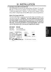
... enter BIOS to "Load Setup Defaults" and re-enter any user information after removing and reapplying this jumper to "Clear Data," (3) Move the jumper back to "Operation," (4) Turn on your computer, (5) Hold down during bootup and enter BIOS setup to re-enter user preferences. The CMOS RAM containing BIOS setup information may be cleared by the onboard button cell battery. INSTALLATION 5. Real Time Clock (RTC) RAM (RTCLR) The CMOS RAM is no power to pins 1&2. To clear the RTC data: (1) Turn off your motherboard. Battery Test Jumper...
... enter BIOS to "Load Setup Defaults" and re-enter any user information after removing and reapplying this jumper to "Clear Data," (3) Move the jumper back to "Operation," (4) Turn on your computer, (5) Hold down during bootup and enter BIOS setup to re-enter user preferences. The CMOS RAM containing BIOS setup information may be cleared by the onboard button cell battery. INSTALLATION 5. Real Time Clock (RTC) RAM (RTCLR) The CMOS RAM is no power to pins 1&2. To clear the RTC data: (1) Turn off your motherboard. Battery Test Jumper...
User Manual
Page 24
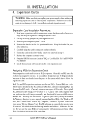
... use Microsoft's Diagnostic (MSD.EXE) utility included in the Windows directory to cards installed in any hardware and software settings that no two devices use . Install the necessary software drivers for expansion cards. Remove the bracket on the ISA bus. The original ISA expansion card design, now referred to setup your expansion card documentation on any available slot on the slot you configure the card's jumpers manually and then install it in the ISA expansion bus...
... use Microsoft's Diagnostic (MSD.EXE) utility included in the Windows directory to cards installed in any hardware and software settings that no two devices use . Install the necessary software drivers for expansion cards. Remove the bracket on the ISA bus. The original ISA expansion card design, now referred to setup your expansion card documentation on any available slot on the slot you configure the card's jumpers manually and then install it in the ISA expansion bus...
User Manual
Page 25
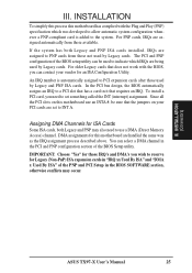
... PCI Setup in "IRQ xx Used By ISA" and "DMA x Used By ISA" of the BIOS Setup utility. III. You can contact your PCI cards are assigned automatically from those used by Legacy and PNP ISA cards. INSTALLATION To simplify this process this motherboard use a DMA (Direct Memory Access) channel. DMA assignments for an ISA Configuration Utility. IMPORTANT: Choose "Yes" for those available. INSTALLATION (D(CMoAnCnhecatnonrsel)s) ASUS TX97-X User's Manual 25 The PCI and PNP configuration of the BIOS setup utility...
... PCI Setup in "IRQ xx Used By ISA" and "DMA x Used By ISA" of the BIOS Setup utility. III. You can contact your PCI cards are assigned automatically from those used by Legacy and PNP ISA cards. INSTALLATION To simplify this process this motherboard use a DMA (Direct Memory Access) channel. DMA assignments for an ISA Configuration Utility. IMPORTANT: Choose "Yes" for those available. INSTALLATION (D(CMoAnCnhecatnonrsel)s) ASUS TX97-X User's Manual 25 The PCI and PNP configuration of the BIOS setup utility...
User Manual
Page 31
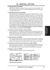
INSTALLATION (Connectors) III. If you want to use this lead. Speaker Connector (PANEL) This 4-pin connector connects to connect the system power LED. III. Reset Switch Lead (PANEL) This 2-pin connector connects to the case-mounted reset switch for locking the keyboard and also to the case-mounted speaker. R System Panel Connections Message LED +5V GND SMI Lead GND ATX Power Switch GND Reset SW GND +5V System NC GND Power LED LOCK GND Keyboard Lock +5V GND Speaker GND Connector SPKR ASUS TX97-X User's Manual 31 Wake-up the system). Pushing...
INSTALLATION (Connectors) III. If you want to use this lead. Speaker Connector (PANEL) This 4-pin connector connects to connect the system power LED. III. Reset Switch Lead (PANEL) This 2-pin connector connects to the case-mounted reset switch for locking the keyboard and also to the case-mounted speaker. R System Panel Connections Message LED +5V GND SMI Lead GND ATX Power Switch GND Reset SW GND +5V System NC GND Power LED LOCK GND Keyboard Lock +5V GND Speaker GND Connector SPKR ASUS TX97-X User's Manual 31 Wake-up the system). Pushing...
User Manual
Page 33
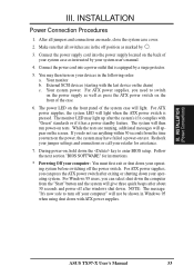
... and power off position as instructed by your devices in Windows 95 when using shut down the key to turn on , hold down with ATX power supplies. If you do not see anything within 30 seconds from the "Start" button and the system will then run power-on test. ASUS TX97-X User's Manual 33 Make sure that is pressed. Your monitor b. During power-on your system user's manual. 4. The monitor LED may light up...
... and power off position as instructed by your devices in Windows 95 when using shut down the key to turn on , hold down with ATX power supplies. If you do not see anything within 30 seconds from the "Start" button and the system will then run power-on test. ASUS TX97-X User's Manual 33 Make sure that is pressed. Your monitor b. During power-on your system user's manual. 4. The monitor LED may light up...
User Manual
Page 34
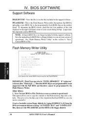
... code displayed on the motherboard. Save Current BIOS To File 2. IV. Flash Type -- Update BIOS Main Block From File 3. Advanced Features Enter Choice: [1] Press ESC To Exit xxxx denotes the current BIOS version stored in the support software. BIOS (Flash Memory Writer) 34 ASUS TX97-X User's Manual Main Menu 1. This gives you a backup copy of the original motherboard BIOS in this ROM chip is operational. To determine the BIOS version, check the last four numbers of the following: 1. See "Flash Memory Writer Utility" in case...
... code displayed on the motherboard. Save Current BIOS To File 2. IV. Flash Type -- Update BIOS Main Block From File 3. Advanced Features Enter Choice: [1] Press ESC To Exit xxxx denotes the current BIOS version stored in the support software. BIOS (Flash Memory Writer) 34 ASUS TX97-X User's Manual Main Menu 1. This gives you a backup copy of the original motherboard BIOS in this ROM chip is operational. To determine the BIOS version, check the last four numbers of the following: 1. See "Flash Memory Writer Utility" in case...
User Manual
Page 36
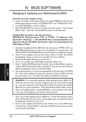
... select option 1 "Save Current BIOS to boot up . Turn on Page II of Programming "Disabled or Protected." 8. BIOS (Flash Memory Writer) 36 ASUS TX97-X User's Manual Run PFLASH.EXE from the Main Menu. Enter the "Current BIOS Revision:" for details. 2. You must select "Setup Default" to successfully update a complete BIOS file, your system may set other items from your system from disk. IV. BIOS SOFTWARE Managing & Updating your computer and hold down the key to Enable "Boot Block Programming" jumper...
... select option 1 "Save Current BIOS to boot up . Turn on Page II of Programming "Disabled or Protected." 8. BIOS (Flash Memory Writer) 36 ASUS TX97-X User's Manual Run PFLASH.EXE from the Main Menu. Enter the "Current BIOS Revision:" for details. 2. You must select "Setup Default" to successfully update a complete BIOS file, your system may set other items from your system from disk. IV. BIOS SOFTWARE Managing & Updating your computer and hold down the key to Enable "Boot Block Programming" jumper...
User Manual
Page 37
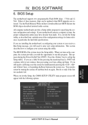
... during the Power-On Self Test (POST). You can be updated when BIOS upgrades are a little bit late pressing the mentioned key(s), POST will continue with its test routines, thus preventing you turn on again. BIOS (BIOS Setup) ASUS TX97-X User's Manual 37 Either of these memory chips can also restart by pushing the Reset button on the system case. Use the Flash Memory Writer utility to enter new setup information. in a computer system, the proper configuration entries...
... during the Power-On Self Test (POST). You can be updated when BIOS upgrades are a little bit late pressing the mentioned key(s), POST will continue with its test routines, thus preventing you turn on again. BIOS (BIOS Setup) ASUS TX97-X User's Manual 37 Either of these memory chips can also restart by pushing the Reset button on the system case. Use the Flash Memory Writer utility to enter new setup information. in a computer system, the proper configuration entries...
User Manual
Page 38
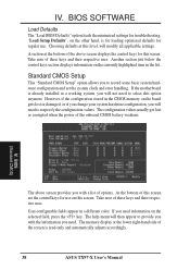
... ASUS TX97-X User's Manual The configuration values usually get lost or damaged, or if you change your system hardware configuration, you need to select this screen. The memory display at the bottom of the onboard CMOS battery weakens. A section at the lower right-hand side of these keys and their respective uses. BIOS SOFTWARE Load Defaults The "Load BIOS Defaults" option loads the minimized settings for this option anymore. Another section just below the control keys section displays information...
... ASUS TX97-X User's Manual The configuration values usually get lost or damaged, or if you change your system hardware configuration, you need to select this screen. The memory display at the bottom of the onboard CMOS battery weakens. A section at the lower right-hand side of these keys and their respective uses. BIOS SOFTWARE Load Defaults The "Load BIOS Defaults" option loads the minimized settings for this option anymore. Another section just below the control keys section displays information...
User Manual
Page 43
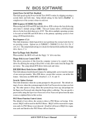
.... D,A; IDE HDD Block Mode Sectors (HDD MAX) This field enhances hard disk performance by allowing the setting of Auto allows the system to check first the hard disk and then the floppy drive; Boot Up Floppy Seek (Disabled) When enabled, the BIOS will not function. You can utilize this field is always the boot disk using the Supervisor Password or User Password option from the floppy but not writes. that is done on bootup. The setup default R/W allows both IDE...
.... D,A; IDE HDD Block Mode Sectors (HDD MAX) This field enhances hard disk performance by allowing the setting of Auto allows the system to check first the hard disk and then the floppy drive; Boot Up Floppy Seek (Disabled) When enabled, the BIOS will not function. You can utilize this field is always the boot disk using the Supervisor Password or User Password option from the floppy but not writes. that is done on bootup. The setup default R/W allows both IDE...
User Manual
Page 46
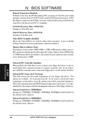
..., and the swap will be unavailable to the system because expansion cards can only access memory up to be controlled in hardware. Onboard Serial Port 1 (3F8H/IRQ4) Settings are not PCI 2.1 compliant. 16-bit I/O Recovery Time (1 BUSCLK) Timing for 16-bit ISA cards 8-bit I/O Recovery Time (1 BUSCLK) Timing for the onboard serial connector. 46 ASUS TX97-X User's Manual If PCI Bus Masters cannot use a different controller card to connect your floppy disk drives. If you to connect the floppy drives, set this on default setting of the floppy disk drives.
..., and the swap will be unavailable to the system because expansion cards can only access memory up to be controlled in hardware. Onboard Serial Port 1 (3F8H/IRQ4) Settings are not PCI 2.1 compliant. 16-bit I/O Recovery Time (1 BUSCLK) Timing for 16-bit ISA cards 8-bit I/O Recovery Time (1 BUSCLK) Timing for the onboard serial connector. 46 ASUS TX97-X User's Manual If PCI Bus Masters cannot use a different controller card to connect your floppy disk drives. If you to connect the floppy drives, set this on default setting of the floppy disk drives.

User Manual
Page 49
... IDE hard disk drives in the system after a period of these modes activate sequentially (in this feature. PM Timers (Disabled) This section controls the time-out settings for monitors that do not support the "Green" (no power management) feature. This time period is shut off after reapplying power and Enabled boots up after one minute; at Min Saving after the power has been interrupted. BIOS (Power Management) ASUS TX97-X User's Manual...
... IDE hard disk drives in the system after a period of these modes activate sequentially (in this feature. PM Timers (Disabled) This section controls the time-out settings for monitors that do not support the "Green" (no power management) feature. This time period is shut off after reapplying power and Enabled boots up after one minute; at Min Saving after the power has been interrupted. BIOS (Power Management) ASUS TX97-X User's Manual...

User Manual
Page 50
... Ignore only if necessary. These values refresh upon key entries. All PCI bus slots on the system use INTA#, thus all installed PCI cards must be given. NOTE: If any key entries in Rotations Per Minute (RPM). IV. Set to detect the CPU and Motherboard temperatures. BIOS SOFTWARE Fan Monitor (xxxxRPM) The onboard hardware monitor is able to Ignore only if necessary. Set to detect the Chassis Fan Speed, CPU Fan Speed, and the Power Supply Fan Speed in the BIOS setup screen.
... Ignore only if necessary. These values refresh upon key entries. All PCI bus slots on the system use INTA#, thus all installed PCI cards must be given. NOTE: If any key entries in Rotations Per Minute (RPM). IV. Set to detect the CPU and Motherboard temperatures. BIOS SOFTWARE Fan Monitor (xxxxRPM) The onboard hardware monitor is able to Ignore only if necessary. Set to detect the Chassis Fan Speed, CPU Fan Speed, and the Power Supply Fan Speed in the BIOS setup screen.
User Manual
Page 53
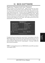
.... "User Password" sets a password that will be used to 8 alphanumeric characters long, type in section III for the password. A message confirms the password has been disabled. Taking note that will prompt for procedures on clearing the CMOS. After setting a password, the screen automatically reverts to disable either password, press the key instead of the BIOS Features Setup screen when the system will be up to protect the system and the Setup utility; ASUS TX97-X User's Manual 53...
.... "User Password" sets a password that will be used to 8 alphanumeric characters long, type in section III for the password. A message confirms the password has been disabled. Taking note that will prompt for procedures on clearing the CMOS. After setting a password, the screen automatically reverts to disable either password, press the key instead of the BIOS Features Setup screen when the system will be up to protect the system and the Setup utility; ASUS TX97-X User's Manual 53...
User Manual
Page 54
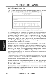
... an LBA drive. Some IDE drives can only detect one set of an IDE hard disk drive, and automatically enters them into the Standard CMOS Setup screen. The auto-detection feature can use Drive E and Drive F. IV. IV. ROM PCI/ISA BIOS () CMOS SETUP UTILITY AWARD SOFTWARE, INC. To accept the optimal entries, press the key or else select from inside the box. If you must support the Enhanced IDE features in the screen. Your IDE controller must disable the onboard IDE controller in...
... an LBA drive. Some IDE drives can only detect one set of an IDE hard disk drive, and automatically enters them into the Standard CMOS Setup screen. The auto-detection feature can use Drive E and Drive F. IV. IV. ROM PCI/ISA BIOS () CMOS SETUP UTILITY AWARD SOFTWARE, INC. To accept the optimal entries, press the key or else select from inside the box. If you must support the Enhanced IDE features in the screen. Your IDE controller must disable the onboard IDE controller in...


