User Manual
Page 4
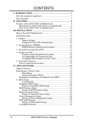
FEATURES 8 Features of the ASUS TX97-X Motherboard 8 Introduction to ASUS TX97 Series of motherboards 9 Parts of the ASUS Motherboard 12 Installation Steps 14 1. INSTALLATION 12 Map of the ASUS TX97-X Motherboard 11 III. BIOS SOFTWARE 34 Support Software 34 Flash Memory Writer Utility 34 Main Menu 34 Advanced Features Menu 35 Managing & Updating your Motherboard's BIOS 36 6. Jumpers 14...
FEATURES 8 Features of the ASUS TX97-X Motherboard 8 Introduction to ASUS TX97 Series of motherboards 9 Parts of the ASUS Motherboard 12 Installation Steps 14 1. INSTALLATION 12 Map of the ASUS TX97-X Motherboard 11 III. BIOS SOFTWARE 34 Support Software 34 Flash Memory Writer Utility 34 Main Menu 34 Advanced Features Menu 35 Managing & Updating your Motherboard's BIOS 36 6. Jumpers 14...
User Manual
Page 7
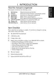
...BIOS supported Desktop Management Interface VI. DOS/Win3.1x: Audio Software Section (optional) Item Checklist Please check that your retailer. √ The ASUS TX97-X motherboard √ 1 IDE ribbon cable √ 1 floppy ribbon cable √ Support drivers and utilities as follows (view FILELIST.TXT ...for details) • LANDesk Client Manager (LDCM) Software • Flash Memory Writer utility to update the FLASH BIOS • Desktop Management Interface (DMI) utility • Audio drivers and utilities (optional) •...
...BIOS supported Desktop Management Interface VI. DOS/Win3.1x: Audio Software Section (optional) Item Checklist Please check that your retailer. √ The ASUS TX97-X motherboard √ 1 IDE ribbon cable √ 1 floppy ribbon cable √ Support drivers and utilities as follows (view FILELIST.TXT ...for details) • LANDesk Client Manager (LDCM) Software • Flash Memory Writer utility to update the FLASH BIOS • Desktop Management Interface (DMI) utility • Audio drivers and utilities (optional) •...
User Manual
Page 8
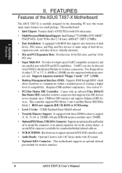
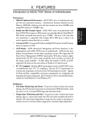
...Desktop Management Interface (DMI): Supports DMI through BIOS which allows hardware to communicate within a standard protocol creating a higher level of the ASUS TX97-X Motherboard The ASUS TX97-X is available for wireless connections. II. FEATURES Features of compatibility. (Requires DMI-enabled components.) (See section V) • PCI ...; Level 2 Cache: 512KB Pipelined Burst SRAM onboard. • Versatile Memory Support: Is equipped with three DIMM sockets to support (8, 16, 32, 64, or 128MB) 168-pin SDRAM memory modules up to make setup of hard drives, expansion cards, and other...
...Desktop Management Interface (DMI): Supports DMI through BIOS which allows hardware to communicate within a standard protocol creating a higher level of the ASUS TX97-X Motherboard The ASUS TX97-X is available for wireless connections. II. FEATURES Features of compatibility. (Requires DMI-enabled components.) (See section V) • PCI ...; Level 2 Cache: 512KB Pipelined Burst SRAM onboard. • Versatile Memory Support: Is equipped with three DIMM sockets to support (8, 16, 32, 64, or 128MB) 168-pin SDRAM memory modules up to make setup of hard drives, expansion cards, and other...
User Manual
Page 9
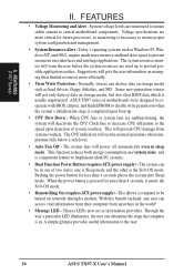
...system is no need to ASUS TX97 Series of motherboards sup- ASUS TX97 series of motherboards. ASUS TX97 series of motherboards Performance: • SDRAM Optimized Performance - FEATURES Introduction to upgrade current hard drives or cables. • Concurrent PCI - Synchronous Dynamic Random Access Memory (SDRAM) which can ... a safe heat level to 33MB/s. Both the BIOS and hardware levels of ASUS TX97 series of Windows 95 must be used. • PC '97 Compliant - port the new generation memory - To fully utilize the benefits of ACPI, an ACPIsupported OS such as ...
...system is no need to ASUS TX97 Series of motherboards sup- ASUS TX97 series of motherboards. ASUS TX97 series of motherboards Performance: • SDRAM Optimized Performance - FEATURES Introduction to upgrade current hard drives or cables. • Concurrent PCI - Synchronous Dynamic Random Access Memory (SDRAM) which can ... a safe heat level to 33MB/s. Both the BIOS and hardware levels of ASUS TX97 series of Windows 95 must be used. • PC '97 Compliant - port the new generation memory - To fully utilize the benefits of ACPI, an ACPIsupported OS such as ...
User Manual
Page 10
II. This will prevent CPU damage from their limited resources more memory and hard drive space to present enormous user interfaces and run large applications. FEATURES (TX97 Series) II. System voltage levels are used up . • CPU Slow Down - This function reduces both energy ... are monitored to ensure stable current to implement silent PC systems. • Dual Function Power Button (requires ATX power supply) - ASUS TX97 series of two states, one of motherboards were designed to cooperate with BIOS, chipset, and flash EPROM to ensure proper system configuration ...
II. This will prevent CPU damage from their limited resources more memory and hard drive space to present enormous user interfaces and run large applications. FEATURES (TX97 Series) II. System voltage levels are used up . • CPU Slow Down - This function reduces both energy ... are monitored to ensure stable current to implement silent PC systems. • Dual Function Power Button (requires ATX power supply) - ASUS TX97 series of two states, one of motherboards were designed to cooperate with BIOS, chipset, and flash EPROM to ensure proper system configuration ...

User Manual
Page 13
...:BUS Frequency Ratio p. 19 CPU Voltage Regulator Output Selection Expansion Slots 1) DIMM Sockets 2) CPU ZIF Socket 7 3) ISA Slots 4) PCI Slots p. 21 168-Pin DIMM Memory Expansion Sockets p. 23 Central Processing Unit (CPU) Socket p. 24 16-bit ISA Bus Expansion Slots p. 24 32-bit PCI Bus Expansion Slots Connectors 1) PS2KEYBOARD 2) PS2MOUSE...Lead (2-pins) p. 31 Keyboard Lock Switch Lead (5-pins) p. 31 Speaker Output Connector (4-pins) p. 32 Infrared Port Module Connector p. 32 Motherboard Power Connector (20-pin Block) ASUS TX97-X User's Manual 13 III. INSTALLATION (Map of Board) III.
...:BUS Frequency Ratio p. 19 CPU Voltage Regulator Output Selection Expansion Slots 1) DIMM Sockets 2) CPU ZIF Socket 7 3) ISA Slots 4) PCI Slots p. 21 168-Pin DIMM Memory Expansion Sockets p. 23 Central Processing Unit (CPU) Socket p. 24 16-bit ISA Bus Expansion Slots p. 24 32-bit PCI Bus Expansion Slots Connectors 1) PS2KEYBOARD 2) PS2MOUSE...Lead (2-pins) p. 31 Keyboard Lock Switch Lead (5-pins) p. 31 Speaker Output Connector (4-pins) p. 32 Infrared Port Module Connector p. 32 Motherboard Power Connector (20-pin Block) ASUS TX97-X User's Manual 13 III. INSTALLATION (Map of Board) III.
User Manual
Page 15
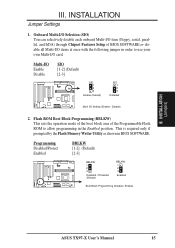
INSTALLATION Jumper Settings 1. This is required only if prompted by the Flash Memory Writer Utility as shown in the Enabled position. Flash ROM Boot Block Programming (BBLKW) This ...programming in BIOS SOFTWARE. Programming Disabled/Protect Enabled BBLKW [1-2] (Default) [2-3] BBLKW 1 2 3 Disabled / Protected (Default) BBLKW 1 2 3 Enabled Boot Block Programming (Disable / Enable) ASUS TX97-X User's Manual 15 Onboard Multi-I/O Selection (SIO) You can selectively disable each onboard Multi-I /O Setting (Enable / Disable) 2. Multi-I/O Enable Disable SIO [1-2] (Default) [2-3] SIO ...
INSTALLATION Jumper Settings 1. This is required only if prompted by the Flash Memory Writer Utility as shown in the Enabled position. Flash ROM Boot Block Programming (BBLKW) This ...programming in BIOS SOFTWARE. Programming Disabled/Protect Enabled BBLKW [1-2] (Default) [2-3] BBLKW 1 2 3 Disabled / Protected (Default) BBLKW 1 2 3 Enabled Boot Block Programming (Disable / Enable) ASUS TX97-X User's Manual 15 Onboard Multi-I/O Selection (SIO) You can selectively disable each onboard Multi-I /O Setting (Enable / Disable) 2. Multi-I/O Enable Disable SIO [1-2] (Default) [2-3] SIO ...

User Manual
Page 19
Voltage Regulator Output Selection (VID0, 1, 2) These jumpers set the voltage supplied to the CPU. III. INSTALLATION (System Memory) Intel P54C Pentium Intel P55C Pentium AMD-K5 Cyrix 6x86 166+ (75-200MHz) MMX (150-200MHz) (PR75-133MHz... 1 2 3 2.7Volt 1 2 3 2.8Volt 1 2 3 2.9Volt VID0 VID1 VID2 VID0 VID1 VID2 VID0 VID1 VID2 1 1 2 2 3 3 3.1Volt 3.4Volt Voltage Regulator Output Selection 1 2 3 3.5Volt R ASUS TX97-X User's Manual 19 INSTALLATION Compatible Cyrix CPU Identification The only Cyrix CPU that is supported on the underside of the CPU for the serial number...
Voltage Regulator Output Selection (VID0, 1, 2) These jumpers set the voltage supplied to the CPU. III. INSTALLATION (System Memory) Intel P54C Pentium Intel P55C Pentium AMD-K5 Cyrix 6x86 166+ (75-200MHz) MMX (150-200MHz) (PR75-133MHz... 1 2 3 2.7Volt 1 2 3 2.8Volt 1 2 3 2.9Volt VID0 VID1 VID2 VID0 VID1 VID2 VID0 VID1 VID2 1 1 2 2 3 3 3.1Volt 3.4Volt Voltage Regulator Output Selection 1 2 3 3.5Volt R ASUS TX97-X User's Manual 19 INSTALLATION Compatible Cyrix CPU Identification The only Cyrix CPU that is supported on the underside of the CPU for the serial number...
User Manual
Page 21
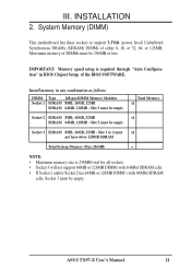
... have 64 or 128MB SDRAM Total System Memory (Max 256MB) = NOTE: • Maximum memory size is required through "Auto Configuration" in any combination as follows: DIMM Type 168-pin DIMM Memory Modules Socket 1 SDRAM 8MB, 16MB, 32MB SDRAM 64MB, 128MB - System Memory (DIMM) This motherboard has three sockets ...Setup of either 8, 16, or 32, 64, or 128MB. Slot 3 must be empty Total Memory x1 Socket 2 SDRAM 8MB, 16MB, 32MB x1 SDRAM 64MB, 128MB - ASUS TX97-X User's Manual 21 IMPORTANT: Memory speed setup is 256MB total for all sockets. • Socket 3 will not support 64MB or ...
... have 64 or 128MB SDRAM Total System Memory (Max 256MB) = NOTE: • Maximum memory size is required through "Auto Configuration" in any combination as follows: DIMM Type 168-pin DIMM Memory Modules Socket 1 SDRAM 8MB, 16MB, 32MB SDRAM 64MB, 128MB - System Memory (DIMM) This motherboard has three sockets ...Setup of either 8, 16, or 32, 64, or 128MB. Slot 3 must be empty Total Memory x1 Socket 2 SDRAM 8MB, 16MB, 32MB x1 SDRAM 64MB, 128MB - ASUS TX97-X User's Manual 21 IMPORTANT: Memory speed setup is 256MB total for all sockets. • Socket 3 will not support 64MB or ...
User Manual
Page 22
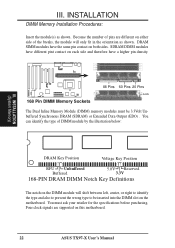
Because the number of pins are supported on both sides. SDRAM DIMM modules have the same pin contact on this motherboard. 22 ASUS TX97-X User's Manual You can identify the type of the breaks, the module will shift between left, center, or right to identify the type and also ... Reserved 3.3V 168-PIN DRAM DIMM Notch Key Definitions The notch on the DIMM module will only fit in the orientation as shown. INSTALLATION DIMM Memory Installation Procedures: Insert the module(s) as shown. You must be inserted into the DIMM slot on the motherboard. III.
Because the number of pins are supported on both sides. SDRAM DIMM modules have the same pin contact on this motherboard. 22 ASUS TX97-X User's Manual You can identify the type of the breaks, the module will shift between left, center, or right to identify the type and also ... Reserved 3.3V 168-PIN DRAM DIMM Notch Key Definitions The notch on the DIMM module will only fit in the orientation as shown. INSTALLATION DIMM Memory Installation Procedures: Insert the module(s) as shown. You must be inserted into the DIMM slot on the motherboard. III.
User Manual
Page 25
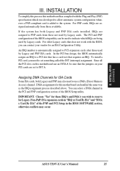
... automatic system configuration whenever a PNP-compliant card is automatically assigned to a PCI slot that the jumpers on your vendor for this motherboard use a DMA (Direct Memory Access) channel. Assigning DMA Channels for ISA Cards Some ISA cards, both Legacy and PNP ISA cards installed, IRQs are assigned to the system. IMPORTANT... cards are being used by Legacy cards. For PNP cards, IRQs are handled the same way as the IRQ assignment process described above. INSTALLATION (D(CMoAnCnhecatnonrsel)s) ASUS TX97-X User's Manual 25 III.
... automatic system configuration whenever a PNP-compliant card is automatically assigned to a PCI slot that the jumpers on your vendor for this motherboard use a DMA (Direct Memory Access) channel. Assigning DMA Channels for ISA Cards Some ISA cards, both Legacy and PNP ISA cards installed, IRQs are assigned to the system. IMPORTANT... cards are being used by Legacy cards. For PNP cards, IRQs are handled the same way as the IRQ assignment process described above. INSTALLATION (D(CMoAnCnhecatnonrsel)s) ASUS TX97-X User's Manual 25 III.
User Manual
Page 34
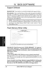
..." is operational. Create a bootable system floppy diskette by the Flash Memory Writer. BIOS (Flash Memory Writer) 34 ASUS TX97-X User's Manual PFLASH.EXE - Larger numbers represent a newer BIOS file. Flash Memory Writer Utility ASUSTeK PNP BIOS FLASH MEMORY WRITER V1.5 Copyright (C) 1995, ASUSTeK COMPUTER Inc. Main Menu ... of the following: 1. IV. To determine the BIOS version, check the last four numbers of the Flash memory chip onto a diskette. See "Flash Memory Writer Utility" in the Flash EPROM IMPORTANT: Flash Type may also be programmed by typing [FORMAT A:/S] from the...
..." is operational. Create a bootable system floppy diskette by the Flash Memory Writer. BIOS (Flash Memory Writer) 34 ASUS TX97-X User's Manual PFLASH.EXE - Larger numbers represent a newer BIOS file. Flash Memory Writer Utility ASUSTeK PNP BIOS FLASH MEMORY WRITER V1.5 Copyright (C) 1995, ASUSTeK COMPUTER Inc. Main Menu ... of the following: 1. IV. To determine the BIOS version, check the last four numbers of the Flash memory chip onto a diskette. See "Flash Memory Writer Utility" in the Flash EPROM IMPORTANT: Flash Type may also be programmed by typing [FORMAT A:/S] from the...
User Manual
Page 35
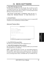
... old one of New BIOS is different. Please Use 'Advanced Feature' to File" option. SST 29EE010 Current BIOS Revision: #401A0-xxxx Choose one !!! BIOS (Flash Memory Writer) ASUS TX97-X User's Manual 35
... old one of New BIOS is different. Please Use 'Advanced Feature' to File" option. SST 29EE010 Current BIOS Revision: #401A0-xxxx Choose one !!! BIOS (Flash Memory Writer) ASUS TX97-X User's Manual 35
User Manual
Page 36
... . Create a bootable system floppy diskette by typing [FORMAT A:/S] from the Advanced Features Menu if prompted by the Flash Memory Writer. 1. Updating BIOS procedures (only when necessary): IMPORTANT: Flash type may not be "SST" or "INTEL." Enter...the original BIOS file you created above . Copy PFLASH.EXE to File." Boot from disk. If the Flash Memory Writer utility was not able to successfully update a complete BIOS file, your new diskette and select option 1 ... computer and open the system cabinet to disk above . 4. BIOS (Flash Memory Writer) 36 ASUS TX97-X User's Manual
... . Create a bootable system floppy diskette by typing [FORMAT A:/S] from the Advanced Features Menu if prompted by the Flash Memory Writer. 1. Updating BIOS procedures (only when necessary): IMPORTANT: Flash type may not be "SST" or "INTEL." Enter...the original BIOS file you created above . Copy PFLASH.EXE to File." Boot from disk. If the Flash Memory Writer utility was not able to successfully update a complete BIOS file, your new diskette and select option 1 ... computer and open the system cabinet to disk above . 4. BIOS (Flash Memory Writer) 36 ASUS TX97-X User's Manual
User Manual
Page 37
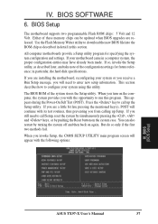
...system by simultaneously pressing the , and keys, or by turning the system off and then back on the system case. BIOS (BIOS Setup) ASUS TX97-X User's Manual 37 in particular, the hard disk specifications. Either of the system stores the Setup utility. You can be updated when BIOS ... Setup utility, as described in detail in a computer system, the proper configuration entries may have already been made. The BIOS ROM of these memory chips can also restart by pushing the Reset button on again. BIOS Setup The motherboard supports two programmable Flash ROM chips: 5 Volt and 12...
...system by simultaneously pressing the , and keys, or by turning the system off and then back on the system case. BIOS (BIOS Setup) ASUS TX97-X User's Manual 37 in particular, the hard disk specifications. Either of the system stores the Setup utility. You can be updated when BIOS ... Setup utility, as described in detail in a computer system, the proper configuration entries may have already been made. The BIOS ROM of these memory chips can also restart by pushing the Reset button on again. BIOS Setup The motherboard supports two programmable Flash ROM chips: 5 Volt and 12...
User Manual
Page 38
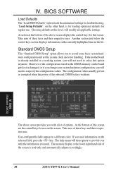
...the above screen provides you with the information you need. If the motherboard is already installed in the CMOS memory on the board gets lost or corrupted when the power of these keys and their respective uses. Take note... of options. The help menu will need to select this level, will not need information on this screen. The memory display at this option anymore. BIOS (Standard CMOS) The above screen displays the control keys for use . Standard CMOS... on the other hand, is read-only and automatically adjusts accordingly. 38 ASUS TX97-X User's Manual
...the above screen provides you with the information you need. If the motherboard is already installed in the CMOS memory on the board gets lost or corrupted when the power of these keys and their respective uses. Take note... of options. The help menu will need to select this level, will not need information on this screen. The memory display at this option anymore. BIOS (Standard CMOS) The above screen displays the control keys for use . Standard CMOS... on the other hand, is read-only and automatically adjusts accordingly. 38 ASUS TX97-X User's Manual

User Manual
Page 44
..., and 30. Typematic Rate Setting (Disabled) When Enabled, you need to Enable this option otherwise leave this on them specifically. OS/2 Onboard Memory > 64M (Disabled) When using OS/2 operating systems with ROMs on the setup default setting of color palette, wihile either the VGA or graphic...to the color palette and the other will need to know which the system registers repeated keystrokes. IV. BIOS (BIOS Features) 44 ASUS TX97-X User's Manual The setting Enabled should be to RAM enhances system performance, as graphics accelerators or MPEG Video Cards may not show ...
..., and 30. Typematic Rate Setting (Disabled) When Enabled, you need to Enable this option otherwise leave this on them specifically. OS/2 Onboard Memory > 64M (Disabled) When using OS/2 operating systems with ROMs on the setup default setting of color palette, wihile either the VGA or graphic...to the color palette and the other will need to know which the system registers repeated keystrokes. IV. BIOS (BIOS Features) 44 ASUS TX97-X User's Manual The setting Enabled should be to RAM enhances system performance, as graphics accelerators or MPEG Video Cards may not show ...
User Manual
Page 46
...Onboard Serial Port 2 (2F8H/IRQ3) Settings are 3F8H/IRQ4, 2F8H/IRQ3, 3E8H/IRQ4, 2E8H/IRQ10, and Disabled for the onboard serial connector. 46 ASUS TX97-X User's Manual IV. Onboard Serial Port 1 (3F8H/IRQ4) Settings are 3F8H/IRQ4, 2F8H/IRQ3, 3E8H/IRQ4, 2E8H/IRQ10, and Disabled for the... functionally the same as physically interchanging the connectors of 8-bit ISA cards which normally consume about 50-60 PCI Clocks without PCI delayed transaction. Memory from the BIOS Features floppy disk swap feature. Onboard FDC Swap A & B (No Swap) This field reverses the drive letter assignments of...
...Onboard Serial Port 2 (2F8H/IRQ3) Settings are 3F8H/IRQ4, 2F8H/IRQ3, 3E8H/IRQ4, 2E8H/IRQ10, and Disabled for the onboard serial connector. 46 ASUS TX97-X User's Manual IV. Onboard Serial Port 1 (3F8H/IRQ4) Settings are 3F8H/IRQ4, 2F8H/IRQ3, 3E8H/IRQ4, 2E8H/IRQ10, and Disabled for the... functionally the same as physically interchanging the connectors of 8-bit ISA cards which normally consume about 50-60 PCI Clocks without PCI delayed transaction. Memory from the BIOS Features floppy disk swap feature. Onboard FDC Swap A & B (No Swap) This field reverses the drive letter assignments of...
User Manual
Page 51
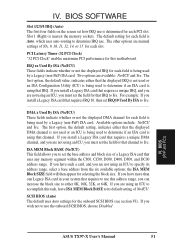
... channel for each PCI slot. The first option, the default setting, indicates either that IRQ to determine IRQ use the onboard SCSI BIOS, choose Disabled ASUS TX97-X User's Manual 51 the ISA MEM Block SIZE field will then appear for the onboard SCSI BIOS (see section VI). BIOS SOFTWARE Slot 1/2/3/4 IRQ (Auto... default setting of NA, 9, 10, 11, 12, 14, or 15 for that the displayed DMA channel is not used or an ICU is nearest the memory sockets. Slot 1 (Right) is being used by a Legacy (non-PnP) ISA card. Two options are manual settings of No/ICU. If you install a Legacy ISA...
... channel for each PCI slot. The first option, the default setting, indicates either that IRQ to determine IRQ use the onboard SCSI BIOS, choose Disabled ASUS TX97-X User's Manual 51 the ISA MEM Block SIZE field will then appear for the onboard SCSI BIOS (see section VI). BIOS SOFTWARE Slot 1/2/3/4 IRQ (Auto... default setting of NA, 9, 10, 11, 12, 14, or 15 for that the displayed DMA channel is not used or an ICU is nearest the memory sockets. Slot 1 (Right) is being used by a Legacy (non-PnP) ISA card. Two options are manual settings of No/ICU. If you install a Legacy ISA...
User Manual
Page 55
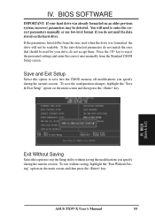
BIOS SOFTWARE IMPORTANT: If your drive, do not accept them. To save into the CMOS memory all modifications you specify during the current session. To exit without saving the modifications you specify during the current session. You will not be detected. ... Setup utility without saving, highlight the "Exit Without Saving" option on the main screen and then press the key. BIOS (Load Setup Defaults) IV. IV. ASUS TX97-X User's Manual 55 If the auto-detected parameters do not need the data stored on an older previous system, incorrect parameters may be readable. Press...
BIOS SOFTWARE IMPORTANT: If your drive, do not accept them. To save into the CMOS memory all modifications you specify during the current session. To exit without saving the modifications you specify during the current session. You will not be detected. ... Setup utility without saving, highlight the "Exit Without Saving" option on the main screen and then press the key. BIOS (Load Setup Defaults) IV. IV. ASUS TX97-X User's Manual 55 If the auto-detected parameters do not need the data stored on an older previous system, incorrect parameters may be readable. Press...


