
User Guide
Page 5
... PCI PnP 5-28 5.5 Power menu 5-30 5.5.1 ACPI APIC Support 5-30 5.5.2 APM Configuration 5-30 5.5.3 Hardware Monitor 5-32 5.6 Boot menu 5-33 5.6.1 Boot Device Priority 5-33 5.6.2 Boot Settings Configuration 5-34 5.6.3 Security 5-35 5.7 Exit menu 5-37 Chapter 6: RAID configuration and driver installation 6.1 RAID configurations 6-2 6.1.1 RAID definitions 6-2 6.1.2 Installing hard disk drives 6-3 6.1.3 Setting the RAID item in BIOS 6-3 6.1.4 Using the RAID configuration utility 6-3 6.1.5 Intel® Application Accelerator RAID Option ROM Utility 6-4 6.2 RAID driver installation...
... PCI PnP 5-28 5.5 Power menu 5-30 5.5.1 ACPI APIC Support 5-30 5.5.2 APM Configuration 5-30 5.5.3 Hardware Monitor 5-32 5.6 Boot menu 5-33 5.6.1 Boot Device Priority 5-33 5.6.2 Boot Settings Configuration 5-34 5.6.3 Security 5-35 5.7 Exit menu 5-37 Chapter 6: RAID configuration and driver installation 6.1 RAID configurations 6-2 6.1.1 RAID definitions 6-2 6.1.2 Installing hard disk drives 6-3 6.1.3 Setting the RAID item in BIOS 6-3 6.1.4 Using the RAID configuration utility 6-3 6.1.5 Intel® Application Accelerator RAID Option ROM Utility 6-4 6.2 RAID driver installation...
User Guide
Page 9
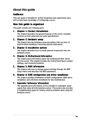
... information about the motherboard that you have to perform when installing or removing system components. 3. Chapter 5: BIOS information This chapter tells how to install optional components into the barebone server. 4 . Chapter 6: RAID configuration and driver installation This chapter provides information on front panel and rear panel specifications. 2. This section also provides a troubleshooting guide for this guide Audience This user guide is organized This guide contains the following parts: 1. Chapter 1: Product Introduction...
... information about the motherboard that you have to perform when installing or removing system components. 3. Chapter 5: BIOS information This chapter tells how to install optional components into the barebone server. 4 . Chapter 6: RAID configuration and driver installation This chapter provides information on front panel and rear panel specifications. 2. This section also provides a troubleshooting guide for this guide Audience This user guide is organized This guide contains the following parts: 1. Chapter 1: Product Introduction...
User Guide
Page 12
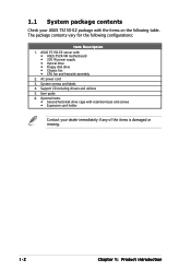
... hard disk drive cage with : • ASUS P5CR-VM motherboard • 300 W power supply • Optical drive • Floppy disk drive • Chassis fan • CPU fan and heatsink assembly 2. The package contents vary for the following table. AC power cord 3. Support CD including drivers and utilities 5. ASUS TS150-E2 server with retention base and screws • Expansion card holder Contact your ASUS TS150-E2 package with the items on the following configurations: Item Description 1. User guide 6. 1.1 System package contents Check...
... hard disk drive cage with : • ASUS P5CR-VM motherboard • 300 W power supply • Optical drive • Floppy disk drive • Chassis fan • CPU fan and heatsink assembly 2. The package contents vary for the following table. AC power cord 3. Support CD including drivers and utilities 5. ASUS TS150-E2 server with retention base and screws • Expansion card holder Contact your ASUS TS150-E2 package with the items on the following configurations: Item Description 1. User guide 6. 1.1 System package contents Check...
User Guide
Page 13
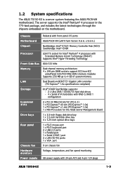
... port 2 x USB 2.0 ports 1 x Parallel port 1 x Serial (COM1) port 2 x LAN (RJ-45) ports 1 x VGA port 9 cm chassis fan Voltage, temperature, and fan speed monitoring SSI power supply with front panel I/O ports ASUS P5CR-VM (uATX form factor: 9.6 in. x 9.6 in the 775-land package, and includes the latest technologies through the chipsets embedded on the motherboard. Chassis Motherboard Chipset Processor Front Side Bus Memory LAN Storage Expansion slots Drive bays Rear panel Chassis fan Hardware monitors Power supply Pedestal with 24-pin ATX and 4-pin 12V plugs ASUS TS150-E2 1-3 1.2 System...
... port 2 x USB 2.0 ports 1 x Parallel port 1 x Serial (COM1) port 2 x LAN (RJ-45) ports 1 x VGA port 9 cm chassis fan Voltage, temperature, and fan speed monitoring SSI power supply with front panel I/O ports ASUS P5CR-VM (uATX form factor: 9.6 in. x 9.6 in the 775-land package, and includes the latest technologies through the chipsets embedded on the motherboard. Chassis Motherboard Chipset Processor Front Side Bus Memory LAN Storage Expansion slots Drive bays Rear panel Chassis fan Hardware monitors Power supply Pedestal with 24-pin ATX and 4-pin 12V plugs ASUS TS150-E2 1-3 1.2 System...
User Guide
Page 23
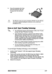
... damaging the CPU! Install an Intel® Pentium® 4 CPU that the item Hyper-Threading Technology is supported under Windows® 2000 Advanced Server, Windows® 2003 Server, and Linux 2.4.x (kernel) and later versions only. Power up the system and enter the BIOS Setup (see Chapter 5: BIOS setup). To use the Hyper-Threading compiler to Enabled. ASUS TS150-E2 2-7 If you installed a CPU that supports Hyper-Threading Technology. 3. Reboot the computer. Under Linux, use the Hyper...
... damaging the CPU! Install an Intel® Pentium® 4 CPU that the item Hyper-Threading Technology is supported under Windows® 2000 Advanced Server, Windows® 2003 Server, and Linux 2.4.x (kernel) and later versions only. Power up the system and enter the BIOS Setup (see Chapter 5: BIOS setup). To use the Hyper-Threading compiler to Enabled. ASUS TS150-E2 2-7 If you installed a CPU that supports Hyper-Threading Technology. 3. Reboot the computer. Under Linux, use the Hyper...
User Guide
Page 60
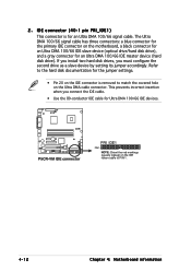
... install two hard disk drives, you connect the IDE cable. • Use the 80-conductor IDE cable for the jumper settings. • Pin 20 on the IDE connector is for an Ultra DMA 100/66 IDE master device (hard disk drive). This prevents incorrect insertion when you must configure the second drive as a slave device by setting its jumper accordingly. IDE connector (40-1 pin PRI_IDE1) This connector is removed to PIN 1. 4-12 Chapter 4: Motherboard...
... install two hard disk drives, you connect the IDE cable. • Use the 80-conductor IDE cable for the jumper settings. • Pin 20 on the IDE connector is for an Ultra DMA 100/66 IDE master device (hard disk drive). This prevents incorrect insertion when you must configure the second drive as a slave device by setting its jumper accordingly. IDE connector (40-1 pin PRI_IDE1) This connector is removed to PIN 1. 4-12 Chapter 4: Motherboard...
User Guide
Page 61
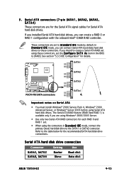
... Advanced Server, or Windows® Server 2003 before using Windows® 2000/2003 Server. • Use only two Serial ATA RAID connectors for the recommended SATA hard disk drive connections. Serial ATA hard disk drive connection Connector Setting Use SATA1, SATA2 SATA3, SATA4 Master Slave Boot disk Data disk ASUS TS150-E2 4-13 Serial ATA connectors (7-pin SATA1, SATA2, SATA3, SATA4) These connectors are for the Serial ATA signal cables for details. These connectors are using Serial ATA hard disk drives. If you can create a RAID 0 or RAID 1 configuration with the...
... Advanced Server, or Windows® Server 2003 before using Windows® 2000/2003 Server. • Use only two Serial ATA RAID connectors for the recommended SATA hard disk drive connections. Serial ATA hard disk drive connection Connector Setting Use SATA1, SATA2 SATA3, SATA4 Master Slave Boot disk Data disk ASUS TS150-E2 4-13 Serial ATA connectors (7-pin SATA1, SATA2, SATA3, SATA4) These connectors are for the Serial ATA signal cables for details. These connectors are using Serial ATA hard disk drives. If you can create a RAID 0 or RAID 1 configuration with the...
User Guide
Page 86
..., and SMART monitoring). These values are specifically configuring a CD-ROM drive. These items show "Not Detected" if no IDE device is a separate sub-menu for each IDE device. Select CDROM if you are not user-configurable. When set to Auto, the data transfer from and to Auto enables the LBA mode if the device supports this mode, and if the device was not previously formatted with LBA mode disabled. Select a device item then...
..., and SMART monitoring). These values are specifically configuring a CD-ROM drive. These items show "Not Detected" if no IDE device is a separate sub-menu for each IDE device. Select CDROM if you are not user-configurable. When set to Auto, the data transfer from and to Auto enables the LBA mode if the device supports this mode, and if the device was not previously formatted with LBA mode disabled. Select a device item then...
User Guide
Page 92
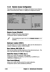
...is enabled. Configure Remote Access type and parameters Remote Access [Disabled] Serial port number Base Address, IRQ Serial Port Mode Flow Control Redirection after BIOS POST Terminal Type VT-UTF8 Combo Key Support Sredir Memory Display Delay [COM1] [3F8h, 4] [115200, 8,n,1] [None] [Always] [ANSI] [Enabled] [No Delay] Select Remote Access type. This item is auto-detected and is not user-configurable. Select an item then press to display the configuration options. Configuration options: [None [Hardware] [Software] 5-22 Chapter 5: Motherboard information Configuration options...
...is enabled. Configure Remote Access type and parameters Remote Access [Disabled] Serial port number Base Address, IRQ Serial Port Mode Flow Control Redirection after BIOS POST Terminal Type VT-UTF8 Combo Key Support Sredir Memory Display Delay [COM1] [3F8h, 4] [115200, 8,n,1] [None] [Always] [ANSI] [Enabled] [No Delay] Select Remote Access type. This item is auto-detected and is not user-configurable. Select an item then press to display the configuration options. Configuration options: [None [Hardware] [Software] 5-22 Chapter 5: Motherboard information Configuration options...
User Guide
Page 94
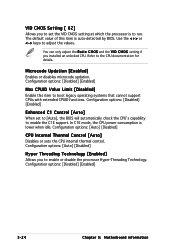
.... The default value of this item to the CPU documentation for details. Refer to boot legacy operating systems that cannot support CPUs with extended CPUID functions. In C1E mode, the CPU power consumption is auto-detected by BIOS. Configuration options: [Auto] [Disabled] Hyper Threading Technology [Enabled] Allows you to run. Configuration options: [Disabled] [Enabled] 5-24 Chapter 5: Motherboard information VID CMOS Setting [ 62] Allows you to set to [Auto], the BIOS will automatically check the CPU's capability...
.... The default value of this item to the CPU documentation for details. Refer to boot legacy operating systems that cannot support CPUs with extended CPUID functions. In C1E mode, the CPU power consumption is auto-detected by BIOS. Configuration options: [Auto] [Disabled] Hyper Threading Technology [Enabled] Allows you to run. Configuration options: [Disabled] [Enabled] 5-24 Chapter 5: Motherboard information VID CMOS Setting [ 62] Allows you to set to [Auto], the BIOS will automatically check the CPU's capability...
User Guide
Page 100
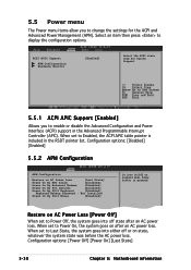
... into On/Off or Suspend when Power button is included in the Advanced Programmable Interrupt Controller (APIC). Configuration options: [Disabled] [Enabled] 5.5.2 APM Configuration APM Configuration Restore on state, whatever the system state was before the AC power loss. Configuration options: [Power Off] [Power On] [Last State] 5-30 Chapter 5: Motherboard information ACPI APIC Support APM Configuration Hardware Monitor [Enabled] Select the ACPI state used for the ACPI and Advanced Power Management (APM).
... into On/Off or Suspend when Power button is included in the Advanced Programmable Interrupt Controller (APIC). Configuration options: [Disabled] [Enabled] 5.5.2 APM Configuration APM Configuration Restore on state, whatever the system state was before the AC power loss. Configuration options: [Power Off] [Power On] [Last State] 5-30 Chapter 5: Motherboard information ACPI APIC Support APM Configuration Hardware Monitor [Enabled] Select the ACPI state used for the ACPI and Advanced Power Management (APM).
User Guide
Page 105
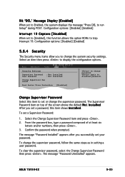
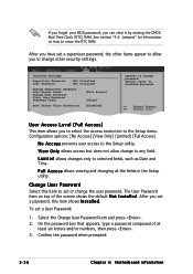
... the default N o t I n s t a l l e d. To change password. ASUS TS150-E2 5-35 again to set to [Enabled], this item shows I n s t a l l e d. The Supervisor Password item on top of at least six letters and/or numbers, then press . 3. To set to Enabled, the system displays the message "Press DEL to run Setup" during POST. The message "Password Uninstalled" appears. Select an item then press to trap Interrupt 19. Configuration options: [Disabled] [Enabled] Interrupt 19 Capture [Disabled] When set or change...
... the default N o t I n s t a l l e d. To change password. ASUS TS150-E2 5-35 again to set to [Enabled], this item shows I n s t a l l e d. The Supervisor Password item on top of at least six letters and/or numbers, then press . 3. To set to Enabled, the system displays the message "Press DEL to run Setup" during POST. The message "Password Uninstalled" appears. Select an item then press to trap Interrupt 19. Configuration options: [Disabled] [Enabled] Interrupt 19 Capture [Disabled] When set or change...
User Guide
Page 106
... access to the Setup utility. If you forget your BIOS password, you to change other items appear to allow change to any field. V i e w O n l y allows access but does not allow you can clear it by erasing the CMOS Real Time Clock (RTC) RAM. Confirm the password when prompted. 5-36 Chapter 5: Motherboard information Security Settings Supervisor Password : Not Installed User Password : Not Installed Change Supervisor Password User Access Level Change User Password Clear User Password Password Check [Full Access] [Setup] Boot Sector Virus Protection [Disabled] to change password...
... access to the Setup utility. If you forget your BIOS password, you to change other items appear to allow change to any field. V i e w O n l y allows access but does not allow you can clear it by erasing the CMOS Real Time Clock (RTC) RAM. Confirm the password when prompted. 5-36 Chapter 5: Motherboard information Security Settings Supervisor Password : Not Installed User Password : Not Installed Change Supervisor Password User Access Level Change User Password Clear User Password Password Check [Full Access] [Setup] Boot Sector Virus Protection [Disabled] to change password...
User Guide
Page 110
...; Matrix Storage technology supported by the ICH6R chip allows you want to boot the system from a hard disk drive included in a created RAID set, copy first the RAID driver from one drive fails, the disk array management software directs all applications to change the hard disk drive partition size without losing any advantage over using only two identical hard disk drives. Refer to the entire system. Refer to the selected hard disk drive. Use of the data in parallel...
...; Matrix Storage technology supported by the ICH6R chip allows you want to boot the system from a hard disk drive included in a created RAID set, copy first the RAID driver from one drive fails, the disk array management software directs all applications to change the hard disk drive partition size without losing any advantage over using only two identical hard disk drives. Refer to the entire system. Refer to the selected hard disk drive. Use of the data in parallel...
User Guide
Page 111
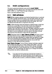
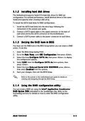
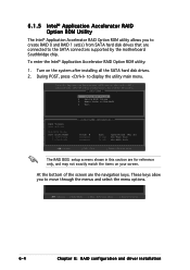
...the BIOS Setup during POST. 2. Refer to the succeeding sections for details on entering and navigating through the BIOS Setup. 6.1.4 Using the RAID configuration utility You can create a RAID set(s). To install the SATA hard disks for details on how to the Main Menu, select IDE Configuration, then press . 3. Select the item O n b o a r d S e r i a l - 6.1.2 Installing hard disk drives The motherboard supports Serial ATA hard disk drives for RAID set using the I n t e l® A p p l i c a t i o n A c c e l e r a t o r R A I D from the options. 6. ASUS TS150-E2 6-3 For...
...the BIOS Setup during POST. 2. Refer to the succeeding sections for details on entering and navigating through the BIOS Setup. 6.1.4 Using the RAID configuration utility You can create a RAID set(s). To install the SATA hard disks for details on how to the Main Menu, select IDE Configuration, then press . 3. Select the item O n b o a r d S e r i a l - 6.1.2 Installing hard disk drives The motherboard supports Serial ATA hard disk drives for RAID set using the I n t e l® A p p l i c a t i o n A c c e l e r a t o r R A I D from the options. 6. ASUS TS150-E2 6-3 For...
User Guide
Page 112
... the bottom of the screen are connected to the SATA connectors supported by the motherboard Southbridge chip. These keys allow you to create RAID 0 and RAID 1 set(s) from SATA hard disk drives that are the navigation keys. Non-RAID Disks: Port Drive Model 0 ST380013AS 1 ST380013AS [ DISK/VOLUME INFORMATION ] Serial # xxxxxxxx xxxxxxxx Size 74.5GB 74.5GB Type/Status (Vol ID) Non-RAID Disk Non-RAID Disk [ ]-Select [ESC] Exit [Enter]-Select Menu The RAID BIOS setup screens shown in this section...
... the bottom of the screen are connected to the SATA connectors supported by the motherboard Southbridge chip. These keys allow you to create RAID 0 and RAID 1 set(s) from SATA hard disk drives that are the navigation keys. Non-RAID Disks: Port Drive Model 0 ST380013AS 1 ST380013AS [ DISK/VOLUME INFORMATION ] Serial # xxxxxxxx xxxxxxxx Size 74.5GB 74.5GB Type/Status (Vol ID) Non-RAID Disk Non-RAID Disk [ ]-Select [ESC] Exit [Enter]-Select Menu The RAID BIOS setup screens shown in this section...
User Guide
Page 116
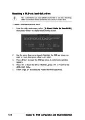
... 2. A confirmation window appears. 4. Resetting a RAID volume HDD deletes all data on the drive. Press to select and reset other RAID set drives. 6-8 Chapter 6: RAID configuration and driver installation Follow steps 2-4 to reset the RAID set drive. Resetting a RAID set hard disks drive Take caution before you want to reset, then press to non-RAID. To reset a RAID set drive you reset a RAID volume HDD to select. 3. Use the up or down arrow keys to highlight the RAID set hard disk drive: 1. otherwise, press to return to the utility main menu. 5.
... 2. A confirmation window appears. 4. Resetting a RAID volume HDD deletes all data on the drive. Press to select and reset other RAID set drives. 6-8 Chapter 6: RAID configuration and driver installation Follow steps 2-4 to reset the RAID set drive. Resetting a RAID set hard disks drive Take caution before you want to reset, then press to non-RAID. To reset a RAID set drive you reset a RAID volume HDD to select. 3. Use the up or down arrow keys to highlight the RAID set hard disk drive: 1. otherwise, press to return to the utility main menu. 5.
User Guide
Page 118
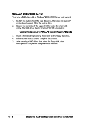
... the floppy disk drive. 4. After creating a RAID driver disk, eject the floppy disk, then write-protect it to locate the driver disk utility. Browse the contents of the support CD to prevent computer virus infection. 6-10 Chapter 6: RAID configuration and driver installation Windows® 2000/2003 Server To create a RAID driver disk in : \Drivers\Chipset\Intel\IAA\F6 Install Floppy\F6flpy32 3. Restart the system from the hard disk drive, then place the system/ motherboard support CD in...
... the floppy disk drive. 4. After creating a RAID driver disk, eject the floppy disk, then write-protect it to locate the driver disk utility. Browse the contents of the support CD to prevent computer virus infection. 6-10 Chapter 6: RAID configuration and driver installation Windows® 2000/2003 Server To create a RAID driver disk in : \Drivers\Chipset\Intel\IAA\F6 Install Floppy\F6flpy32 3. Restart the system from the hard disk drive, then place the system/ motherboard support CD in...
User Guide
Page 120
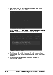
When prompted, press to the floppy disk drive, then press . 5. Insert the Intel® ICH6R RAID driver disk you created earlier to continue installation. 7. Setup then proceeds with the OS installation. Select the I n t e l ( R ) 8 2 8 0 1 F R S A T A R A I D C o n t r o l l e r ( D e s k t o p I C H 6 R ) from the RAID driver disk. Follow screen instructions to select. 6. The Windows® 2000/2003 Setup loads the RAID controller drivers from the options, then press to continue. 6-12 Chapter 6: RAID configuration and driver installation 4.
When prompted, press to the floppy disk drive, then press . 5. Insert the Intel® ICH6R RAID driver disk you created earlier to continue installation. 7. Setup then proceeds with the OS installation. Select the I n t e l ( R ) 8 2 8 0 1 F R S A T A R A I D C o n t r o l l e r ( D e s k t o p I C H 6 R ) from the RAID driver disk. Follow screen instructions to select. 6. The Windows® 2000/2003 Setup loads the RAID controller drivers from the options, then press to continue. 6-12 Chapter 6: RAID configuration and driver installation 4.
User Guide
Page 130
There is no need to install an additional driver(s) to support the onboard VGA. 6-22 Chapter 6: RAID configuration and driver installation 6.4.3 Red Hat® Linux 9.0 The Red Hat® Linux 9.0 (2.4.x kernels) operating system automatically recognizes the Intel® E7221 SVGA driver during system installation.
There is no need to install an additional driver(s) to support the onboard VGA. 6-22 Chapter 6: RAID configuration and driver installation 6.4.3 Red Hat® Linux 9.0 The Red Hat® Linux 9.0 (2.4.x kernels) operating system automatically recognizes the Intel® E7221 SVGA driver during system installation.


