T2-P User Manual
Page 3
... Internal components 20 1.6 LED panel 21 Chapter 2: Basic installation 2.1 Preparation 24 2.2 Before you proceed 24 2.3 Removing the cover 25 2.4 Removing the power supply 26 2.5 Installing a CPU 27 2.5.1 Removing the CPU fan and heatsink assembly .... 27 2.5.2 CPU installation 28 2.5.3 Re-installing the CPU fan and heatsink... card 34 2.8 Installing a second optical drive 35 2.9 Installing a hard disk drive (HDD 37 2.10 Re-installing the power supply unit 39 2.11 Replacing the cover 41 2.12 Connecting external devices 42 Chapter 3: Starting up 3.1 Installing an operating system 46...
... Internal components 20 1.6 LED panel 21 Chapter 2: Basic installation 2.1 Preparation 24 2.2 Before you proceed 24 2.3 Removing the cover 25 2.4 Removing the power supply 26 2.5 Installing a CPU 27 2.5.1 Removing the CPU fan and heatsink assembly .... 27 2.5.2 CPU installation 28 2.5.3 Re-installing the CPU fan and heatsink... card 34 2.8 Installing a second optical drive 35 2.9 Installing a hard disk drive (HDD 37 2.10 Re-installing the power supply unit 39 2.11 Replacing the cover 41 2.12 Connecting external devices 42 Chapter 3: Starting up 3.1 Installing an operating system 46...
T2-P User Manual
Page 5
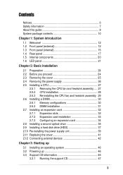
... 104 5.4.2 Chipset 105 5.4.3 Onboard Devices Configuration 108 5.4.4 PCI PnP 110 5.4.5 USB Configuration 112 5.4.6 Instant Music Configuration 114 5.5 Power menu 115 5.5.1 Suspend Mode [Auto 115 5.5.2 Repost Video on S3 Resume [No 115 5.5.3 ACPI 2.0 Support [No 115 5.5.4... menu 119 5.6.2 Removable Drives 120 5.6.3 CDROM Drives 120 5.6.4 Boot Settings Configuration 121 5.6.5 Security 123 5.7 Exit menu 125 Appendix A.1 Power supply specifications A-2 A.2 Wireless LAN adapter channels A-3 5 Contents 5.2.5 Sub-menu items 99 5.2.6 Configuration fields 99 5.2.7 Pop-up window 99...
... 104 5.4.2 Chipset 105 5.4.3 Onboard Devices Configuration 108 5.4.4 PCI PnP 110 5.4.5 USB Configuration 112 5.4.6 Instant Music Configuration 114 5.5 Power menu 115 5.5.1 Suspend Mode [Auto 115 5.5.2 Repost Video on S3 Resume [No 115 5.5.3 ACPI 2.0 Support [No 115 5.5.4... menu 119 5.6.2 Removable Drives 120 5.6.3 CDROM Drives 120 5.6.4 Boot Settings Configuration 121 5.6.5 Security 123 5.7 Exit menu 125 Appendix A.1 Power supply specifications A-2 A.2 Wireless LAN adapter channels A-3 5 Contents 5.2.5 Sub-menu items 99 5.2.6 Configuration fields 99 5.2.7 Pop-up window 99...

T2-P User Manual
Page 7
... it may become wet. Operation safety • Before installing devices into the system, carefully read all cables are correctly connected and the power cables are connected. • If the power supply is incorrectly replaced. Do not place the product in any damage, contact your dealer immediately. • To avoid short circuits, keep paper...
... it may become wet. Operation safety • Before installing devices into the system, carefully read all cables are correctly connected and the power cables are connected. • If the power supply is incorrectly replaced. Do not place the product in any damage, contact your dealer immediately. • To avoid short circuits, keep paper...
T2-P User Manual
Page 8
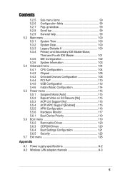
...System introduction This chapter gives a general description of personal computers. Chapter 4: Motherboard information This chapter gives information about the ASUS Terminator 2 barebone system. Safeguards About this guide is intended for the wireless LAN adapter (available only on systems with ... Chapter 3: Starting up This chapter helps you power up the system and install drivers and utilities from the support CD. 4. This guide is organized This guide contains the following parts: 1. Appendix The Appendix includes the power supply unit specification and IEEE 802.11b channels for ...
...System introduction This chapter gives a general description of personal computers. Chapter 4: Motherboard information This chapter gives information about the ASUS Terminator 2 barebone system. Safeguards About this guide is intended for the wireless LAN adapter (available only on systems with ... Chapter 3: Starting up This chapter helps you power up the system and install drivers and utilities from the support CD. 4. This guide is organized This guide contains the following parts: 1. Appendix The Appendix includes the power supply unit specification and IEEE 802.11b channels for ...
T2-P User Manual
Page 18
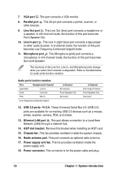
... port allows connection to the table below for audio ports function variation. Chassis fan. This fan provides ventilation inside the power supply unit. 18. Radio antenna port. Power connector. This connector is for connecting USB 2.0 devices such as a mouse, printer, scanner, camera, PDA, and ...others. 13. Line Out port . The functions of this bracket when installing an AGP card. 15. Power supply unit fan. In 6-channel mode, the function of this port becomes Low Frequency Enhanced Output/Center. 11. This Microphone (pink) port connects ...
... port allows connection to the table below for audio ports function variation. Chassis fan. This fan provides ventilation inside the power supply unit. 18. Radio antenna port. Power connector. This connector is for connecting USB 2.0 devices such as a mouse, printer, scanner, camera, PDA, and ...others. 13. Line Out port . The functions of this bracket when installing an AGP card. 15. Power supply unit fan. In 6-channel mode, the function of this port becomes Low Frequency Enhanced Output/Center. 11. This Microphone (pink) port connects ...
T2-P User Manual
Page 20
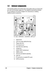
ASUS P4P8T motherboard 8. The installed components are labeled for instructions on installing additional system components. 1 6 3 2 9 8 7 4 5 10 11 12 1. Floppy disk drive 4. Proceed to Chapter 2 for your ... an installed PCI card) 12. 1.5 Internal components The illustration below is the internal view of the system when you remove the top cover and the power supply unit. Front panel cover 5.
ASUS P4P8T motherboard 8. The installed components are labeled for instructions on installing additional system components. 1 6 3 2 9 8 7 4 5 10 11 12 1. Floppy disk drive 4. Proceed to Chapter 2 for your ... an installed PCI card) 12. 1.5 Internal components The illustration below is the internal view of the system when you remove the top cover and the power supply unit. Front panel cover 5.
T2-P User Manual
Page 24
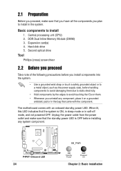
... install components into the system. • Use a grounded wrist strap or touch a safely grounded object or to a metal object, such as the power supply case, before installing any component, place it on a grounded antistatic pad or in the bag that came with an onboard standby... before handling components to avoid damaging them . • Whenever you uninstall any system component. 2.1 Preparation Before you proceed, make sure that the standby power LED is ON, in sleep mode or in the system. Hard disk drive 5. The motherboard comes with the component. P4P8T ® P4P8T Onboard LED...
... install components into the system. • Use a grounded wrist strap or touch a safely grounded object or to a metal object, such as the power supply case, before installing any component, place it on a grounded antistatic pad or in the bag that came with an onboard standby... before handling components to avoid damaging them . • Whenever you uninstall any system component. 2.1 Preparation Before you proceed, make sure that the standby power LED is ON, in sleep mode or in the system. Hard disk drive 5. The motherboard comes with the component. P4P8T ® P4P8T Onboard LED...
T2-P User Manual
Page 26
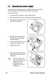
... 1. Lay the system on its side on the motherboard, then set the PSU aside. Disconnect the power plugs on a flat, stable surface. 2. Disconnect the optical drive and floppy disk drive power plugs. 3. Push the PSU towards the front 4 6 panel for about half an inch. 6. ...7. When removing the PSU, 7 make sure to the left until the side hook is disengaged from the chassis. 5. 2.4 Removing the power supply You must remove the power supply unit (PSU) before you can install a central processing unit (CPU) and other system 7 components. 26 Chapter 2: Basic installation Remove the...
... 1. Lay the system on its side on the motherboard, then set the PSU aside. Disconnect the power plugs on a flat, stable surface. 2. Disconnect the optical drive and floppy disk drive power plugs. 3. Push the PSU towards the front 4 6 panel for about half an inch. 6. ...7. When removing the PSU, 7 make sure to the left until the side hook is disengaged from the chassis. 5. 2.4 Removing the power supply You must remove the power supply unit (PSU) before you can install a central processing unit (CPU) and other system 7 components. 26 Chapter 2: Basic installation Remove the...
T2-P User Manual
Page 36
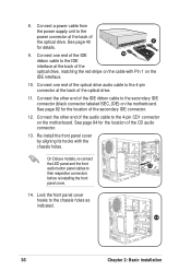
Connect a power cable from the power supply unit to the power connector at the back of the CD audio connector. 13. See page 84 for the location of the optical drive. Connect one end of the ...
Connect a power cable from the power supply unit to the power connector at the back of the CD audio connector. 13. See page 84 for the location of the optical drive. Connect one end of the ...
T2-P User Manual
Page 38
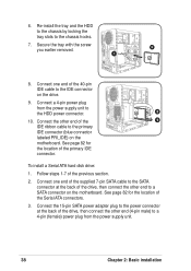
... 2: Basic installation Follow steps 1-7 of the 40-pin IDE cable to a 4-pin (female) power plug from the power supply unit to the chassis hooks. 7. 6. Connect the 15-pin SATA power adapter plug to the power connector at the back of the Serial ATA connectors. 3. Secure the tray with the screw 6 you...9. Connect one end of the supplied 7-pin SATA cable to the SATA connector at the back of the primary IDE connector. Connect one end of the previous section. 2. Re-install the tray and the HDD to the chassis by locking the tray slots to the HDD power connector. 8 10.
... 2: Basic installation Follow steps 1-7 of the 40-pin IDE cable to a 4-pin (female) power plug from the power supply unit to the chassis hooks. 7. 6. Connect the 15-pin SATA power adapter plug to the power connector at the back of the Serial ATA connectors. 3. Secure the tray with the screw 6 you...9. Connect one end of the supplied 7-pin SATA cable to the SATA connector at the back of the primary IDE connector. Connect one end of the previous section. 2. Re-install the tray and the HDD to the chassis by locking the tray slots to the HDD power connector. 8 10.
T2-P User Manual
Page 39
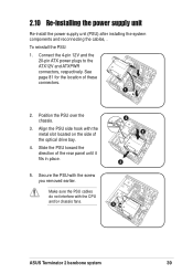
...ASUS Terminator 2 barebone system 39 See page 81 for the location of the rear panel until it fits in place. 3 2 4 5. Slide the PSU toward the direction of these connectors. 1 2. Connect the 4-pin 12V and the 20-pin ATX power plugs to the ATX12V and ATXPWR connectors, respectively. 2.10 Re-installing the power supply... unit Re-install the power supply unit (PSU) after installing the system components and reconnecting the cables,...
...ASUS Terminator 2 barebone system 39 See page 81 for the location of the rear panel until it fits in place. 3 2 4 5. Slide the PSU toward the direction of these connectors. 1 2. Connect the 4-pin 12V and the 20-pin ATX power plugs to the ATX12V and ATXPWR connectors, respectively. 2.10 Re-installing the power supply... unit Re-install the power supply unit (PSU) after installing the system components and reconnecting the cables,...

T2-P User Manual
Page 40
... damage the system! 230 40 Chapter 2: Basic installation 7 8 Power supply unit plugs 1 1 6 6. See the Appendix for the power supply specifications. Setting the switch to the power connector of the hard disk drive. Connect the 4-pin power plug to 115V in your area. Connect the 4-pin power plug to the power connector of the floppy disk drive. 7. Voltage selector...
... damage the system! 230 40 Chapter 2: Basic installation 7 8 Power supply unit plugs 1 1 6 6. See the Appendix for the power supply specifications. Setting the switch to the power connector of the hard disk drive. Connect the 4-pin power plug to 115V in your area. Connect the 4-pin power plug to the power connector of the floppy disk drive. 7. Voltage selector...

T2-P User Manual
Page 81
... Ground +3.3 Volts +3.3 Volts +5.0 Volts +5.0 Volts -5.0 Volts Ground Ground Ground Power Supply On Ground -12.0Volts +3.3Volts P4P8T ® P4P8T ATX Power Connector ATX12V +12V DC COM +12V DC COM ASUS Terminator 2 barebone system 81 These are for the 20-pin and 4-pin power plugs from the power supply unit are designed to fit these connectors in only...
... Ground +3.3 Volts +3.3 Volts +5.0 Volts +5.0 Volts -5.0 Volts Ground Ground Ground Power Supply On Ground -12.0Volts +3.3Volts P4P8T ® P4P8T ATX Power Connector ATX12V +12V DC COM +12V DC COM ASUS Terminator 2 barebone system 81 These are for the 20-pin and 4-pin power plugs from the power supply unit are designed to fit these connectors in only...

T2-P User Manual
Page 85
... in the ON mode for more than 4 seconds turns the system OFF. • IDE LED Lead This 2-pin connector supplies power to light up when you turn on the BIOS or OS settings. ASUS Terminator 2 barebone system 85 System panel connector (8-1 pin PANEL) This connector accommodates several system front panel functions. 13. The...
... in the ON mode for more than 4 seconds turns the system OFF. • IDE LED Lead This 2-pin connector supplies power to light up when you turn on the BIOS or OS settings. ASUS Terminator 2 barebone system 85 System panel connector (8-1 pin PANEL) This connector accommodates several system front panel functions. 13. The...
T2-P User Manual
Page 116
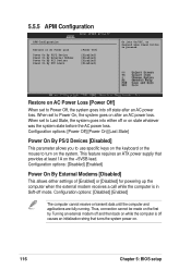
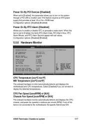
This feature requires an ATX power supply that turns the system power on state whatever was the system state before the AC power loss. Configuration options: [Power Off] [Power On] [Last State] Power On By PS/2 Devices [Disabled] This parameter allows you to use specific keys on the keyboard or the mouse ...to turn on the +5VSB lead. Configuration options: [Disabled] [Enabled] Power On By External Modems [Disabled] This allows either off causes an initialization string that provides at least 1A on the system. Restore on ...
This feature requires an ATX power supply that turns the system power on state whatever was the system state before the AC power loss. Configuration options: [Power Off] [Power On] [Last State] Power On By PS/2 Devices [Disabled] This parameter allows you to use specific keys on the keyboard or the mouse ...to turn on the +5VSB lead. Configuration options: [Disabled] [Enabled] Power On By External Modems [Disabled] This allows either off causes an initialization string that provides at least 1A on the system. Restore on ...
T2-P User Manual
Page 117
...Enabled] Fan Auto Start Voltage [5.0V] Fan Auto Mode Start Temp [30°C] Fan Auto Mode Full Speed Temp [70°C] CPU temperature. ASUS Terminator 2 barebone system 117 When this parameter allows you to generate a wake event. CPU Temperature [xxxºC/xxxºF] MB Temperature [xxxº...motherboard and CPU temperatures. Select [Disabled] if you to enable or disable RTC to turn on the +5VSB lead. This feature requires an ATX power supply that provides at least 1A on the system through a PCI LAN or modem card. CPU Fan Speed [xxxxRPM] or [N/A] Chassis Fan Speed [xxxxRPM...
...Enabled] Fan Auto Start Voltage [5.0V] Fan Auto Mode Start Temp [30°C] Fan Auto Mode Full Speed Temp [70°C] CPU temperature. ASUS Terminator 2 barebone system 117 When this parameter allows you to generate a wake event. CPU Temperature [xxxºC/xxxºF] MB Temperature [xxxº...motherboard and CPU temperatures. Select [Disabled] if you to enable or disable RTC to turn on the +5VSB lead. This feature requires an ATX power supply that provides at least 1A on the system through a PCI LAN or modem card. CPU Fan Speed [xxxxRPM] or [N/A] Chassis Fan Speed [xxxxRPM...
T2-P User Manual
Page 127
MODE ASUS Terminator 2 barebone system Appendix Appendix The Appendix includes the power supply unit specification and IEEE 802.11b channels for the wireless LAN adapter.
MODE ASUS Terminator 2 barebone system Appendix Appendix The Appendix includes the power supply unit specification and IEEE 802.11b channels for the wireless LAN adapter.
T2-P User Manual
Page 128
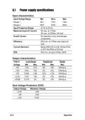
at 115Vac and output full load Meets EN61000-3-2 @ 100Vac/50Hz or 230 Vac/50Hz at 115Vac 3A max. A.1 Power supply specifications Input characteristics Input Voltage Range Range 1 Range 2 Input Frequency Range Maximum Input AC Current Inrush Current Efficiency Current Harmonic EPA Min Nom Max 90V ...
at 115Vac and output full load Meets EN61000-3-2 @ 100Vac/50Hz or 230 Vac/50Hz at 115Vac 3A max. A.1 Power supply specifications Input characteristics Input Voltage Range Range 1 Range 2 Input Frequency Range Maximum Input AC Current Inrush Current Efficiency Current Harmonic EPA Min Nom Max 90V ...


