Asus T2-PE1 Support and Manuals
Get Help and Manuals for this Asus item
Popular Asus T2-PE1 Manual Pages
T2-PE1 English User Manual E2151 - Page 19
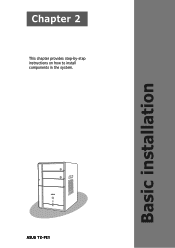
ASUS T2-PE1 Basic installation
Chapter 2
This chapter provides step-by-step instructions on how to install components in the system.
T2-PE1 English User Manual E2151 - Page 23
Carefully lift the fan and heatsink assembly, and set it aside.
2
2
2
2
1
ASUS T2-PE1
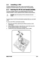
2-5 To remove the CPU fan and heatsink assembly:
1. Using a Phillips screwdriver, release the four screws that secure the fan and heatsink assembly to ensure optimum thermal condition and performance. D O N O T replace the proprietary CPU fan and heatsink with a surface mount LGA775 socket designed...
T2-PE1 English User Manual E2151 - Page 25
... you are installing a CPU.
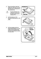
3. To prevent damage to a 135º angle. Lift the load plate with your thumb and forefinger to remove (B).
PnP cap Load plate
B A
ASUS T2-PE1
2-7
Retention tab A B Load lever
3
4. Press the load lever with your thumb (A), then move it to the left (B) until it is released from the load plate window to...
T2-PE1 English User Manual E2151 - Page 27
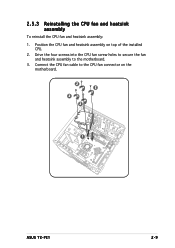
... and heatsink assembly
To reinstall the CPU fan and heatsink assembly: 1. Connect the CPU fan cable to the motherboard. 3. Position the CPU fan and heatsink assembly on the
motherboard.
2 2
2 2
1
ASUS T2-PE1
2-9 Drive the four screws into the CPU fan screw holes to secure the fan
and heatsink assembly to the CPU fan connector on top of the installed
CPU. 2.
T2-PE1 English User Manual E2151 - Page 29
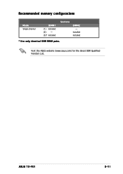
Visit the ASUS website (www.asus.com) for the latest DDR Qualified Vendors List. ASUS T2-PE1
2-11
Recommended memory configurations
Mode Single-channel
DIMM1 (1) Installed (2) - (3)* Installed
Sockets
DIMM2 -
Installed Installed
* Use only identical DDR DIMM pairs.
T2-PE1 English User Manual E2151 - Page 37
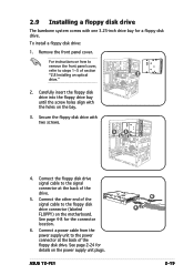
... 1~5 of the floppy disk drive. ASUS T2-PE1
6 4
2-19 Connect the other end of the signal cable to the signal connector at the back of section
"2.8 Installing an optical
2
drive."
2. See page 2-24 for details on the motherboard. Remove the front panel cover. See page 4-8 for a floppy disk drive.
For instructions on the bay.
3.
Connect...
T2-PE1 English User Manual E2151 - Page 41
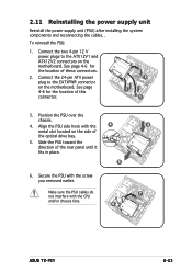
... power supply unit
Reinstall the power supply unit (PSU) after installing the system components and reconnecting the cables, . Connect the two... location of these connectors.
2. Position the PSU over the chassis.
4. Secure the PSU with the CPU and/or chassis fans.
4 5
6
3 7
ASUS T2-PE1
2-23 Connect the 24-pin ATX power plug to the ATX12V1 and ATX12V2 connectors on the motherboard....
T2-PE1 English User Manual E2151 - Page 55
... Preference panel
ASUS T2-PE1
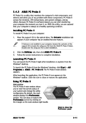
3-11 Launching PC Probe II
You can start installation.
2. Installing PC Probe II
To install PC Probe II on . Because PC Probe II is software-based, you can launch the PC Probe II right after installation or anytime from the Windows® desktop, click S t a r t > A l l P r o g r a m s > A S U S > P C P r o b e I I . 3. Follow the screen instructions to the...
T2-PE1 English User Manual E2151 - Page 57

...
Click to increase
value
Click to detach a monitor panel from the list box.
When you want to decrease
value
ASUS T2-PE1
3-13 You cannot adjust the sensor threshold values in two display modes: hexagonal (large) and rectangular (small).
You... the arrow down button of a system sensor such as fan rotation, CPU temperature, and voltages. You can now move together using the...
T2-PE1 English User Manual E2151 - Page 59
... of the window represents the used and available hard disk drive space.
Click
to display
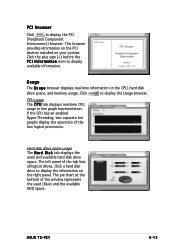
available information. CPU usage The C P U tab displays real-time CPU usage in line...tab displays the used (blue) and the available HDD space. ASUS T2-PE1
3-15 This browser
provides information on the PCI
devices installed on the CPU, hard disk
drive space, and memory usage. Click a ...
T2-PE1 English User Manual E2151 - Page 65
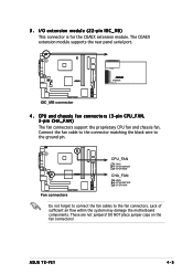
... the motherboard components. COM1
¤
¤
CGAEX
IOC_DC
IOC_MB connector
4 . CPU and chassis fan connectors (3-pin CPU_FAN, 3-pin CHA_FAN) The fan connectors support the proprietary CPU fan and chassis fan. DO NOT place jumper caps on the fan connectors!
ASUS T2-PE1
4-5 3 . The CGAEX extension module supports the rear panel serial port. I/O extension module (22-pin IOC_MB...
T2-PE1 English User Manual E2151 - Page 87
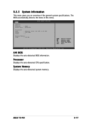
... system memory. Main
BIOS SETUP UTILITY
AMIBIOS Version : 0023 Build Date : 08/02/05
Processor Type Speed Count
: Genuine Intel (R) CPU 3.20 GHz : 3200 MHz : 1
System Memory
Size
: 192 MB
Select Screen
Select Item F1 General Help F10 Save and Exit ESC Exit
v02.58 (C)Copyright 1985-2004, American Megatrends, Inc. ASUS T2-PE1
5-17
T2-PE1 English User Manual E2151 - Page 89
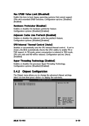
... to [Auto], the BIOS automatically checks the CPU's ability to enable TM or TM2 support.
In TM2 mode, CPU core ratio and VID will be reduced. In TM mode, power consumption is reduced. Configuration options: [Disabled] [Enabled]
CPU Internal Thermal Control [Auto]
Disables or automatically sets the CPU internal thermal control. ASUS T2-PE1
5-19 Configuration options: [Disabled] [Enabled...
T2-PE1 English User Manual E2151 - Page 95
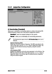
...CPU bus. Select one of this item. loads the standard settings for the system.
You can also type the desired memory frequency using the numeric keypad. ASUS T2-PE1...to set overclocking parameters. Memory Frequency [XXX] Allows you to [Manual]. Use the or keys to adjust the values. Use the or keys to adjust the values. 5.4.5 Jumperfree Configuration
Advanced
BIOS SETUP ...
T2-PE1 English User Manual E2151 - Page 99
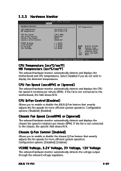
... and displays the CPU fan speed in rotations per minute (RPM). Configuration options: [Disabled] [Enabled]
Chassis Fan Speed [xxxxRPM] or [Ignored]
The onboard hardware monitor automatically detects and displays the chassis fan speed in rotations per minute (RPM). If the fan is not connected to display the detected temperatures.
ASUS T2-PE1
5-29
Chassis...
Asus T2-PE1 Reviews
We have not received any reviews for Asus yet.