T2-PE1 English User Manual E2151
Page 10
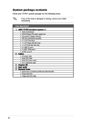
... e s y s t e m with • ASUS motherboard • 250 W Passive PFC power supply unit • PCI Express™ Gigabit LAN port • CPU fan and heatsink assembly • 2 x 5.25" drive bays • 1 x 3.5" floppy disk drive bay • 1 x 3.5" hard disk drive bay • 6 x USB 2.0 ports • 2 x IEEE 1394a ports • S/PDIF out port 2 . Item description 1 . User guide 5 . Support CD 4 . Cables • AC power cable • Serial ATA cable • Serial ATA power cable • 2-in-1 disk drive cable 3 . System package contents Check your T2-PE1 system package for the...
... e s y s t e m with • ASUS motherboard • 250 W Passive PFC power supply unit • PCI Express™ Gigabit LAN port • CPU fan and heatsink assembly • 2 x 5.25" drive bays • 1 x 3.5" floppy disk drive bay • 1 x 3.5" hard disk drive bay • 6 x USB 2.0 ports • 2 x IEEE 1394a ports • S/PDIF out port 2 . Item description 1 . User guide 5 . Support CD 4 . Cables • AC power cable • Serial ATA cable • Serial ATA power cable • 2-in-1 disk drive cable 3 . System package contents Check your T2-PE1 system package for the...
T2-PE1 English User Manual E2151
Page 12
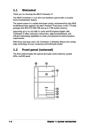
... to six (6) USB 2.0 ports and PCI Express Gigabit LAN, Terminator 2 offers extensive connectivity, digital entertainment, and efficient networking capabilities to 2 GB system memory. With these and many more, the Terminator 2 definitely delivers the cutting edge technology for choosing the ASUS Terminator 2! Supporting up to meet your computing and multimedia needs! 1.2 Front panel (external) The front panel includes the system and audio control buttons, system LEDs, and LED panel. 1 2 3 4 5 6 7 8 1-2 Chapter...
... to six (6) USB 2.0 ports and PCI Express Gigabit LAN, Terminator 2 offers extensive connectivity, digital entertainment, and efficient networking capabilities to 2 GB system memory. With these and many more, the Terminator 2 definitely delivers the cutting edge technology for choosing the ASUS Terminator 2! Supporting up to meet your computing and multimedia needs! 1.2 Front panel (external) The front panel includes the system and audio control buttons, system LEDs, and LED panel. 1 2 3 4 5 6 7 8 1-2 Chapter...
T2-PE1 English User Manual E2151
Page 15
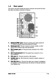
...specification. 3 . This port connects a mouse, modem, or other devices. 7 . This green 6-pin connector is for a PS/2 keyboard. 5 . This port connects a VGA monitor. 6 . This 25-pin port connects a printer, scanner, or other devices that allow convenient connection of this port becomes Front Speaker Out. This purple 6-pin connector is for 5.1-channel surround sound and enhanced 3D audio. 2 . P a r a l l e l p o r t . This Line Out (lime) port connects a headphone or a speaker. 1.4 Rear panel The system rear panel includes the power connector and several I F p o r t . ASUS T2...
...specification. 3 . This port connects a mouse, modem, or other devices. 7 . This green 6-pin connector is for a PS/2 keyboard. 5 . This port connects a VGA monitor. 6 . This 25-pin port connects a printer, scanner, or other devices that allow convenient connection of this port becomes Front Speaker Out. This purple 6-pin connector is for 5.1-channel surround sound and enhanced 3D audio. 2 . P a r a l l e l p o r t . This Line Out (lime) port connects a headphone or a speaker. 1.4 Rear panel The system rear panel includes the power connector and several I F p o r t . ASUS T2...
T2-PE1 English User Manual E2151
Page 16
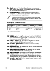
... is for details. 1-6 Chapter 1: System introduction E x p a n s i o n c a r d l o c k . See page 2-14 for the PSU fan that provides ventilation inside the power supply unit. 1 5 . This Line In (light blue) port connects a tape player or other audio sources. Refer to the table below for the power cable and plug. 1 6 . L A N ( R J - 4 5 ) p o r t . P o w e r c o n n e c t o r . V o l t a g e s e l e c t o r . Remove these cover when installing expansion cards. 1 3 . This connector is for connecting USB 2.0 devices such as a mouse, printer, scanner, camera, PDA, and others...
... is for details. 1-6 Chapter 1: System introduction E x p a n s i o n c a r d l o c k . See page 2-14 for the PSU fan that provides ventilation inside the power supply unit. 1 5 . This Line In (light blue) port connects a tape player or other audio sources. Refer to the table below for the power cable and plug. 1 6 . L A N ( R J - 4 5 ) p o r t . P o w e r c o n n e c t o r . V o l t a g e s e l e c t o r . Remove these cover when installing expansion cards. 1 3 . This connector is for connecting USB 2.0 devices such as a mouse, printer, scanner, camera, PDA, and others...
T2-PE1 English User Manual E2151
Page 20
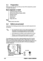
Hard disk drive 5. Expansion card(s) 4. Central processing unit (CPU) 2. Floppy disk drive Tool Phillips (cross) screw driver 2.2 Before you proceed Take note of the following precautions before you install components into the system. • Use a grounded wrist strap or touch a safely grounded object or a metal object, such as the power supply case, before installing any component, place it on a grounded antistatic pad or in the...
Hard disk drive 5. Expansion card(s) 4. Central processing unit (CPU) 2. Floppy disk drive Tool Phillips (cross) screw driver 2.2 Before you proceed Take note of the following precautions before you install components into the system. • Use a grounded wrist strap or touch a safely grounded object or a metal object, such as the power supply case, before installing any component, place it on a grounded antistatic pad or in the...
T2-PE1 English User Manual E2151
Page 22
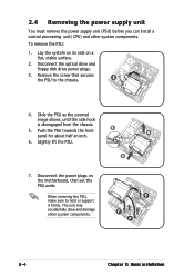
... must remove the power supply unit (PSU) before you can install a central processing unit( CPU) and other system components. 7 7 7 2-4 Chapter 2: Basic installation Slide the PSU as the zoomed image shows, until the side hook is disengaged from the chassis. 4 5. The unit may accidentally drop and damage other system components. Disconnect the optical drive and floppy disk drive power plugs. 3. When removing the PSU, make sure...
... must remove the power supply unit (PSU) before you can install a central processing unit( CPU) and other system components. 7 7 7 2-4 Chapter 2: Basic installation Slide the PSU as the zoomed image shows, until the side hook is disengaged from the chassis. 4 5. The unit may accidentally drop and damage other system components. Disconnect the optical drive and floppy disk drive power plugs. 3. When removing the PSU, make sure...
T2-PE1 English User Manual E2151
Page 33
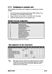
... unstable and the card inoperable. Assign an IRQ to the tables on shared slots, ensure that the drivers support "Share IRQ" or that the cards do not need IRQ assignments; ASUS T2-PE1 2-15 Onboard OHCI USB controller 2 -- -- -- shared -- -- -- -- See Chapter 5 for this motherboard A BCDE F GH PCI slot 1 -- IRQ assignments for information on the system and change the necessary BIOS settings, if any. shared Onboard Audio -- shared -- -- -- Turn on BIOS setup. 2.
... unstable and the card inoperable. Assign an IRQ to the tables on shared slots, ensure that the drivers support "Share IRQ" or that the cards do not need IRQ assignments; ASUS T2-PE1 2-15 Onboard OHCI USB controller 2 -- -- -- shared -- -- -- -- See Chapter 5 for this motherboard A BCDE F GH PCI slot 1 -- IRQ assignments for information on the system and change the necessary BIOS settings, if any. shared Onboard Audio -- shared -- -- -- Turn on BIOS setup. 2.
T2-PE1 English User Manual E2151
Page 34
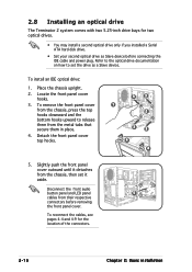
... connectors before connecting the IDE cable and power plug. To remove the front panel cover from the chassis, press the top hooks downward and the bottom hooks upward to set it detaches from the chassis, then set the drive as Slave device before removing the front panel cover. 2.8 Installing an optical drive The Terminator 2 system comes with two 5.25-inch drive bays for the location of the connectors. 2-16 Chapter 2: Basic installation...
... connectors before connecting the IDE cable and power plug. To remove the front panel cover from the chassis, press the top hooks downward and the bottom hooks upward to set it detaches from the chassis, then set the drive as Slave device before removing the front panel cover. 2.8 Installing an optical drive The Terminator 2 system comes with two 5.25-inch drive bays for the location of the connectors. 2-16 Chapter 2: Basic installation...
T2-PE1 English User Manual E2151
Page 38
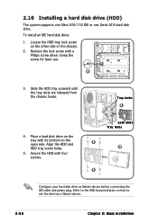
... 5 4 5 Configure your hard disk drive as a Master device. 2-20 Chapter 2: Basic installation Refer to the HDD documentation on how to set the drive as Master device before connecting the IDE cable and power plug. Slide the HDD tray outward until the tray slots are released from the chassis hooks. 2.10 Installing a hard disk drive (HDD) The system supports one Ultra ATA/133 IDE or one Serial ATA hard disk drive. Secure the HDD with a Philips screw driver. To install...
... 5 4 5 Configure your hard disk drive as a Master device. 2-20 Chapter 2: Basic installation Refer to the HDD documentation on how to set the drive as Master device before connecting the IDE cable and power plug. Slide the HDD tray outward until the tray slots are released from the chassis hooks. 2.10 Installing a hard disk drive (HDD) The system supports one Ultra ATA/133 IDE or one Serial ATA hard disk drive. Secure the HDD with a Philips screw driver. To install...
T2-PE1 English User Manual E2151
Page 40
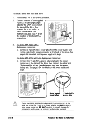
...a 4-pin (female) power plug from becoming unstable. D O N O T use either the 15-pin SATA power adapter plug O R the legacy 4-pin power connector. Connect the 15-pin SATA power adapter plug to a 4-pin (female) power plug from the power supply unit. To install a Serial ATA hard disk drive: 1. See page 2-24 for details on the motherboard. For Serial ATA HDDs with a 4-pin power connector: a. Chapter 2: Basic installation See page 4-8 for details on the power supply unit plugs. For Serial ATA HDDs without a 4-pin power connector: b. See page 2-25 for 2 the location of...
...a 4-pin (female) power plug from becoming unstable. D O N O T use either the 15-pin SATA power adapter plug O R the legacy 4-pin power connector. Connect the 15-pin SATA power adapter plug to a 4-pin (female) power plug from the power supply unit. To install a Serial ATA hard disk drive: 1. See page 2-24 for details on the motherboard. For Serial ATA HDDs with a 4-pin power connector: a. Chapter 2: Basic installation See page 4-8 for details on the power supply unit plugs. For Serial ATA HDDs without a 4-pin power connector: b. See page 2-25 for 2 the location of...
T2-PE1 English User Manual E2151
Page 42
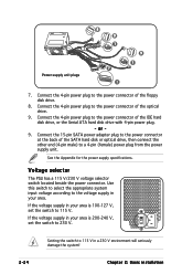
... V/230 V voltage selector switch located beside the power connector. Setting the switch to the power connector of the optical drive. 9. Connect the 4-pin power plug to 115 V in your area. Use this switch to select the appropriate system input voltage according to the power connector of the floppy disk drive. 8. Connect the 4-pin power plug to the voltage supply in a 230 V environment will seriously damage the system! 2-24 Chapter 2: Basic installation Connect the 15-pin SATA power adapter plug to 230 V. If...
... V/230 V voltage selector switch located beside the power connector. Setting the switch to the power connector of the optical drive. 9. Connect the 4-pin power plug to 115 V in your area. Use this switch to select the appropriate system input voltage according to the power connector of the floppy disk drive. 8. Connect the 4-pin power plug to the voltage supply in a 230 V environment will seriously damage the system! 2-24 Chapter 2: Basic installation Connect the 15-pin SATA power adapter plug to 230 V. If...
T2-PE1 English User Manual E2151
Page 46
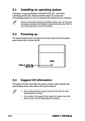
... the system contains useful software and several utility drivers that enhance the system features. • Screen display and driver options may not be the same for general reference only. Because motherboard settings and hardware options vary, use the setup procedures presented in this chapter for other operating system versions. • The contents of your OS documentation for updates. 3-2 Chapter 3: Starting up The system power button is located on the front...
... the system contains useful software and several utility drivers that enhance the system features. • Screen display and driver options may not be the same for general reference only. Because motherboard settings and hardware options vary, use the setup procedures presented in this chapter for other operating system versions. • The contents of your OS documentation for updates. 3-2 Chapter 3: Starting up The system power button is located on the front...
T2-PE1 English User Manual E2151
Page 47
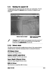
... audio driver. ASUS T2-PE1 3-3 ATI Chipset Driver Installs the ATI Chipset driver. E X E to activate the devices. Click an item to install Click an icon to display other information If A u t o r u n is enabled in your computer, browse the contents of the support CD to install the USB 2.0 driver. USB 2.0 Driver Click this item to locate the file ASSETUP.EXE from the BIN folder. Double-click the A S S E T U P . 3.3.1 Running the support CD To begin using...
... audio driver. ASUS T2-PE1 3-3 ATI Chipset Driver Installs the ATI Chipset driver. E X E to activate the devices. Click an item to install Click an icon to display other information If A u t o r u n is enabled in your computer, browse the contents of the support CD to install the USB 2.0 driver. USB 2.0 Driver Click this item to locate the file ASSETUP.EXE from the BIN folder. Double-click the A S S E T U P . 3.3.1 Running the support CD To begin using...
T2-PE1 English User Manual E2151
Page 48
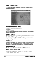
... an Internet connection either through a network or an Internet Service Provider (ISP). See page 5-8 for viewing files saved in Windows® environment. ASUS Ai Booster The ASUS Ai Booster application allows you to overclock the CPU speed in Portable Document Format (PDF). 3-4 Chapter 3: Starting up Agere Gigabit Ethernet Utility Installs the Agere Gigabit Ethernet utility. 3.3.3 Utilities menu The Utilities menu shows the applications and other software that allows you to update the motherboard BIOS and drivers.
... an Internet connection either through a network or an Internet Service Provider (ISP). See page 5-8 for viewing files saved in Windows® environment. ASUS Ai Booster The ASUS Ai Booster application allows you to overclock the CPU speed in Portable Document Format (PDF). 3-4 Chapter 3: Starting up Agere Gigabit Ethernet Utility Installs the Agere Gigabit Ethernet utility. 3.3.3 Utilities menu The Utilities menu shows the applications and other software that allows you to update the motherboard BIOS and drivers.
T2-PE1 English User Manual E2151
Page 51
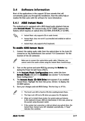
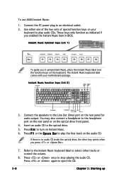
... conveniently guide you enabled Instant Music. Connect the analog audio cable from the optical drive to Instant Music mode, the system wake-up the system using the Instant Music function keys. 2. See section "5.4.6 Instant Music Configuration." 4. R O M D r i v e item appears if you through the installation. The onboard audio AC'97 CODEC supports this case, power up features (LAN, keyboard, mouse, USB) are deactivated. The I n s t a n t M u s i c and set to the 4-pin CD connector on the system and enter BIOS by...
... conveniently guide you enabled Instant Music. Connect the analog audio cable from the optical drive to Instant Music mode, the system wake-up the system using the Instant Music function keys. 2. See section "5.4.6 Instant Music Configuration." 4. R O M D r i v e item appears if you through the installation. The onboard audio AC'97 CODEC supports this case, power up features (LAN, keyboard, mouse, USB) are deactivated. The I n s t a n t M u s i c and set to the 4-pin CD connector on the system and enter BIOS by...
T2-PE1 English User Manual E2151
Page 52
... is no audio CD inside the optical drive, the drive tray ejects when you press or . 7. Instant Music function keys (Set 2) CD ON/OFF CAPS SCROLL LOCK LOCK LED LED PLAY/PAUSE STOP/EJECT PREVIOUS NEXT VOL. Press or again to an electrical outlet. 2. Press F 1 or the S p a c e B a r to the headphone port on the rear panel or on the audio CD. Connect the PC power plug to...
... is no audio CD inside the optical drive, the drive tray ejects when you press or . 7. Instant Music function keys (Set 2) CD ON/OFF CAPS SCROLL LOCK LOCK LED LED PLAY/PAUSE STOP/EJECT PREVIOUS NEXT VOL. Press or again to an electrical outlet. 2. Press F 1 or the S p a c e B a r to the headphone port on the rear panel or on the audio CD. Connect the PC power plug to...
T2-PE1 English User Manual E2151
Page 78
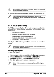
... install ASUS Update: 1. The ASUS Update utility is copied to manage, save, and update the motherboard BIOS in the optical drive. Doing so can cause system boot failure! 4. ASUS Update requires an Internet connection either through a network or an Internet Service Provider (ISP). See page 3-4 for this utility. 5-8 Chapter 5: BIOS setup Restart the system after the utility completes the updating process. Quit all Windows® applications before you to download the latest BIOS file. 5.1.5 ASUS Update utility The ASUS Update is available in the support...
... install ASUS Update: 1. The ASUS Update utility is copied to manage, save, and update the motherboard BIOS in the optical drive. Doing so can cause system boot failure! 4. ASUS Update requires an Internet connection either through a network or an Internet Service Provider (ISP). See page 3-4 for this utility. 5-8 Chapter 5: BIOS setup Restart the system after the utility completes the updating process. Quit all Windows® applications before you to download the latest BIOS file. 5.1.5 ASUS Update utility The ASUS Update is available in the support...
T2-PE1 English User Manual E2151
Page 81
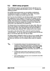
... test routines. Select the L o a d D e f a u l t S e t t i n g s item under the Exit Menu. 5.2 BIOS setup program This motherboard supports a programmable firmware chip that the computer can recognize these changes and record them in the CMOS RAM of your computer in the future. For example, you to use the Setup program, you wish to enter Setup after changing any BIOS settings, load the default settings to "Run Setup." otherwise, POST continues with the opportunity to enter the Setup utility...
... test routines. Select the L o a d D e f a u l t S e t t i n g s item under the Exit Menu. 5.2 BIOS setup program This motherboard supports a programmable firmware chip that the computer can recognize these changes and record them in the CMOS RAM of your computer in the future. For example, you to use the Setup program, you wish to enter Setup after changing any BIOS settings, load the default settings to "Run Setup." otherwise, POST continues with the opportunity to enter the Setup utility...
T2-PE1 English User Manual E2151
Page 85
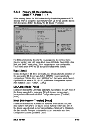
... Mode Block Mode PIO Mode Async DMA Ultra DMA SMART Monitoring BIOS SETUP UTILITY : Hard Disk : ST320410A : 20.0GB : Supported : 16 Sectors :4 : MultiWord DMA-2 : Ultra DMA-5 : Supported Select the type of device connected to Auto allows automatic selection of the appropriate IDE device type. Setting to the system. Select ARMD (ATAPI Removable Media Device) if your device is installed in the system. Select a device item then press to Auto enables the LBA mode if the device supports...
... Mode Block Mode PIO Mode Async DMA Ultra DMA SMART Monitoring BIOS SETUP UTILITY : Hard Disk : ST320410A : 20.0GB : Supported : 16 Sectors :4 : MultiWord DMA-2 : Ultra DMA-5 : Supported Select the type of device connected to Auto allows automatic selection of the appropriate IDE device type. Setting to the system. Select ARMD (ATAPI Removable Media Device) if your device is installed in the system. Select a device item then press to Auto enables the LBA mode if the device supports...
T2-PE1 English User Manual E2151
Page 105
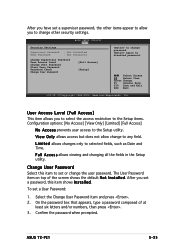
... Megatrends, Inc. User Access Level (Full Access] This item allows you to select the access restriction to the Setup items. Configuration options: [No Access] [View Only] [Limited] [Full Access] N o A c c e s s prevents user access to set or change the user password. Change User Password Select this item shows I n s t a l l e d. After you set a password, this item to the Setup utility. On the password box that appears, type a password composed of the screen shows the default N o t I n s t a l l e d. ASUS T2-PE1 5-35 To set a User Password: 1. Select the Change User Password item and...
... Megatrends, Inc. User Access Level (Full Access] This item allows you to select the access restriction to the Setup items. Configuration options: [No Access] [View Only] [Limited] [Full Access] N o A c c e s s prevents user access to set or change the user password. Change User Password Select this item shows I n s t a l l e d. After you set a password, this item to the Setup utility. On the password box that appears, type a password composed of the screen shows the default N o t I n s t a l l e d. ASUS T2-PE1 5-35 To set a User Password: 1. Select the Change User Password item and...


