T2-P User Manual
Page 4
... the volume 60 3.6 ASUS Wireless LAN adapter 61 3.6.1 LED indicators 62 3.6.2 Antenna installation 62 3.6.3 Installing the utilities and driver 63 3.6.4 Other support CD options 63 3.6.5 The Control Center utility 64 Chapter 4: Motherboard info 4.1 Introduction 76 4.2 Motherboard layout 76 4.3 Jumper 77 4.4 Connectors 78 Chapter 5: BIOS setup 5.1 Managing and updating your BIOS 88 5.1.1 Creating a bootable floppy disk 88 5.1.2 Using AFUDOS to copy the current BIOS 89 5.1.3 Using AFUDOS to update the BIOS 90 5.1.4 Using ASUS EZ Flash to update the BIOS 92 5.1.5 Recovering the...
... the volume 60 3.6 ASUS Wireless LAN adapter 61 3.6.1 LED indicators 62 3.6.2 Antenna installation 62 3.6.3 Installing the utilities and driver 63 3.6.4 Other support CD options 63 3.6.5 The Control Center utility 64 Chapter 4: Motherboard info 4.1 Introduction 76 4.2 Motherboard layout 76 4.3 Jumper 77 4.4 Connectors 78 Chapter 5: BIOS setup 5.1 Managing and updating your BIOS 88 5.1.1 Creating a bootable floppy disk 88 5.1.2 Using AFUDOS to copy the current BIOS 89 5.1.3 Using AFUDOS to update the BIOS 90 5.1.4 Using ASUS EZ Flash to update the BIOS 92 5.1.5 Recovering the...
T2-P User Manual
Page 8
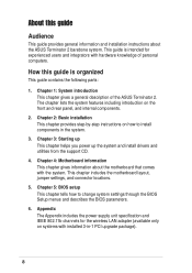
... following parts: 1. Chapter 2: Basic installation This chapter provides step-by-step instructions on the front and rear panel, and internal components. 2. This chapter includes the motherboard layout, jumper settings, and connector locations. 5. Safeguards About this guide is intended for the wireless LAN adapter (available only on systems with hardware knowledge of the ASUS Terminator 2. Appendix The Appendix includes the power supply unit specification and IEEE 802.11b channels for experienced users and...
... following parts: 1. Chapter 2: Basic installation This chapter provides step-by-step instructions on the front and rear panel, and internal components. 2. This chapter includes the motherboard layout, jumper settings, and connector locations. 5. Safeguards About this guide is intended for the wireless LAN adapter (available only on systems with hardware knowledge of the ASUS Terminator 2. Appendix The Appendix includes the power supply unit specification and IEEE 802.11b channels for experienced users and...
T2-P User Manual
Page 10
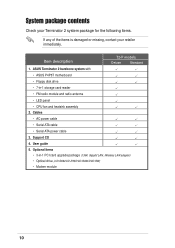
...; LED panel • CPU fan and heatsink assembly 2. Support CD 4. Item description T2-P models Deluxe Standard 1. System package contents Check your Terminator 2 system package for the following items. If any of the items is damaged or missing, contact your retailer immediately. ASUS Terminator 2 barebone system with • ASUS P4P8T motherboard • Floppy disk drive • 7-in -1 PCI card upgrade package (1394, Gigabit LAN, Wireless LAN adapter) • Optical drive (CD-ROM/CD...
...; LED panel • CPU fan and heatsink assembly 2. Support CD 4. Item description T2-P models Deluxe Standard 1. System package contents Check your Terminator 2 system package for the following items. If any of the items is damaged or missing, contact your retailer immediately. ASUS Terminator 2 barebone system with • ASUS P4P8T motherboard • Floppy disk drive • 7-in -1 PCI card upgrade package (1394, Gigabit LAN, Wireless LAN adapter) • Optical drive (CD-ROM/CD...
T2-P User Manual
Page 13
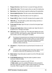
This door covers a second optical drive bay. 5. Power LED . HDD LED . Storage card reader door (Deluxe models only). LED panel (Deluxe models only). The following front panel buttons are available on the OS setting. 12. Floppy drive door. This door opens when you to preset a radio station. Power button . When lit, this door to access the 6-in Audio DJ mode. The audio control buttons are activated only when the system is in -1 storage card reader. 10. Mode button. In Radio mode, scans...
This door covers a second optical drive bay. 5. Power LED . HDD LED . Storage card reader door (Deluxe models only). LED panel (Deluxe models only). The following front panel buttons are available on the OS setting. 12. Floppy drive door. This door opens when you to preset a radio station. Power button . When lit, this door to access the 6-in Audio DJ mode. The audio control buttons are activated only when the system is in -1 storage card reader. 10. Mode button. In Radio mode, scans...
T2-P User Manual
Page 18
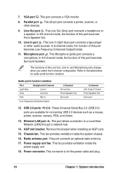
... Surround Speaker. Radio antenna port. This connector is for connecting USB 2.0 devices such as a mouse, printer, scanner, camera, PDA, and others. 13. This Line In (light blue) port connects a tape player or other devices. 9. This port allows connection to the table below for audio ports function variation. Parallel port . These Universal Serial Bus 2.0 (USB 2.0) ports are available for the power cable and plug. 18 Chapter 1: System introduction Power supply unit fan. This Microphone (pink) port connects a microphone. Audio ports...
... Surround Speaker. Radio antenna port. This connector is for connecting USB 2.0 devices such as a mouse, printer, scanner, camera, PDA, and others. 13. This Line In (light blue) port connects a tape player or other devices. 9. This port allows connection to the table below for audio ports function variation. Parallel port . These Universal Serial Bus 2.0 (USB 2.0) ports are available for the power cable and plug. 18 Chapter 1: System introduction Power supply unit fan. This Microphone (pink) port connects a microphone. Audio ports...
T2-P User Manual
Page 34
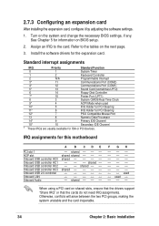
... the two PCI groups, making the system unstable and the card inoperable. 34 Chapter 2: Basic installation 2.7.3 Configuring an expansion card After installing the expansion card, configure it by adjusting the software settings. 1. When using a PCI card on the system and change the necessary BIOS settings, if any. Turn on shared slots, ensure that the drivers support "Share IRQ" or that the cards do not need IRQ assignments. shared -- -- -- -- -- -- -- See Chapter 5 for ISA or PCI devices.
... the two PCI groups, making the system unstable and the card inoperable. 34 Chapter 2: Basic installation 2.7.3 Configuring an expansion card After installing the expansion card, configure it by adjusting the software settings. 1. When using a PCI card on the system and change the necessary BIOS settings, if any. Turn on shared slots, ensure that the drivers support "Share IRQ" or that the cards do not need IRQ assignments. shared -- -- -- -- -- -- -- See Chapter 5 for ISA or PCI devices.
T2-P User Manual
Page 37
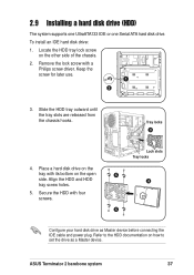
... later use. 1 2 3. Slide the HDD tray outward until the tray slots are released from the chassis hooks. Secure the HDD with a Philips screw driver. ASUS Terminator 2 barebone system 37 Refer to set the drive as Master device before connecting the IDE cable and power plug. 2.9 Installing a hard disk drive (HDD) The system supports one UltraATA133 IDE or one Serial ATA hard disk drive. Tray locks 3 4. Lock slots Tray locks 5 4 5 Configure your hard disk drive as a Master device. Locate the HDD tray...
... later use. 1 2 3. Slide the HDD tray outward until the tray slots are released from the chassis hooks. Secure the HDD with a Philips screw driver. ASUS Terminator 2 barebone system 37 Refer to set the drive as Master device before connecting the IDE cable and power plug. 2.9 Installing a hard disk drive (HDD) The system supports one UltraATA133 IDE or one Serial ATA hard disk drive. Tray locks 3 4. Lock slots Tray locks 5 4 5 Configure your hard disk drive as a Master device. Locate the HDD tray...
T2-P User Manual
Page 38
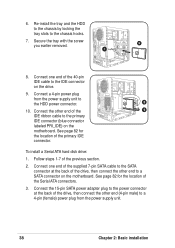
... Serial ATA connectors. 3. Connect a 4-pin power plug from the power supply unit. 38 Chapter 2: Basic installation See page 82 for the location of the primary IDE connector. To install a Serial ATA hard disk drive: 1. Connect the other end (4-pin male) to the primary IDE connector (blue connector labeled PRI_IDE) on the motherboard. Follow steps 1-7 of the 9 IDE ribbon cable to a 4-pin (female) power plug from the power supply unit to the chassis hooks. 7. Connect the 15-pin SATA power adapter plug to the power connector...
... Serial ATA connectors. 3. Connect a 4-pin power plug from the power supply unit. 38 Chapter 2: Basic installation See page 82 for the location of the primary IDE connector. To install a Serial ATA hard disk drive: 1. Connect the other end (4-pin male) to the primary IDE connector (blue connector labeled PRI_IDE) on the motherboard. Follow steps 1-7 of the 9 IDE ribbon cable to a 4-pin (female) power plug from the power supply unit to the chassis hooks. 7. Connect the 15-pin SATA power adapter plug to the power connector...
T2-P User Manual
Page 46
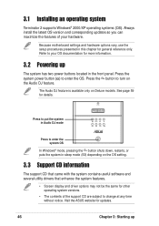
... updates. 46 Chapter 3: Starting up The system has two power buttons located in sleep mode (S3) depending on the OS setting. 3.3 Support CD information The support CD that came with the system contains useful software and several utility drivers that enhance the system features. • Screen display and driver options may not be the same for general reference only. Visit the ASUS website for details. Because motherboard settings and hardware options vary, use the setup...
... updates. 46 Chapter 3: Starting up The system has two power buttons located in sleep mode (S3) depending on the OS setting. 3.3 Support CD information The support CD that came with the system contains useful software and several utility drivers that enhance the system features. • Screen display and driver options may not be the same for general reference only. Visit the ASUS website for details. Because motherboard settings and hardware options vary, use the setup...
T2-P User Manual
Page 47
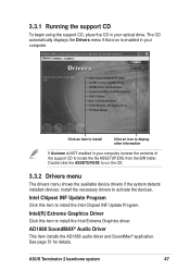
... your optical drive. Intel(R) Extreme Graphics Driver Click this item to activate the devices. ASUS Terminator 2 barebone system 47 The CD automatically displays the Drivers menu if Autorun is NOT enabled in your computer, browse the contents of the support CD to install the Intel Extreme Graphics driver. Install the necessary drivers to install the Intel Chipset INF Update Program. Intel Chipset INF Update Program Click this item to locate...
... your optical drive. Intel(R) Extreme Graphics Driver Click this item to activate the devices. ASUS Terminator 2 barebone system 47 The CD automatically displays the Drivers menu if Autorun is NOT enabled in your computer, browse the contents of the support CD to install the Intel Extreme Graphics driver. Install the necessary drivers to install the Intel Chipset INF Update Program. Intel Chipset INF Update Program Click this item to locate...
T2-P User Manual
Page 48
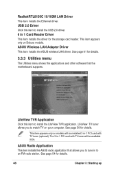
... in 1 Card Reader Driver This item installs the driver for details. 3.3.3 Utilities menu The Utilities menu shows the applications and other software that allows you to an FM radio station. The 3-in -1 PCI card with TV tuner will be available soon. This item appears only on models with an installed 3-in -1 PCI card with TV tuner (optional). RealtekRTL8100C 10/100M LAN Driver This item installs the Ethernet driver. ASUS Wireless LAN Adapter Driver This item installs the ASUS wireless LAN driver. This...
... in 1 Card Reader Driver This item installs the driver for details. 3.3.3 Utilities menu The Utilities menu shows the applications and other software that allows you to an FM radio station. The 3-in -1 PCI card with TV tuner will be available soon. This item appears only on models with an installed 3-in -1 PCI card with TV tuner (optional). RealtekRTL8100C 10/100M LAN Driver This item installs the Ethernet driver. ASUS Wireless LAN Adapter Driver This item installs the ASUS wireless LAN driver. This...
T2-P User Manual
Page 49
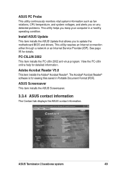
... problems. This utility helps you to update the motherboard BIOS and drivers. ASUS Terminator 2 barebone system 49 PC-CILLIN 2002 This item installs the PC-cillin 2002 anti-virus program. The Acrobat® Acrobat Reader® software is for viewing files saved in a healthy operating condition. View the PC-cillin online help for details. This utility requires an Internet connection either through a network or an Internet Service...
... problems. This utility helps you to update the motherboard BIOS and drivers. ASUS Terminator 2 barebone system 49 PC-CILLIN 2002 This item installs the PC-cillin 2002 anti-virus program. The Acrobat® Acrobat Reader® software is for viewing files saved in a healthy operating condition. View the PC-cillin online help for details. This utility requires an Internet connection either through a network or an Internet Service...
T2-P User Manual
Page 51
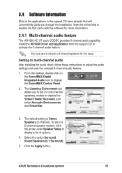
... display a list of the applications in the support CD have wizards that came with the software for this setup. The Listening Environment tab allows you through the installation. Click the Apply button. Install the AD1888 Driver and Application from the support CD to multi-channel speakers, enable or disable the Virtual Theater Surround, and select Acoustic Environments and Virtual Ear. 3. Select the option Surround Sound Speakers...
... display a list of the applications in the support CD have wizards that came with the software for this setup. The Listening Environment tab allows you through the installation. Click the Apply button. Install the AD1888 Driver and Application from the support CD to multi-channel speakers, enable or disable the Virtual Theater Surround, and select Acoustic Environments and Virtual Ear. 3. Select the option Surround Sound Speakers...
T2-P User Manual
Page 56
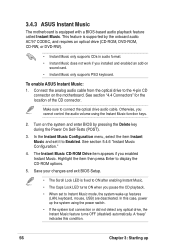
... you installed and enabled an add-on the motherboard. In the Instant Music Configuration menu, select the item Instant Music and set to the 4-pin CD connector on sound card. • Instant Music only supports PS/2 keyboard. In this condition. 56 Chapter 3: Starting up the system using the Instant Music function keys. 2. See section "4.4 Connectors" for the location of the CD connector. Highlight the item then press Enter to connect the optical drive audio cable. Connect...
... you installed and enabled an add-on the motherboard. In the Instant Music Configuration menu, select the item Instant Music and set to the 4-pin CD connector on sound card. • Instant Music only supports PS/2 keyboard. In this condition. 56 Chapter 3: Starting up the system using the Instant Music function keys. 2. See section "4.4 Connectors" for the location of the CD connector. Highlight the item then press Enter to connect the optical drive audio cable. Connect...
T2-P User Manual
Page 57
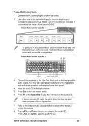
... PC power plug to the optical drive. 5. Press F1 or the Space Bar to the Line Out (lime) port on the audio CD. Refer to the Instant Music keyboard label to stop playing the audio CD. DOWN VOL. Connect the speakers to play audio CDs. You may also connect a headphone to turn on the optical drive front panel. 4. Press or once to select other tracks or control...
... PC power plug to the optical drive. 5. Press F1 or the Space Bar to the Line Out (lime) port on the audio CD. Refer to the Instant Music keyboard label to stop playing the audio CD. DOWN VOL. Connect the speakers to play audio CDs. You may also connect a headphone to turn on the optical drive front panel. 4. Press or once to select other tracks or control...
T2-P User Manual
Page 65
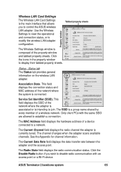
... hardware address of the network where the system is connected. See the Appendix for channel information. Click the Disable Radio button if you to a network. Association State. Click the icons in the property window to modify the wireless LAN adapter configuration. Status tab The Status tab provides general information on the wireless LAN adapter. This field displays the connection status and MAC address of a device connected to control the ASUS wireless LAN adapter...
... hardware address of the network where the system is connected. See the Appendix for channel information. Click the Disable Radio button if you to a network. Association State. Click the icons in the property window to modify the wireless LAN adapter configuration. Status tab The Status tab provides general information on the wireless LAN adapter. This field displays the connection status and MAC address of a device connected to control the ASUS wireless LAN adapter...
T2-P User Manual
Page 73
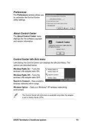
...The Control Center left -click Menu. Wireless Radio On - Search & Connect - View available wireless networks within range. About Control Center The About Control Center menu displays the the software copyright and version information. Control Center left-click menu Left-clicking the Control Center icon displays the left -click menu is available only when the adapter is set to customize the Control Center Utility settings. Wireless Option - Sets your Windows® XP wireless networking environment. Turns the wireless LAN adapter radio ON. Turns the wireless LAN adapter radio OFF. ASUS...
...The Control Center left -click Menu. Wireless Radio On - Search & Connect - View available wireless networks within range. About Control Center The About Control Center menu displays the the software copyright and version information. Control Center left-click menu Left-clicking the Control Center icon displays the left -click menu is available only when the adapter is set to customize the Control Center Utility settings. Wireless Option - Sets your Windows® XP wireless networking environment. Turns the wireless LAN adapter radio ON. Turns the wireless LAN adapter radio OFF. ASUS...
T2-P User Manual
Page 95
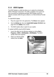
... The Drivers menu appears. 2. See page 49 for the Utilities menu screen. 3. To update the BIOS using the ASUS Update: 1. Click the Utilities tab, then click Install ASUS Update VX.XX.XX. Select your system. ASUS Update requires an Internet connection either through a network or an Internet Service Provider (ISP). The ASUS Update initial screen appears. 2. The ASUS Update utility is a utility that comes with the motherboard package. Launch the utility from the Windows desktop by clicking Start > Programs > ASUS > ASUSUpdate > ASUSUpdate. 5.1.6 ASUS Update The ASUS Update is...
... The Drivers menu appears. 2. See page 49 for the Utilities menu screen. 3. To update the BIOS using the ASUS Update: 1. Click the Utilities tab, then click Install ASUS Update VX.XX.XX. Select your system. ASUS Update requires an Internet connection either through a network or an Internet Service Provider (ISP). The ASUS Update initial screen appears. 2. The ASUS Update utility is a utility that comes with the motherboard package. Launch the utility from the Windows desktop by clicking Start > Programs > ASUS > ASUSUpdate > ASUSUpdate. 5.1.6 ASUS Update The ASUS Update is...
T2-P User Manual
Page 101
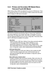
... BIOS and are specifically configuring a CD-ROM drive. Setting to the device occurs one sector at a time if the device supports multi-sector transfer feature. Select CDROM if you are not user-configurable. Configuration options: [Disabled] [Auto] ASUS Terminator 2 barebone system 101 These items show N/A if no IDE device is either a ZIP, LS-120, or MO drive. Select ARMD (ATAPI Removable Media Device) if your device is installed in the system. Configuration options: [Not Installed...
... BIOS and are specifically configuring a CD-ROM drive. Setting to the device occurs one sector at a time if the device supports multi-sector transfer feature. Select CDROM if you are not user-configurable. Configuration options: [Disabled] [Auto] ASUS Terminator 2 barebone system 101 These items show N/A if no IDE device is either a ZIP, LS-120, or MO drive. Select ARMD (ATAPI Removable Media Device) if your device is installed in the system. Configuration options: [Not Installed...
T2-P User Manual
Page 112
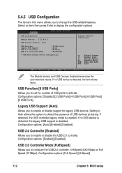
...] [Enabled] [Disabled] USB 2.0 Controller [Enabled] Allows you to enable or disable support for legacy USB devices. Configuration options: [Enabled] [Disabled] USB 2.0 Controller Mode [FullSpeed] Allows you to set the number of USB devices at startup. Configuration options: [Disabled] [2 USB Ports] [4 USB Ports] [6 USB Ports] [8 USB Ports] Legacy USB Support [Auto] Allows you to activate. If no USB device is disabled. Select an item then press Enter to change the USB-related features. Configuration options: [Full Speed ] [Hi Speed] 112 Chapter 5: BIOS setup Setting...
...] [Enabled] [Disabled] USB 2.0 Controller [Enabled] Allows you to enable or disable support for legacy USB devices. Configuration options: [Enabled] [Disabled] USB 2.0 Controller Mode [FullSpeed] Allows you to set the number of USB devices at startup. Configuration options: [Disabled] [2 USB Ports] [4 USB Ports] [6 USB Ports] [8 USB Ports] Legacy USB Support [Auto] Allows you to activate. If no USB device is disabled. Select an item then press Enter to change the USB-related features. Configuration options: [Full Speed ] [Hi Speed] 112 Chapter 5: BIOS setup Setting...


