T2-P User Manual
Page 4
... radio station 59 3.5.3 Presetting a station 60 3.5.4 Adjusting the volume 60 3.6 ASUS Wireless LAN adapter 61 3.6.1 LED indicators 62 3.6.2 Antenna installation 62 3.6.3 Installing the utilities and driver 63 3.6.4 Other support CD options 63 3.6.5 The Control Center utility 64 Chapter 4: Motherboard info 4.1 Introduction 76 4.2 Motherboard layout 76 4.3 Jumper 77 4.4 Connectors 78 Chapter 5: BIOS setup 5.1 Managing...
... radio station 59 3.5.3 Presetting a station 60 3.5.4 Adjusting the volume 60 3.6 ASUS Wireless LAN adapter 61 3.6.1 LED indicators 62 3.6.2 Antenna installation 62 3.6.3 Installing the utilities and driver 63 3.6.4 Other support CD options 63 3.6.5 The Control Center utility 64 Chapter 4: Motherboard info 4.1 Introduction 76 4.2 Motherboard layout 76 4.3 Jumper 77 4.4 Connectors 78 Chapter 5: BIOS setup 5.1 Managing...
T2-P User Manual
Page 8
...This chapter helps you power up the system and install drivers and utilities from the support CD. 4. Chapter 4: Motherboard information This chapter gives information about the ASUS Terminator 2 barebone system. Safeguards About this guide is intended for the wireless LAN adapter (available only on the ... the BIOS parameters. 6. This guide is organized This guide contains the following parts: 1. This chapter includes the motherboard layout, jumper settings, and connector locations. 5. Chapter 5: BIOS setup This chapter tells how to install components in -1 PCI upgrade package). ...
...This chapter helps you power up the system and install drivers and utilities from the support CD. 4. Chapter 4: Motherboard information This chapter gives information about the ASUS Terminator 2 barebone system. Safeguards About this guide is intended for the wireless LAN adapter (available only on the ... the BIOS parameters. 6. This guide is organized This guide contains the following parts: 1. This chapter includes the motherboard layout, jumper settings, and connector locations. 5. Chapter 5: BIOS setup This chapter tells how to install components in -1 PCI upgrade package). ...
T2-P User Manual
Page 10
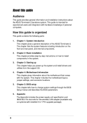
...• FM radio module and radio antenna • LED panel • CPU fan and heatsink assembly 2. ASUS Terminator 2 barebone system with • ASUS P4P8T motherboard • Floppy disk drive • 7-in -1 PCI card upgrade package (1394, Gigabit LAN, Wireless LAN... adapter) • Optical drive (CD-ROM/CD-RW/DVD-ROM/DVD-RW) • Modem module 10 Cables • AC power cable • Serial ATA cable • Serial ATA power cable 3. Item description T2...
...• FM radio module and radio antenna • LED panel • CPU fan and heatsink assembly 2. ASUS Terminator 2 barebone system with • ASUS P4P8T motherboard • Floppy disk drive • 7-in -1 PCI card upgrade package (1394, Gigabit LAN, Wireless LAN... adapter) • Optical drive (CD-ROM/CD-RW/DVD-ROM/DVD-RW) • Modem module 10 Cables • AC power cable • Serial ATA cable • Serial ATA power cable 3. Item description T2...
T2-P User Manual
Page 12
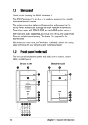
... and audio capabilities, extensive connectivity, and Gigabit/Fast Ethernet and wireless networking, Terminator 2 is an all-in a stylish mini-tower casing, and powered by the ASUS P4P8T motherboard that supports Intel® Pentium® 4 Northwood/ Prescott processor with a versatile home entertainment feature. With these and many more, the Terminator 2 definitely delivers the...
... and audio capabilities, extensive connectivity, and Gigabit/Fast Ethernet and wireless networking, Terminator 2 is an all-in a stylish mini-tower casing, and powered by the ASUS P4P8T motherboard that supports Intel® Pentium® 4 Northwood/ Prescott processor with a versatile home entertainment feature. With these and many more, the Terminator 2 definitely delivers the...
T2-P User Manual
Page 20
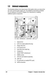
ASUS P4P8T motherboard 8. 1.5 Internal components The illustration below is the internal view of the system when you remove the top cover and the power supply unit. Floppy disk ...
ASUS P4P8T motherboard 8. 1.5 Internal components The illustration below is the internal view of the system when you remove the top cover and the power supply unit. Floppy disk ...
T2-P User Manual
Page 24
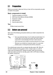
..., and not powered OFF. Central processing unit (CPU) 2. Hard disk drive 5. When lit, this LED indicates that came with an onboard standby power LED. The motherboard comes with the component. DDR Dual Inline Memory Module (DIMM) 3. Second optical drive Tool Phillips (cross) screw driver 2.2 Before you proceed Take note of the...
..., and not powered OFF. Central processing unit (CPU) 2. Hard disk drive 5. When lit, this LED indicates that came with an onboard standby power LED. The motherboard comes with the component. DDR Dual Inline Memory Module (DIMM) 3. Second optical drive Tool Phillips (cross) screw driver 2.2 Before you proceed Take note of the...
T2-P User Manual
Page 26
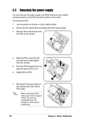
Lay the system on its side on the motherboard, then set the PSU aside. Slide the PSU to hold or support it firmly. Disconnect the power plugs on a flat, stable surface. 2. Push the PSU ...
Lay the system on its side on the motherboard, then set the PSU aside. Slide the PSU to hold or support it firmly. Disconnect the power plugs on a flat, stable surface. 2. Push the PSU ...

T2-P User Manual
Page 27
... and heatsink assembly The system package includes a pre-installed proprietary CPU fan and heatsink assembly to remove the second retention bracket. 4 ASUS Terminator 2 barebone system 3 27 Do steps 1 to 4 to ensure optimum thermal condition and performance. Detach the retention bracket hook from... the hole on the other models. 2.5 Installing a CPU The P4P8T motherboard comes with other side of the retention module, then lift. 5. To remove the CPU fan and heatsink assembly: 1. You must remove...
... and heatsink assembly The system package includes a pre-installed proprietary CPU fan and heatsink assembly to remove the second retention bracket. 4 ASUS Terminator 2 barebone system 3 27 Do steps 1 to 4 to ensure optimum thermal condition and performance. Detach the retention bracket hook from... the hole on the other models. 2.5 Installing a CPU The P4P8T motherboard comes with other side of the retention module, then lift. 5. To remove the CPU fan and heatsink assembly: 1. You must remove...
T2-P User Manual
Page 28
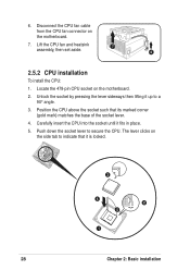
Disconnect the CPU fan cable from the CPU fan connector on the motherboard. 2. The lever clicks on the side tab to a 90° angle. 3. Unlock the socket by pressing the lever sideways then lifting it up to indicate ... the CPU: 1. Carefully insert the CPU into the socket until it is locked. 3 4 2 5 1 28 Chapter 2: Basic installation Locate the 478-pin CPU socket on the motherboard. 7.
Disconnect the CPU fan cable from the CPU fan connector on the motherboard. 2. The lever clicks on the side tab to a 90° angle. 3. Unlock the socket by pressing the lever sideways then lifting it up to indicate ... the CPU: 1. Carefully insert the CPU into the socket until it is locked. 3 4 2 5 1 28 Chapter 2: Basic installation Locate the 478-pin CPU socket on the motherboard. 7.
T2-P User Manual
Page 29
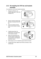
Carefully press down the locking lever on the motherboard. Connect the CPU fan cable to re-install the second retention bracket. 7. Follow steps 2 to 5 to the CPU fan connector on the other side of ... CPU. 1 2. Position the CPU fan and heatsink assembly on the side of the CPU fan. 3. Attach the locking lever hook into the retention module 3 2 hole. 4. ASUS Terminator 2 barebone system 29 Attach the retention bracket hook into the retention module hole to secure the fan and heatsink assembly in place. 4 7 5 6. 2.5.3 Re-installing...
Carefully press down the locking lever on the motherboard. Connect the CPU fan cable to re-install the second retention bracket. 7. Follow steps 2 to 5 to the CPU fan connector on the other side of ... CPU. 1 2. Position the CPU fan and heatsink assembly on the side of the CPU fan. 3. Attach the locking lever hook into the retention module 3 2 hole. 4. ASUS Terminator 2 barebone system 29 Attach the retention bracket hook into the retention module hole to secure the fan and heatsink assembly in place. 4 7 5 6. 2.5.3 Re-installing...
T2-P User Manual
Page 30
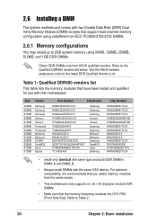
... only identical (the same type and size) DDR DIMM in DIMM_A and DIMM_B. • Always install DIMMs with this motherboard. For optimum compatibility, it is recommended that you obtain memory modules from ASUS qualified vendors. Refer to the Qualified DDR400 vendors list below. Refer to Table 2. 30 Chapter 2: Basic installation Table 1: Qualified...
... only identical (the same type and size) DDR DIMM in DIMM_A and DIMM_B. • Always install DIMMs with this motherboard. For optimum compatibility, it is recommended that you obtain memory modules from ASUS qualified vendors. Refer to the Qualified DDR400 vendors list below. Refer to Table 2. 30 Chapter 2: Basic installation Table 1: Qualified...
T2-P User Manual
Page 31
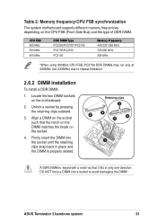
... DIMM into a socket to chipset limitation. 2.6.2 DIMM installation To install a DDR DIMM. 1. Locate the two DIMM sockets on the socket. 4. ASUS Terminator 2 barebone system 31 Align a DIMM on the socket such that it fits in only one direction. DO NOT force a DIMM into the ...keyed with a notch so that the notch on the DIMM matches the break on the motherboard. 2. Unlock a socket by pressing the retaining clips outward. 3. Table 2: Memory frequency/CPU FSB synchronization The system motherboard supports different memory frequencies depending on the CPU FSB (Front Side Bus) and the ...
... DIMM into a socket to chipset limitation. 2.6.2 DIMM installation To install a DDR DIMM. 1. Locate the two DIMM sockets on the socket. 4. ASUS Terminator 2 barebone system 31 Align a DIMM on the socket such that it fits in only one direction. DO NOT force a DIMM into the ...keyed with a notch so that the notch on the DIMM matches the break on the motherboard. 2. Unlock a socket by pressing the retaining clips outward. 3. Table 2: Memory frequency/CPU FSB synchronization The system motherboard supports different memory frequencies depending on the CPU FSB (Front Side Bus) and the ...
T2-P User Manual
Page 32
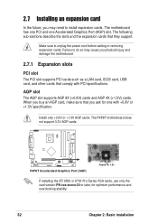
...30 or later, for one Accelerated Graphics Port (AGP) slot. Make sure to install expansion cards. Install only +0.8V or +1.5V AGP cards. The P4P8T motherboard does not support 3.3V AGP cards. AGP slot The AGP slot supports AGP 8X (+0.8V) cards and AGP 4X (+1.5V) cards. When you buy an... AGP card, make sure that you physical injury and damage the motherboard. 2.7.1 Expansion slots PCI slot The PCI slot supports PCI cards such as a LAN card, SCSI card, USB card, and other cards that they support. 2.7 ...
...30 or later, for one Accelerated Graphics Port (AGP) slot. Make sure to install expansion cards. Install only +0.8V or +1.5V AGP cards. The P4P8T motherboard does not support 3.3V AGP cards. AGP slot The AGP slot supports AGP 8X (+0.8V) cards and AGP 4X (+1.5V) cards. When you buy an... AGP card, make sure that you physical injury and damage the motherboard. 2.7.1 Expansion slots PCI slot The PCI slot supports PCI cards such as a LAN card, SCSI card, USB card, and other cards that they support. 2.7 ...
T2-P User Manual
Page 34
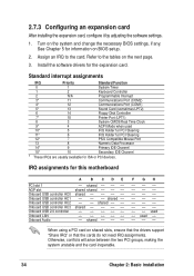
See Chapter 5 for ISA or PCI devices. Refer to the card. shared -- -- -- shared -- -- Install the software drivers for this motherboard PCI slot 1 AGP slot Onboard USB controller HC0 Onboard USB controller HC1 Onboard USB controller HC2 Onboard USB controller HC3 Onboard USB 2.0 controller Onboard LAN ...
See Chapter 5 for ISA or PCI devices. Refer to the card. shared -- -- -- shared -- -- Install the software drivers for this motherboard PCI slot 1 AGP slot Onboard USB controller HC0 Onboard USB controller HC1 Onboard USB controller HC2 Onboard USB controller HC3 Onboard USB 2.0 controller Onboard LAN ...
T2-P User Manual
Page 36
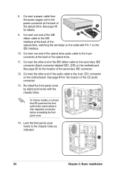
Connect the other end of the IDE ribbon cable to the 4-pin CD1 connector on the motherboard. Connect the other end of the audio cable to the secondary IDE connector (black connector labeled SEC_IDE) on the motherboard. Lock the front panel cover hooks to the 4-pin connector at the back of the secondary...
Connect the other end of the IDE ribbon cable to the 4-pin CD1 connector on the motherboard. Connect the other end of the audio cable to the secondary IDE connector (black connector labeled SEC_IDE) on the motherboard. Lock the front panel cover hooks to the 4-pin connector at the back of the secondary...
T2-P User Manual
Page 38
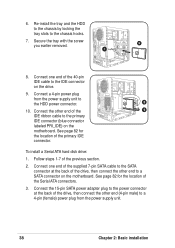
...one end of the supplied 7-pin SATA cable to the SATA connector at the back of the 9 IDE ribbon cable to a SATA connector on the motherboard. Connect the other end to the primary IDE connector (blue connector labeled PRI_IDE) on the drive. 9. Connect the 15-pin SATA power adapter plug to... ATA hard disk drive: 1. Re-install the tray and the HDD to the chassis by locking the tray slots to the IDE connector on the motherboard. Follow steps 1-7 of the Serial ATA connectors. 3. Secure the tray with the screw 6 you earlier removed. 7 8. See page 82 for the location of the ...
...one end of the supplied 7-pin SATA cable to the SATA connector at the back of the 9 IDE ribbon cable to a SATA connector on the motherboard. Connect the other end to the primary IDE connector (blue connector labeled PRI_IDE) on the drive. 9. Connect the 15-pin SATA power adapter plug to... ATA hard disk drive: 1. Re-install the tray and the HDD to the chassis by locking the tray slots to the IDE connector on the motherboard. Follow steps 1-7 of the Serial ATA connectors. 3. Secure the tray with the screw 6 you earlier removed. 7 8. See page 82 for the location of the ...
T2-P User Manual
Page 46
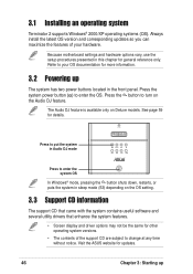
Because motherboard settings and hardware options vary, use the setup procedures presented in the front panel. Press the button to turn on Deluxe models. The Audio DJ ... Refer to change at any time without notice. Press to put the system in Audio DJ mode MODE Press to enter the OS. Visit the ASUS website for updates. 46 Chapter 3: Starting up The system has two power buttons located in this chapter for details. See page 59 for general reference...
Because motherboard settings and hardware options vary, use the setup procedures presented in the front panel. Press the button to turn on Deluxe models. The Audio DJ ... Refer to change at any time without notice. Press to put the system in Audio DJ mode MODE Press to enter the OS. Visit the ASUS website for updates. 46 Chapter 3: Starting up The system has two power buttons located in this chapter for details. See page 59 for general reference...
T2-P User Manual
Page 48
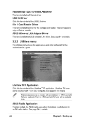
... application. See page 58 for details. 48 Chapter 3: Starting up ASUS Radio Application This item installs the ASUS radio application that the motherboard supports. LifeView TV tuner allows you to an FM radio station. ASUS Wireless LAN Adapter Driver This item installs the ASUS wireless LAN driver. This item appears only on Deluxe models. See...
... application. See page 58 for details. 48 Chapter 3: Starting up ASUS Radio Application This item installs the ASUS radio application that the motherboard supports. LifeView TV tuner allows you to an FM radio station. ASUS Wireless LAN Adapter Driver This item installs the ASUS wireless LAN driver. This item appears only on Deluxe models. See...
T2-P User Manual
Page 49
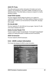
...any detected problems. This utility helps you to update the motherboard BIOS and drivers. View the PC-cillin online help for details. ASUS Terminator 2 barebone system 49 Install ASUS Update This item installs the ASUS Update that allows you keep your computer in Portable Document ... network or an Internet Service Provider (ISP). See page 95 for detailed information. ASUS Screensaver This item installs the ASUS Screensaver. 3.3.4 ASUS contact information The Contact tab displays the ASUS contact information. PC-CILLIN 2002 This item installs the PC-cillin 2002 anti-virus program...
...any detected problems. This utility helps you to update the motherboard BIOS and drivers. View the PC-cillin online help for details. ASUS Terminator 2 barebone system 49 Install ASUS Update This item installs the ASUS Update that allows you keep your computer in Portable Document ... network or an Internet Service Provider (ISP). See page 95 for detailed information. ASUS Screensaver This item installs the ASUS Screensaver. 3.3.4 ASUS contact information The Contact tab displays the ASUS contact information. PC-CILLIN 2002 This item installs the PC-cillin 2002 anti-virus program...
T2-P User Manual
Page 50
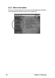
3.3.5 Other information The icons on the top right side of the screen provide additional information on the motherboard and the contents of the support CD. 50 Chapter 3: Starting up
3.3.5 Other information The icons on the top right side of the screen provide additional information on the motherboard and the contents of the support CD. 50 Chapter 3: Starting up


