
User Manual
Page 1
R SP97-XV Pentium® ATX Motherboard USER'S MANUAL
R SP97-XV Pentium® ATX Motherboard USER'S MANUAL
User Manual
Page 2
...SUBJECT TO CHANGE AT ANY TIME WITHOUT NOTICE, AND SHOULD NOT BE CONSTRUED AS A COMMITMENT BY ASUS. Product Name: ASUS SP97-XV Manual Revision: 1.02 Release Date: October 1997 2 ASUS SP97-XV User's Manual ASUS PROVIDES THIS MANUAL "AS IS" WITHOUT WARRANTY OF ANY KIND, EITHER EXPRESS OR IMPLIED, INCLUDING...or altered, unless such repair, modification of the manual revision number. Product warranty or service will not be extended if: (1) the motherboard is authorized in writing by the third digit in it, may not be reproduced, transmitted, transcribed, stored in a retrieval system, ...
...SUBJECT TO CHANGE AT ANY TIME WITHOUT NOTICE, AND SHOULD NOT BE CONSTRUED AS A COMMITMENT BY ASUS. Product Name: ASUS SP97-XV Manual Revision: 1.02 Release Date: October 1997 2 ASUS SP97-XV User's Manual ASUS PROVIDES THIS MANUAL "AS IS" WITHOUT WARRANTY OF ANY KIND, EITHER EXPRESS OR IMPLIED, INCLUDING...or altered, unless such repair, modification of the manual revision number. Product warranty or service will not be extended if: (1) the motherboard is authorized in writing by the third digit in it, may not be reproduced, transmitted, transcribed, stored in a retrieval system, ...
User Manual
Page 4
... Memory (SIMM & DIMM 17 SIMM Memory Installation 18 DIMM Memory Installation Procedures 19 3. External Connectors 24 Power Connection Procedures 31 IV. INSTALLATION 10 ASUS SP97-XV Motherboard Layout 10 Installation Steps 12 1. Jumpers 12 Jumper Settings 13 2. Central Processing Unit (CPU 21 4. Expansion Cards 22 Expansion Card Installation Procedure 22... Setup 41 Power Management Setup 44 Details of Power Management Setup 44 PNP and PCI Setup 46 Details of the ASUS SP97-XV Motherboard 9 III. INTRODUCTION 7 How this manual is organized 7 Item Checklist 7 II.
... Memory (SIMM & DIMM 17 SIMM Memory Installation 18 DIMM Memory Installation Procedures 19 3. External Connectors 24 Power Connection Procedures 31 IV. INSTALLATION 10 ASUS SP97-XV Motherboard Layout 10 Installation Steps 12 1. Jumpers 12 Jumper Settings 13 2. Central Processing Unit (CPU 21 4. Expansion Cards 22 Expansion Card Installation Procedure 22... Setup 41 Power Management Setup 44 Details of Power Management Setup 44 PNP and PCI Setup 46 Details of the ASUS SP97-XV Motherboard 9 III. INTRODUCTION 7 How this manual is organized 7 Item Checklist 7 II.
User Manual
Page 7
...SCSI card (optional) ASUS SP97-XV User's Manual 7 Installation: Instructions on setting up the BIOS software V. BIOS Software: Instructions on the included support software VI. INTRODUCTION How this product III. Support Software: Information on setting up the motherboard IV. I .... If you discover damaged or missing items, please contact your retailer. (1) ASUS Motherboard (1) IDE ribbon cable for master and slave drives (1) Floppy ribbon cable for (1)...
...SCSI card (optional) ASUS SP97-XV User's Manual 7 Installation: Instructions on setting up the BIOS software V. BIOS Software: Instructions on the included support software VI. INTRODUCTION How this product III. Support Software: Information on setting up the motherboard IV. I .... If you discover damaged or missing items, please contact your retailer. (1) ASUS Motherboard (1) IDE ribbon cable for master and slave drives (1) Floppy ribbon cable for (1)...

User Manual
Page 8
... controller cards through BIOS, which allows hardware to communicate within a standard protocol creating a higher level of the ASUS SP97-XV Motherboard The ASUS SP97-XV motherboard is carefully designed for greater support. 8 ASUS SP97-XV User's Manual Supports Japanese "Floppy 3 mode" (3.5-inch disk drive: 1.2MB) and LS-120 floppy disk drives (3.5-inch disk drive: 120 MB, 1.44MB, 720K). BIOS supports ...
... controller cards through BIOS, which allows hardware to communicate within a standard protocol creating a higher level of the ASUS SP97-XV Motherboard The ASUS SP97-XV motherboard is carefully designed for greater support. 8 ASUS SP97-XV User's Manual Supports Japanese "Floppy 3 mode" (3.5-inch disk drive: 1.2MB) and LS-120 floppy disk drives (3.5-inch disk drive: 120 MB, 1.44MB, 720K). BIOS supports ...

User Manual
Page 9
B: Serial Conn. FEATURES Parts of the ASUS SP97-XV Motherboard T: PS/2 Mouse B: PS/2 Keyboard T: USB Port 1 B: USB Port 2 COM 1 2 DIMM Sockets CPU ZIF Socket 7 T: Parallel Conn. COM 2 512KB Pipelined Burst L2 Cache SiS5582 or SiS5598 (VGA) Chipset 4 PCI Slots Multi-I/O 4 ISA Slots Programmable Flash ROM ASUS SP97-XV User's Manual 9 II. FEATURES (Motherboard Parts) II.
B: Serial Conn. FEATURES Parts of the ASUS SP97-XV Motherboard T: PS/2 Mouse B: PS/2 Keyboard T: USB Port 1 B: USB Port 2 COM 1 2 DIMM Sockets CPU ZIF Socket 7 T: Parallel Conn. COM 2 512KB Pipelined Burst L2 Cache SiS5582 or SiS5598 (VGA) Chipset 4 PCI Slots Multi-I/O 4 ISA Slots Programmable Flash ROM ASUS SP97-XV User's Manual 9 II. FEATURES (Motherboard Parts) II.

User Manual
Page 10
INSTALLATION ASUS SP97-XV Motherboard Layout PS/2 MOUSE (TOP PORT) KEYBOARD (BOTTOM) USB USB 1(TOP PORT) USB 2 (BOTTOM) PWR_FAN VGA_SEL ...ISA Slot 3 Flash EEPROM (Programable BIOS) CHA_FAN CMOS Power CR2032 3 Volt Cell RTCLR IrDA IDE LED Secondary IDE Primary IDE ISA Slot 4 Panel Conn. INSTALLATION (Motherboard Layout) CPU_FAN COM 2 Row 3 2 3 2 1 0 1 0 BUS Ratio FS0 FS1 FS2 Row 3 2 1 0 BUS Freq. III. BF0 BF1 BF2... 4 ISA Slot 1 ISA Slot 2 VGA Feature Conn. NOTE: Outlined components are available only with the onboard VGA version. 10 ASUS SP97-XV User's Manual
INSTALLATION ASUS SP97-XV Motherboard Layout PS/2 MOUSE (TOP PORT) KEYBOARD (BOTTOM) USB USB 1(TOP PORT) USB 2 (BOTTOM) PWR_FAN VGA_SEL ...ISA Slot 3 Flash EEPROM (Programable BIOS) CHA_FAN CMOS Power CR2032 3 Volt Cell RTCLR IrDA IDE LED Secondary IDE Primary IDE ISA Slot 4 Panel Conn. INSTALLATION (Motherboard Layout) CPU_FAN COM 2 Row 3 2 3 2 1 0 1 0 BUS Ratio FS0 FS1 FS2 Row 3 2 1 0 BUS Freq. III. BF0 BF1 BF2... 4 ISA Slot 1 ISA Slot 2 VGA Feature Conn. NOTE: Outlined components are available only with the onboard VGA version. 10 ASUS SP97-XV User's Manual
User Manual
Page 11
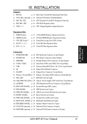
...-pin Blocks) 9) IDE_LED p. 27 IDE LED Activity Light 10) CHA, PWR, CPU_FAN p. 28 Chassis, Power Supply, CPU Fan Power (3-pin Blocks) 11) ATXPWR p. 28 ATX Motherboard Power Connector (20-pin Block) 12) MSG LED (PANEL) p. 29 System Message LED (2 pins) 13) SMI (PANEL) p. 29 SMI Switch Lead (2 pins) 14) PWR SW... (PANEL) p. 29 Speaker Output Connector (4 pins) 19) VGACON (optional) p. 30 Onboard VGA Connector (16 pins) 20) FEATURE (optional) p. 30 Onboard VGA Feature Connector (26 pins) ASUS SP97-XV User's Manual 11 INSTALLATION (Map of Board) III. III.
...-pin Blocks) 9) IDE_LED p. 27 IDE LED Activity Light 10) CHA, PWR, CPU_FAN p. 28 Chassis, Power Supply, CPU Fan Power (3-pin Blocks) 11) ATXPWR p. 28 ATX Motherboard Power Connector (20-pin Block) 12) MSG LED (PANEL) p. 29 System Message LED (2 pins) 13) SMI (PANEL) p. 29 SMI Switch Lead (2 pins) 14) PWR SW... (PANEL) p. 29 Speaker Output Connector (4 pins) 19) VGACON (optional) p. 30 Onboard VGA Connector (16 pins) 20) FEATURE (optional) p. 30 Onboard VGA Feature Connector (26 pins) ASUS SP97-XV User's Manual 11 INSTALLATION (Map of Board) III. III.

User Manual
Page 12
... jumper numbers require that came with the keyboard connector away from the system. 12 ASUS SP97-XV User's Manual Hold components by the edges and try not to touch the IC chips, leads or connectors, or other groups. See "Motherboard Layout" for locations of your computer when working on jumpers with two pins will...
... jumper numbers require that came with the keyboard connector away from the system. 12 ASUS SP97-XV User's Manual Hold components by the edges and try not to touch the IC chips, leads or connectors, or other groups. See "Motherboard Layout" for locations of your computer when working on jumpers with two pins will...

User Manual
Page 13
... (RTCLR) You can test the battery's current by this jumper and attaching a current meter to the "Operation" pins. INSTALLATION (Jumpers) ASUS SP97-XV User's Manual 13 You must unplug the power cord to your motherboard. RTC RAM RTCLR Operation [1-2] (Default) Clear Data [2-3] (momentarily) R Real Time Clock (RTC) RAM RTCLR Battery Test RTCLR Operation (Default...
... (RTCLR) You can test the battery's current by this jumper and attaching a current meter to the "Operation" pins. INSTALLATION (Jumpers) ASUS SP97-XV User's Manual 13 You must unplug the power cord to your motherboard. RTC RAM RTCLR Operation [1-2] (Default) Clear Data [2-3] (momentarily) R Real Time Clock (RTC) RAM RTCLR Battery Test RTCLR Operation (Default...

User Manual
Page 14
... the CPU and the External frequency (called the BUS Clock) within your operating system. These must be stable. 14 ASUS SP97-XV User's Manual Frequencies above jumpers CPU External (BUS) Frequency Selection. The motherboard BIOS will automatically Enable or Disable the onboard VGA based on or off if necessary. FS0 FS1 FS2 FS0 FS1...
... the CPU and the External frequency (called the BUS Clock) within your operating system. These must be stable. 14 ASUS SP97-XV User's Manual Frequencies above jumpers CPU External (BUS) Frequency Selection. The motherboard BIOS will automatically Enable or Disable the onboard VGA based on or off if necessary. FS0 FS1 FS2 FS0 FS1...

User Manual
Page 15
Look on this motherboard is supported on the underside of the Intel, AMD, IBM, or Cyrix CPU as follows: CPU Model Intel Pentium P54C Intel Pentium P54C Intel Pentium .../Cyrix 6x86L-PR166+ 133MHz D-2.0x 66MHz [2-3] [1-2] [2-3] [----] [1-2] [2-3] AMD-K6-PR233 AMD-K6-PR200 AMD-K6-PR166 233MHz E-3.5x 66MHz 200MHz E-3.0x 66MHz 166MHz E-2.5x 66MHz [2-3] [1-2] [2-3] [----] [1-2] [1-2] [2-3] [1-2] [2-3] [----] [2-3] [1-2] [2-3] [1-2] [2-3] [----] [2-3] [2-3] III. ASUS SP97-XV User's Manual 15 The number should read G8DC6620A or later.
Look on this motherboard is supported on the underside of the Intel, AMD, IBM, or Cyrix CPU as follows: CPU Model Intel Pentium P54C Intel Pentium P54C Intel Pentium .../Cyrix 6x86L-PR166+ 133MHz D-2.0x 66MHz [2-3] [1-2] [2-3] [----] [1-2] [2-3] AMD-K6-PR233 AMD-K6-PR200 AMD-K6-PR166 233MHz E-3.5x 66MHz 200MHz E-3.0x 66MHz 166MHz E-2.5x 66MHz [2-3] [1-2] [2-3] [----] [1-2] [1-2] [2-3] [1-2] [2-3] [----] [2-3] [1-2] [2-3] [1-2] [2-3] [----] [2-3] [2-3] III. ASUS SP97-XV User's Manual 15 The number should read G8DC6620A or later.

User Manual
Page 17
...) Total Memory x2 x2 Total System Memory (Max 256MB) = WARNING! INSTALLATION 2. SIMMs must be empty) Total System Memory (Max 256MB) Total Memory x1 x1 = ASUS SP97-XV User's Manual 17 Memory Socket SIMM Sockets 1&2 (Rows 0 & 1) SIMM Sockets 3&4 (Rows 2 & 3) SIMM Memory Module 4MB, 8MB, 16MB, 32MB, 64MB ...at the same time or else you will be installed in BIOS Chipset Setup of the SIMM module takes up one Row on the motherboard. Mixing SIMMs and DIMMs require 5.0Volt (signal level) tolerant memory chips which are not supported). IMPORTANT: Memory speed setup is ...
...) Total Memory x2 x2 Total System Memory (Max 256MB) = WARNING! INSTALLATION 2. SIMMs must be empty) Total System Memory (Max 256MB) Total Memory x1 x1 = ASUS SP97-XV User's Manual 17 Memory Socket SIMM Sockets 1&2 (Rows 0 & 1) SIMM Sockets 3&4 (Rows 2 & 3) SIMM Memory Module 4MB, 8MB, 16MB, 32MB, 64MB ...at the same time or else you will be installed in BIOS Chipset Setup of the SIMM module takes up one Row on the motherboard. Mixing SIMMs and DIMMs require 5.0Volt (signal level) tolerant memory chips which are not supported). IMPORTANT: Memory speed setup is ...

User Manual
Page 19
INSTALLATION (System Memory) III. You must be inserted into the DIMM slot on the motherboard. ASUS SP97-XV User's Manual 19 DRAM SIMM modules have a higher pin density. INSTALLATION DIMM Memory Installation Procedures: Insert the module(s) as shown. SDRAM DIMM modules have different...illustration below: 168-Pin DIMM Notch Key Definitions (3.3V) DRAM Key Position RFU Unbuffered Buffered Voltage Key Position 5.0V Reserved 3.3V The notch on this motherboard. You can identify the type of pins are supported on the DIMM module will only fit in the orientation as shown.
INSTALLATION (System Memory) III. You must be inserted into the DIMM slot on the motherboard. ASUS SP97-XV User's Manual 19 DRAM SIMM modules have a higher pin density. INSTALLATION DIMM Memory Installation Procedures: Insert the module(s) as shown. SDRAM DIMM modules have different...illustration below: 168-Pin DIMM Notch Key Definitions (3.3V) DRAM Key Position RFU Unbuffered Buffered Voltage Key Position 5.0V Reserved 3.3V The notch on this motherboard. You can identify the type of pins are supported on the DIMM module will only fit in the orientation as shown.

User Manual
Page 21
... CPU will cover the face of the CPU. The CPU that will only fit in the one hole is backwards compatible with Pentium MMX Processor ASUS SP97-XV User's Manual 21 Insert the CPU with the white dot as shown. you install. III. Use the notched corner of pin holes and a "1"... remove its cover. Locate the ZIF socket and open it to BUS Frequency Ratio" and jumpers for reference only; Central Processing Unit (CPU) The motherboard provides a 321-pin ZIF Socket 7 that you should have a fan attached to it by first pulling the lever sideways away from that corner. ...
... CPU will cover the face of the CPU. The CPU that will only fit in the one hole is backwards compatible with Pentium MMX Processor ASUS SP97-XV User's Manual 21 Insert the CPU with the white dot as shown. you install. III. Use the notched corner of pin holes and a "1"... remove its cover. Locate the ZIF socket and open it to BUS Frequency Ratio" and jumpers for reference only; Central Processing Unit (CPU) The motherboard provides a 321-pin ZIF Socket 7 that you should have a fan attached to it by first pulling the lever sideways away from that corner. ...
User Manual
Page 22
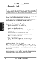
... of the system which allows the installation of a PCI card or a MediaBus card (optional multifunctional card) but most of ISA cards. 22 ASUS SP97-XV User's Manual III. Remove the bracket on any hardware and software settings that you removed in use an IRQ to setup your expansion card. ...there are 16 IRQs available but not both your expansion card documentation on the slot you intend to use by PCI cards. First read your motherboard and expansion cards. Set any remaining IRQs are two types of them are available to one use . Remove your expansion card. 2. sible...
... of the system which allows the installation of a PCI card or a MediaBus card (optional multifunctional card) but most of ISA cards. 22 ASUS SP97-XV User's Manual III. Remove the bracket on any hardware and software settings that you removed in use an IRQ to setup your expansion card. ...there are 16 IRQs available but not both your expansion card documentation on the slot you intend to use by PCI cards. First read your motherboard and expansion cards. Set any remaining IRQs are two types of them are available to one use . Remove your expansion card. 2. sible...

User Manual
Page 23
... requires an IRQ. An IRQ number is added to the system. In the PCI bus design, the BIOS automatically assigns an IRQ to reserve). ASUS SP97-XV User's Manual 23 INSTALLATION (Expansion Cards) III. IMPORTANT: To avoid conflicts, reserve the necessary IRQs and DMAs for legacy ISA cards (under PNP... cards after those available. You may also need to as the IRQ assignment process described earlier. Make sure that the jumpers on this motherboard has complied with the BIOS, you configure the card's jumpers manually and then install it that you can contact your vendor for those ...
... requires an IRQ. An IRQ number is added to the system. In the PCI bus design, the BIOS automatically assigns an IRQ to reserve). ASUS SP97-XV User's Manual 23 INSTALLATION (Expansion Cards) III. IMPORTANT: To avoid conflicts, reserve the necessary IRQs and DMAs for legacy ISA cards (under PNP... cards after those available. You may also need to as the IRQ assignment process described earlier. Make sure that the jumpers on this motherboard has complied with the BIOS, you configure the card's jumpers manually and then install it that you can contact your vendor for those ...
User Manual
Page 24
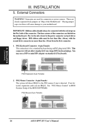
...IDE ribbon cable must be connected with the second drive connector no more than 6in. (15cm) from jumpers in BIOS Features Setup of the Motherboard." PS/2 Keyboard (6-pin Female) 2. INSTALLATION (Connectors) III. This connector will direct IRQ12 to the power connector on the Pin 1 side...standard keyboard using an PS/2 plug (mini DIN). If not detected, expansion cards can use a DIN to your motherboard. You may use IRQ12. PS/2 Mouse (6-pin Female) 24 ASUS SP97-XV User's Manual III. See "PS/2 Mouse Control" in "Map of the BIOS SOFTWARE. Some pins are labeled ...
...IDE ribbon cable must be connected with the second drive connector no more than 6in. (15cm) from jumpers in BIOS Features Setup of the Motherboard." PS/2 Keyboard (6-pin Female) 2. INSTALLATION (Connectors) III. This connector will direct IRQ12 to the power connector on the Pin 1 side...standard keyboard using an PS/2 plug (mini DIN). If not detected, expansion cards can use a DIN to your motherboard. You may use IRQ12. PS/2 Mouse (6-pin Female) 24 ASUS SP97-XV User's Manual III. See "PS/2 Mouse Control" in "Map of the BIOS SOFTWARE. Some pins are labeled ...

User Manual
Page 26
... (NC) IRRX For the infrared feature to be available, you must connect an optional Infrared module to Pin 1 Pin 1 26 ASUS SP97-XV User's Manual After connecting the single end to prevent inserting in the wrong orientation when using ribbon cables with pin 5 plugged). This... on system cases that support this feature. INSTALLATION (Connectors) III. INSTALLATION 6. Floppy Disk Drive Connector NOTE: Orient the red stripe to the motherboard. 7. Floppy Disk Drive Connector (34-1pin FLOPPY) This connector supports the provided floppy drive ribbon cable. R R III. IrDA / Fast ...
... (NC) IRRX For the infrared feature to be available, you must connect an optional Infrared module to Pin 1 Pin 1 26 ASUS SP97-XV User's Manual After connecting the single end to prevent inserting in the wrong orientation when using ribbon cables with pin 5 plugged). This... on system cases that support this feature. INSTALLATION (Connectors) III. INSTALLATION 6. Floppy Disk Drive Connector NOTE: Orient the red stripe to the motherboard. 7. Floppy Disk Drive Connector (34-1pin FLOPPY) This connector supports the provided floppy drive ribbon cable. R R III. IrDA / Fast ...

User Manual
Page 30
... and mount the bracket to save expansion slot space. 20. VGA Connector (VGACON, 16 pins) (with onboard VGA version only) This connector, available only on motherboards with the SiS5598 chipset, supports the provided video or monitor cable with pin 1 15 VGA (Monitor) Connector Bracket to end approximately 6inch TIP: You may... only) This connector is used for third-party video accessories such as video capture cards or television tuners. 14 1 Video Feature Connector 26 13 30 ASUS SP97-XV User's Manual INSTALLATION 19.
... and mount the bracket to save expansion slot space. 20. VGA Connector (VGACON, 16 pins) (with onboard VGA version only) This connector, available only on motherboards with the SiS5598 chipset, supports the provided video or monitor cable with pin 1 15 VGA (Monitor) Connector Bracket to end approximately 6inch TIP: You may... only) This connector is used for third-party video accessories such as video capture cards or television tuners. 14 1 Video Feature Connector 26 13 30 ASUS SP97-XV User's Manual INSTALLATION 19.


