
User Manual
Page 1
R SP97-XV Pentium® ATX Motherboard USER'S MANUAL
R SP97-XV Pentium® ATX Motherboard USER'S MANUAL
User Manual
Page 2
... for each board design represented by the digit before and after the period of the manual revision number. Product Name: ASUS SP97-XV Manual Revision: 1.02 Release Date: October 1997 2 ASUS SP97-XV User's Manual or (2) the serial number of the product is a registered trademark of Symbios Logic Corporation... • Adobe and Acrobat are represented by the third digit in writing by ASUS; Manual updates are registered trademarks of Adobe Systems Incorporated. All Rights Reserved. ASUS PROVIDES THIS MANUAL "AS IS" WITHOUT WARRANTY OF ANY KIND, EITHER EXPRESS OR IMPLIED, INCLUDING BUT...
... for each board design represented by the digit before and after the period of the manual revision number. Product Name: ASUS SP97-XV Manual Revision: 1.02 Release Date: October 1997 2 ASUS SP97-XV User's Manual or (2) the serial number of the product is a registered trademark of Symbios Logic Corporation... • Adobe and Acrobat are represented by the third digit in writing by ASUS; Manual updates are registered trademarks of Adobe Systems Incorporated. All Rights Reserved. ASUS PROVIDES THIS MANUAL "AS IS" WITHOUT WARRANTY OF ANY KIND, EITHER EXPRESS OR IMPLIED, INCLUDING BUT...

User Manual
Page 3
... Technical Support Fax: +886-2-895-9254 BBS: +886-2-896-4667 Email: tsd@asus.com.tw WWW: www.asus.com.tw Gopher: gopher.asus.com.tw FTP: ftp.asus.com.tw/pub/ASUS ASUS COMPUTER INTERNATIONAL Marketing Info Address: 721 Charcot Avenue, San Jose, CA 95131, USA...asus.com.tw WWW: www.asus.com ASUS COMPUTER GmbH Marketing Info Address: Harkort Str. 25, 40880 Ratingen, BRD, Germany Telephone: 49-2102-445011 Fax: 49-2102-442066 Email: info-ger@asus.com.tw Technical Support BBS: 49-2102-448690 Email: tsd-ger@asus.com.tw Hotline: 49-2102-499712 ASUS SP97-XV User's Manual...
... Technical Support Fax: +886-2-895-9254 BBS: +886-2-896-4667 Email: tsd@asus.com.tw WWW: www.asus.com.tw Gopher: gopher.asus.com.tw FTP: ftp.asus.com.tw/pub/ASUS ASUS COMPUTER INTERNATIONAL Marketing Info Address: 721 Charcot Avenue, San Jose, CA 95131, USA...asus.com.tw WWW: www.asus.com ASUS COMPUTER GmbH Marketing Info Address: Harkort Str. 25, 40880 Ratingen, BRD, Germany Telephone: 49-2102-445011 Fax: 49-2102-442066 Email: info-ger@asus.com.tw Technical Support BBS: 49-2102-448690 Email: tsd-ger@asus.com.tw Hotline: 49-2102-499712 ASUS SP97-XV User's Manual...
User Manual
Page 4
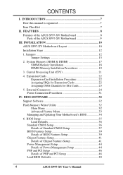
... 22 Expansion Card Installation Procedure 22 Assigning IRQs for Expansion Cards 22 Assigning DMA Channels for ISA Cards 23 5. INSTALLATION 10 ASUS SP97-XV Motherboard Layout 10 Installation Steps 12 1. Central Processing Unit (CPU 21 4. BIOS Setup 35 Load Defaults 36 Standard CMOS Setup... System Memory (SIMM & DIMM 17 SIMM Memory Installation 18 DIMM Memory Installation Procedures 19 3. INTRODUCTION 7 How this manual is organized 7 Item Checklist 7 II. FEATURES 8 Features of the ASUS SP97-XV Motherboard 8 Parts of PNP and PCI Setup 46 Load BIOS Defaults 48...
... 22 Expansion Card Installation Procedure 22 Assigning IRQs for Expansion Cards 22 Assigning DMA Channels for ISA Cards 23 5. INSTALLATION 10 ASUS SP97-XV Motherboard Layout 10 Installation Steps 12 1. Central Processing Unit (CPU 21 4. BIOS Setup 35 Load Defaults 36 Standard CMOS Setup... System Memory (SIMM & DIMM 17 SIMM Memory Installation 18 DIMM Memory Installation Procedures 19 3. INTRODUCTION 7 How this manual is organized 7 Item Checklist 7 II. FEATURES 8 Features of the ASUS SP97-XV Motherboard 8 Parts of PNP and PCI Setup 46 Load BIOS Defaults 48...
User Manual
Page 5
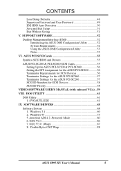
... Configuration Utility 53 Notes 53 VI. Windows 3.1 69 2. Windows 95 75 5. Double Bytes OS/2 Warp 88 ASUS SP97-XV User's Manual 5 CONTENTS Load Setup Defaults 48 Supervisor Password and User Password 49 IDE HDD Auto Detection 50 Save and Exit Setup 51 Exit Without Saving ...56 Setting the INT Assignment for the ASUS PCI-SC200 56 Terminator Requirements for SCSI Devices 56 Terminator Settings for the ASUS PCI-SC860 57 Terminator Settings for the ASUS PCI-SC200 57 SCSI ID Numbers for SCSI Devices 58 SCSI ID Priority 58 VIDEO SOFTWARE USER'S MANUAL (with onboard VGA) .. 59 VIII...
... Configuration Utility 53 Notes 53 VI. Windows 3.1 69 2. Windows 95 75 5. Double Bytes OS/2 Warp 88 ASUS SP97-XV User's Manual 5 CONTENTS Load Setup Defaults 48 Supervisor Password and User Password 49 IDE HDD Auto Detection 50 Save and Exit Setup 51 Exit Without Saving ...56 Setting the INT Assignment for the ASUS PCI-SC200 56 Terminator Requirements for SCSI Devices 56 Terminator Settings for the ASUS PCI-SC860 57 Terminator Settings for the ASUS PCI-SC200 57 SCSI ID Numbers for SCSI Devices 58 SCSI ID Priority 58 VIDEO SOFTWARE USER'S MANUAL (with onboard VGA) .. 59 VIII...

User Manual
Page 6
... This device complies with FCC regulations. However, there is connected. • Consult the dealer or an experienced radio/TV technician for connection of Communications. 6 ASUS SP97-XV User's Manual If this unit not expressly approved by one or more of the following two conditions: • This device may not cause harmful interference, and •...
... This device complies with FCC regulations. However, there is connected. • Consult the dealer or an experienced radio/TV technician for connection of Communications. 6 ASUS SP97-XV User's Manual If this unit not expressly approved by one or more of the following two conditions: • This device may not cause harmful interference, and •...
User Manual
Page 7
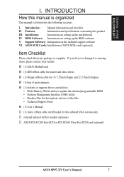
... onboard VGA version only external infrared (IrDA) module (optional) ASUS PCI-SC200 Fast-SCSI or PCI-SC860 Ultra-Fast SCSI card (optional) ASUS SP97-XV User's Manual 7 Features: Information and specifications concerning this manual is organized This manual is complete. Support Software: Information on setting up the motherboard ... sections: I. BIOS Software: Instructions on the included support software VI. I . INTRODUCTION How this product III. Introduction: Manual information and checklist II. Installation: Instructions on setting up the BIOS software V. INTRODUCTION...
... onboard VGA version only external infrared (IrDA) module (optional) ASUS PCI-SC200 Fast-SCSI or PCI-SC860 Ultra-Fast SCSI card (optional) ASUS SP97-XV User's Manual 7 Features: Information and specifications concerning this manual is organized This manual is complete. Support Software: Information on setting up the motherboard ... sections: I. BIOS Software: Instructions on the included support software VI. I . INTRODUCTION How this product III. Introduction: Manual information and checklist II. Installation: Instructions on setting up the BIOS software V. INTRODUCTION...

User Manual
Page 8
...more than 8.4GB in two channels up to communicate within a standard protocol creating a higher level of the ASUS SP97-XV Motherboard The ASUS SP97-XV motherboard is carefully designed for the demanding PC user who wants many features in video controller and supports video ...Memory Support: Is equipped with onboard 512K Pipelined Burst SRAM. • IrDA Connector: Supports an optional infrared module for greater support. 8 ASUS SP97-XV User's Manual Is also equipped with two connectors. II. The SiS5598 chipset has a built-in a small package, namely: • SiS Chipset: ...
...more than 8.4GB in two channels up to communicate within a standard protocol creating a higher level of the ASUS SP97-XV Motherboard The ASUS SP97-XV motherboard is carefully designed for the demanding PC user who wants many features in video controller and supports video ...Memory Support: Is equipped with onboard 512K Pipelined Burst SRAM. • IrDA Connector: Supports an optional infrared module for greater support. 8 ASUS SP97-XV User's Manual Is also equipped with two connectors. II. The SiS5598 chipset has a built-in a small package, namely: • SiS Chipset: ...

User Manual
Page 9
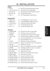
II. B: Serial Conn. COM 2 512KB Pipelined Burst L2 Cache SiS5582 or SiS5598 (VGA) Chipset 4 PCI Slots Multi-I/O 4 ISA Slots Programmable Flash ROM ASUS SP97-XV User's Manual 9 FEATURES Parts of the ASUS SP97-XV Motherboard T: PS/2 Mouse B: PS/2 Keyboard T: USB Port 1 B: USB Port 2 COM 1 2 DIMM Sockets CPU ZIF Socket 7 T: Parallel Conn. FEATURES (Motherboard Parts) II.
II. B: Serial Conn. COM 2 512KB Pipelined Burst L2 Cache SiS5582 or SiS5598 (VGA) Chipset 4 PCI Slots Multi-I/O 4 ISA Slots Programmable Flash ROM ASUS SP97-XV User's Manual 9 FEATURES Parts of the ASUS SP97-XV Motherboard T: PS/2 Mouse B: PS/2 Keyboard T: USB Port 1 B: USB Port 2 COM 1 2 DIMM Sockets CPU ZIF Socket 7 T: Parallel Conn. FEATURES (Motherboard Parts) II.

User Manual
Page 10
INSTALLATION ASUS SP97-XV Motherboard Layout PS/2 MOUSE (TOP PORT) KEYBOARD (BOTTOM) USB USB 1(TOP PORT) USB 2 (BOTTOM) PWR_FAN VGA_SEL Board Power Input for ATX Power Supply CPU Voltage ... (Motherboard Layout) CPU_FAN COM 2 Row 3 2 3 2 1 0 1 0 BUS Ratio FS0 FS1 FS2 Row 3 2 1 0 BUS Freq. NOTE: Outlined components are available only with the onboard VGA version. 10 ASUS SP97-XV User's Manual
INSTALLATION ASUS SP97-XV Motherboard Layout PS/2 MOUSE (TOP PORT) KEYBOARD (BOTTOM) USB USB 1(TOP PORT) USB 2 (BOTTOM) PWR_FAN VGA_SEL Board Power Input for ATX Power Supply CPU Voltage ... (Motherboard Layout) CPU_FAN COM 2 Row 3 2 3 2 1 0 1 0 BUS Ratio FS0 FS1 FS2 Row 3 2 1 0 BUS Freq. NOTE: Outlined components are available only with the onboard VGA version. 10 ASUS SP97-XV User's Manual
User Manual
Page 11
... (PANEL) p. 29 Speaker Output Connector (4 pins) 19) VGACON (optional) p. 30 Onboard VGA Connector (16 pins) 20) FEATURE (optional) p. 30 Onboard VGA Feature Connector (26 pins) ASUS SP97-XV User's Manual 11
... (PANEL) p. 29 Speaker Output Connector (4 pins) 19) VGACON (optional) p. 30 Onboard VGA Connector (16 pins) 20) FEATURE (optional) p. 30 Onboard VGA Feature Connector (26 pins) ASUS SP97-XV User's Manual 11

User Manual
Page 12
... 1 erboards is written besides pin 1 on the board. Settings with two jumper numbers require that came with the keyboard connector away from the system. 12 ASUS SP97-XV User's Manual To connect the pins, simply place a plastic jumper cap over the two pins as SCSI cards, contain very delicate Integrated Circuit (IC) chips. Unplug... a grounded antistatic pad or on the motherboard. Setup the BIOS Software 1. Jumpers with three pins. For manufacturing simplicity, the jump- Use the diagrams in this manual instead of jumpers. III.
... 1 erboards is written besides pin 1 on the board. Settings with two jumper numbers require that came with the keyboard connector away from the system. 12 ASUS SP97-XV User's Manual To connect the pins, simply place a plastic jumper cap over the two pins as SCSI cards, contain very delicate Integrated Circuit (IC) chips. Unplug... a grounded antistatic pad or on the motherboard. Setup the BIOS Software 1. Jumpers with three pins. For manufacturing simplicity, the jump- Use the diagrams in this manual instead of jumpers. III.

User Manual
Page 13
... powered by this jumper and attaching a current meter to your power supply to ensure that there is no power to the "Operation" pins. INSTALLATION (Jumpers) ASUS SP97-XV User's Manual 13 III.
... powered by this jumper and attaching a current meter to your power supply to ensure that there is no power to the "Operation" pins. INSTALLATION (Jumpers) ASUS SP97-XV User's Manual 13 III.

User Manual
Page 14
...). CPU to be set the frequency ratio between the onboard VGA and a separate installed VGA expansion card within the CPU. These must be stable. 14 ASUS SP97-XV User's Manual The BUS Clock times the BUS Ratio equals the CPU's Internal frequency (the advertised CPU speed). 4. VGA_SEL Enable Disable Setting [2-3] (default) [1-2] VGA_SEL VGA_SEL Enable...
...). CPU to be set the frequency ratio between the onboard VGA and a separate installed VGA expansion card within the CPU. These must be stable. 14 ASUS SP97-XV User's Manual The BUS Clock times the BUS Ratio equals the CPU's Internal frequency (the advertised CPU speed). 4. VGA_SEL Enable Disable Setting [2-3] (default) [1-2] VGA_SEL VGA_SEL Enable...

User Manual
Page 15
Look on this motherboard is rev 2.7 or later. ASUS SP97-XV User's Manual 15 INSTALLATION (Jumpers) *NOTE: The only IBM/Cyrix 6x86(L) (or M1) that is supported on the underside of the Intel, AMD, IBM, or Cyrix CPU ...
Look on this motherboard is rev 2.7 or later. ASUS SP97-XV User's Manual 15 INSTALLATION (Jumpers) *NOTE: The only IBM/Cyrix 6x86(L) (or M1) that is supported on the underside of the Intel, AMD, IBM, or Cyrix CPU ...

User Manual
Page 16
... CPU documentation for your CPU. VID0 VID1 VID2 VID0 VID1 VID2 VID0 VID1 VID2 R III. INSTALLATION 5. Always refer to be true for two voltages. 16 ASUS SP97-XV User's Manual
... CPU documentation for your CPU. VID0 VID1 VID2 VID0 VID1 VID2 VID0 VID1 VID2 R III. INSTALLATION 5. Always refer to be true for two voltages. 16 ASUS SP97-XV User's Manual

User Manual
Page 17
..., 8MB, 16MB, 32MB, 64MB 72-pin FPM or EDO SIMM (DIMM Sockets must be empty) Total System Memory (Max 256MB) Total Memory x1 x1 = ASUS SP97-XV User's Manual 17 INSTALLATION (System Memory) III. Mixing SIMMs and DIMMs require 5.0Volt (signal level) tolerant memory chips which are not used when the SIMM sockets are...
..., 8MB, 16MB, 32MB, 64MB 72-pin FPM or EDO SIMM (DIMM Sockets must be empty) Total System Memory (Max 256MB) Total Memory x1 x1 = ASUS SP97-XV User's Manual 17 INSTALLATION (System Memory) III. Mixing SIMMs and DIMMs require 5.0Volt (signal level) tolerant memory chips which are not used when the SIMM sockets are...
User Manual
Page 18
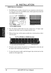
... memory module into place. Clip 72 Pin DRAM in one end of the SIMM sockets, which requires the notched end of the support clips. 18 ASUS SP97-XV User's Manual R III. INSTALLATION SIMM Memory Installation 1. To release the memory module, push both support clips outward and rock the module out of the SIMM memory...
... memory module into place. Clip 72 Pin DRAM in one end of the SIMM sockets, which requires the notched end of the support clips. 18 ASUS SP97-XV User's Manual R III. INSTALLATION SIMM Memory Installation 1. To release the memory module, push both support clips outward and rock the module out of the SIMM memory...

User Manual
Page 19
... 88 Pins Lock 168 Pin DIMM Memory Sockets The Dual Inline Memory Module (DIMM) memory modules must ask your retailer for the specifications before purchasing. ASUS SP97-XV User's Manual 19 III. INSTALLATION DIMM Memory Installation Procedures: Insert the module(s) as shown. DRAM SIMM modules have a higher pin density. Four clock signals are different...
... 88 Pins Lock 168 Pin DIMM Memory Sockets The Dual Inline Memory Module (DIMM) memory modules must ask your retailer for the specifications before purchasing. ASUS SP97-XV User's Manual 19 III. INSTALLATION DIMM Memory Installation Procedures: Insert the module(s) as shown. DRAM SIMM modules have a higher pin density. Four clock signals are different...

User Manual
Page 20
III. INSTALLATION (This page was intentionally left blank) 20 ASUS SP97-XV User's Manual
III. INSTALLATION (This page was intentionally left blank) 20 ASUS SP97-XV User's Manual


