
User Manual
Page 1
R SP97-XV Pentium® ATX Motherboard USER'S MANUAL
R SP97-XV Pentium® ATX Motherboard USER'S MANUAL
User Manual
Page 2
...Manual updates are both printed on the following page. or (2) the serial number of the product is authorized in writing by ASUS; All Rights Reserved. Products and corporate names appearing in this manual, including the products and software described in it, may ...or service will not be extended if: (1) the motherboard is repaired, modified or altered, unless such repair, modification of alteration is defaced or missing. Product Name: ASUS SP97-XV Manual Revision: 1.02 Release Date: October 1997 2 ASUS SP97-XV User's Manual ASUS PROVIDES THIS MANUAL "AS IS" WITHOUT WARRANTY OF...
...Manual updates are both printed on the following page. or (2) the serial number of the product is authorized in writing by ASUS; All Rights Reserved. Products and corporate names appearing in this manual, including the products and software described in it, may ...or service will not be extended if: (1) the motherboard is repaired, modified or altered, unless such repair, modification of alteration is defaced or missing. Product Name: ASUS SP97-XV Manual Revision: 1.02 Release Date: October 1997 2 ASUS SP97-XV User's Manual ASUS PROVIDES THIS MANUAL "AS IS" WITHOUT WARRANTY OF...
User Manual
Page 4
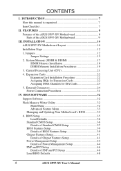
...Features Setup 41 Power Management Setup 44 Details of Power Management Setup 44 PNP and PCI Setup 46 Details of the ASUS SP97-XV Motherboard 9 III. External Connectors 24 Power Connection Procedures 31 IV. BIOS SOFTWARE 32 Support Software 32 Flash Memory Writer ...Advanced Feature Menu 33 Managing and Updating Your Motherboard's BIOS 34 6. INTRODUCTION 7 How this manual is organized 7 Item Checklist 7 II. FEATURES 8 Features of the ASUS SP97-XV Motherboard 8 Parts of PNP and PCI Setup 46 Load BIOS Defaults 48 4 ASUS SP97-XV User's Manual System Memory (SIMM & ...
...Features Setup 41 Power Management Setup 44 Details of Power Management Setup 44 PNP and PCI Setup 46 Details of the ASUS SP97-XV Motherboard 9 III. External Connectors 24 Power Connection Procedures 31 IV. BIOS SOFTWARE 32 Support Software 32 Flash Memory Writer ...Advanced Feature Menu 33 Managing and Updating Your Motherboard's BIOS 34 6. INTRODUCTION 7 How this manual is organized 7 Item Checklist 7 II. FEATURES 8 Features of the ASUS SP97-XV Motherboard 8 Parts of PNP and PCI Setup 46 Load BIOS Defaults 48 4 ASUS SP97-XV User's Manual System Memory (SIMM & ...
User Manual
Page 7
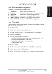
...up the BIOS software V. BIOS Software: Instructions on setting up the motherboard IV. Introduction: Manual information and checklist II. If you discover damaged or missing items, please contact your retailer. (1) ASUS Motherboard (1) IDE ribbon cable for master and slave drives (1) Floppy ribbon...the onboard VGA version only external infrared (IrDA) module (optional) ASUS PCI-SC200 Fast-SCSI or PCI-SC860 Ultra-Fast SCSI card (optional) ASUS SP97-XV User's Manual 7 INTRODUCTION How this product III. ASUS SCSI Cards: Installation of the files • Technical Support Form ...
...up the BIOS software V. BIOS Software: Instructions on setting up the motherboard IV. Introduction: Manual information and checklist II. If you discover damaged or missing items, please contact your retailer. (1) ASUS Motherboard (1) IDE ribbon cable for master and slave drives (1) Floppy ribbon...the onboard VGA version only external infrared (IrDA) module (optional) ASUS PCI-SC200 Fast-SCSI or PCI-SC860 Ultra-Fast SCSI card (optional) ASUS SP97-XV User's Manual 7 INTRODUCTION How this product III. ASUS SCSI Cards: Installation of the files • Technical Support Form ...

User Manual
Page 8
... SRAM. • IrDA Connector: Supports an optional infrared module for wireless interface. • Symbios SCSI BIOS: Supports optional ASUS SCSI controller cards through BIOS, which allows hardware to 256MB. Supports two of either SiS5582 or SiS5598 chipsets. Supports Japanese "...features in two channels up to communicate within a standard protocol creating a higher level of the ASUS SP97-XV Motherboard The ASUS SP97-XV motherboard is carefully designed for greater support. 8 ASUS SP97-XV User's Manual Also supports PIO Modes 3 and 4 and Bus Master IDE DMA Mode 2. FEATURES (Features...
... SRAM. • IrDA Connector: Supports an optional infrared module for wireless interface. • Symbios SCSI BIOS: Supports optional ASUS SCSI controller cards through BIOS, which allows hardware to 256MB. Supports two of either SiS5582 or SiS5598 chipsets. Supports Japanese "...features in two channels up to communicate within a standard protocol creating a higher level of the ASUS SP97-XV Motherboard The ASUS SP97-XV motherboard is carefully designed for greater support. 8 ASUS SP97-XV User's Manual Also supports PIO Modes 3 and 4 and Bus Master IDE DMA Mode 2. FEATURES (Features...

User Manual
Page 9
FEATURES (Motherboard Parts) II. COM 2 512KB Pipelined Burst L2 Cache SiS5582 or SiS5598 (VGA) Chipset 4 PCI Slots Multi-I/O 4 ISA Slots Programmable Flash ROM ASUS SP97-XV User's Manual 9 B: Serial Conn. FEATURES Parts of the ASUS SP97-XV Motherboard T: PS/2 Mouse B: PS/2 Keyboard T: USB Port 1 B: USB Port 2 COM 1 2 DIMM Sockets CPU ZIF Socket 7 T: Parallel Conn. II.
FEATURES (Motherboard Parts) II. COM 2 512KB Pipelined Burst L2 Cache SiS5582 or SiS5598 (VGA) Chipset 4 PCI Slots Multi-I/O 4 ISA Slots Programmable Flash ROM ASUS SP97-XV User's Manual 9 B: Serial Conn. FEATURES Parts of the ASUS SP97-XV Motherboard T: PS/2 Mouse B: PS/2 Keyboard T: USB Port 1 B: USB Port 2 COM 1 2 DIMM Sockets CPU ZIF Socket 7 T: Parallel Conn. II.

User Manual
Page 10
INSTALLATION ASUS SP97-XV Motherboard Layout PS/2 MOUSE (TOP PORT) KEYBOARD (BOTTOM) USB USB 1(TOP PORT) USB 2 (BOTTOM) PWR_FAN VGA_SEL Board Power Input for ATX Power Supply CPU Voltage VID0 ...: Outlined components are available only with the onboard VGA version. 10 ASUS SP97-XV User's Manual ISA Slot 3 Flash EEPROM (Programable BIOS) CHA_FAN CMOS Power CR2032 3 Volt Cell RTCLR IrDA IDE LED Secondary IDE Primary IDE ISA Slot 4 Panel Conn. III. INSTALLATION (Motherboard Layout) CPU_FAN COM 2 Row 3 2 3 2 1 0 1 0 BUS Ratio FS0 FS1 FS2 Row 3 2 1 0 BUS...
INSTALLATION ASUS SP97-XV Motherboard Layout PS/2 MOUSE (TOP PORT) KEYBOARD (BOTTOM) USB USB 1(TOP PORT) USB 2 (BOTTOM) PWR_FAN VGA_SEL Board Power Input for ATX Power Supply CPU Voltage VID0 ...: Outlined components are available only with the onboard VGA version. 10 ASUS SP97-XV User's Manual ISA Slot 3 Flash EEPROM (Programable BIOS) CHA_FAN CMOS Power CR2032 3 Volt Cell RTCLR IrDA IDE LED Secondary IDE Primary IDE ISA Slot 4 Panel Conn. III. INSTALLATION (Motherboard Layout) CPU_FAN COM 2 Row 3 2 3 2 1 0 1 0 BUS Ratio FS0 FS1 FS2 Row 3 2 1 0 BUS...
User Manual
Page 11
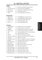
...-pin Blocks) 9) IDE_LED p. 27 IDE LED Activity Light 10) CHA, PWR, CPU_FAN p. 28 Chassis, Power Supply, CPU Fan Power (3-pin Blocks) 11) ATXPWR p. 28 ATX Motherboard Power Connector (20-pin Block) 12) MSG LED (PANEL) p. 29 System Message LED (2 pins) 13) SMI (PANEL) p. 29 SMI Switch Lead (2 pins) 14) PWR SW... (PANEL) p. 29 Speaker Output Connector (4 pins) 19) VGACON (optional) p. 30 Onboard VGA Connector (16 pins) 20) FEATURE (optional) p. 30 Onboard VGA Feature Connector (26 pins) ASUS SP97-XV User's Manual 11 III. INSTALLATION (Map of Board) III.
...-pin Blocks) 9) IDE_LED p. 27 IDE LED Activity Light 10) CHA, PWR, CPU_FAN p. 28 Chassis, Power Supply, CPU Fan Power (3-pin Blocks) 11) ATXPWR p. 28 ATX Motherboard Power Connector (20-pin Block) 12) MSG LED (PANEL) p. 29 System Message LED (2 pins) 13) SMI (PANEL) p. 29 SMI Switch Lead (2 pins) 14) PWR SW... (PANEL) p. 29 Speaker Output Connector (4 pins) 19) VGACON (optional) p. 30 Onboard VGA Connector (16 pins) 20) FEATURE (optional) p. 30 Onboard VGA Feature Connector (26 pins) ASUS SP97-XV User's Manual 11 III. INSTALLATION (Map of Board) III.

User Manual
Page 12
...3. Use the diagrams in this manual instead of jumper caps to a metal object, such as [----], [1-2], [2-3] for Open (Off). Computer motherboards, baseboards and components, such as diagramed. If you do not have one, touch both jumpers be shown as to connect pins 1&2 and ... motherboard with the keyboard connector away from static electricity, you should follow some precautions whenever you must complete the following steps: 1. To protect them against damage from yourself. Install the Central Processing Unit (CPU) 4. ers may be sharing pins from the system. 12 ASUS SP97-XV...
...3. Use the diagrams in this manual instead of jumper caps to a metal object, such as [----], [1-2], [2-3] for Open (Off). Computer motherboards, baseboards and components, such as diagramed. If you do not have one, touch both jumpers be shown as to connect pins 1&2 and ... motherboard with the keyboard connector away from static electricity, you should follow some precautions whenever you must complete the following steps: 1. To protect them against damage from yourself. Install the Central Processing Unit (CPU) 4. ers may be sharing pins from the system. 12 ASUS SP97-XV...

User Manual
Page 13
WARNING! RTC RAM RTCLR Operation [1-2] (Default) Clear Data [2-3] (momentarily) R Real Time Clock (RTC) RAM RTCLR Battery Test RTCLR Operation (Default) Clear Data III. INSTALLATION (Jumpers) ASUS SP97-XV User's Manual 13 To clear the RTC data: (1) Turn off your computer and remove the AC power , (2) Move this jumper and attaching a current meter to ... your power supply to ensure that there is powered by removing this jumper to "Clear Data," (3) Move the jumper back to "Operation," (4) Turn on your motherboard.
WARNING! RTC RAM RTCLR Operation [1-2] (Default) Clear Data [2-3] (momentarily) R Real Time Clock (RTC) RAM RTCLR Battery Test RTCLR Operation (Default) Clear Data III. INSTALLATION (Jumpers) ASUS SP97-XV User's Manual 13 To clear the RTC data: (1) Turn off your computer and remove the AC power , (2) Move this jumper and attaching a current meter to ... your power supply to ensure that there is powered by removing this jumper to "Clear Data," (3) Move the jumper back to "Operation," (4) Turn on your motherboard.

User Manual
Page 14
... allow you have conflicts between the Internal frequency of the CPU's External frequency (or BUS Clock). These must be stable. 14 ASUS SP97-XV User's Manual INSTALLATION (Jumpers) III. You need to disable the onboard VGA only if you to turn the onboard VGA on ...only) These jumpers allow the selection of the CPU and the External frequency (called the BUS Clock) within your operating system. R III. The motherboard BIOS will automatically Enable or Disable the onboard VGA based on or off if necessary. VGA_SEL Enable Disable Setting [2-3] (default) [1-2] VGA_SEL VGA_SEL ...
... allow you have conflicts between the Internal frequency of the CPU's External frequency (or BUS Clock). These must be stable. 14 ASUS SP97-XV User's Manual INSTALLATION (Jumpers) III. You need to disable the onboard VGA only if you to turn the onboard VGA on ...only) These jumpers allow the selection of the CPU and the External frequency (called the BUS Clock) within your operating system. R III. The motherboard BIOS will automatically Enable or Disable the onboard VGA based on or off if necessary. VGA_SEL Enable Disable Setting [2-3] (default) [1-2] VGA_SEL VGA_SEL ...

User Manual
Page 15
... [1-2] [2-3] [1-2] [2-3] [----] [2-3] [1-2] [2-3] [1-2] [2-3] [----] [2-3] [2-3] III. INSTALLATION (Jumpers) *NOTE: The only IBM/Cyrix 6x86(L) (or M1) that is rev 2.7 or later. Look on this motherboard is supported on the underside of the Intel, AMD, IBM, or Cyrix CPU as follows: CPU Model Intel Pentium P54C Intel Pentium P54C Intel Pentium... [1-2] [2-3] [1-2] [2-3] [2-3] [2-3] [1-2] [2-3] [2-3] [2-3] (Freq. III. The number should read G8DC6620A or later. INSTALLATION Set the jumpers by the Internal speed of the CPU for the serial number. ASUS SP97-XV User's Manual 15
... [1-2] [2-3] [1-2] [2-3] [----] [2-3] [1-2] [2-3] [1-2] [2-3] [----] [2-3] [2-3] III. INSTALLATION (Jumpers) *NOTE: The only IBM/Cyrix 6x86(L) (or M1) that is rev 2.7 or later. Look on this motherboard is supported on the underside of the Intel, AMD, IBM, or Cyrix CPU as follows: CPU Model Intel Pentium P54C Intel Pentium P54C Intel Pentium... [1-2] [2-3] [1-2] [2-3] [2-3] [2-3] [1-2] [2-3] [2-3] [2-3] (Freq. III. The number should read G8DC6620A or later. INSTALLATION Set the jumpers by the Internal speed of the CPU for the serial number. ASUS SP97-XV User's Manual 15

User Manual
Page 17
...16MB, 32MB, 64MB 72-pin FPM or EDO SIMM (DIMM Sockets must be empty) Total System Memory (Max 256MB) Total Memory x1 x1 = ASUS SP97-XV User's Manual 17 Dual Inline Memory Modules (DIMM's) can be installed in BIOS Chipset Setup of memory chips. INSTALLATION (System Memory) III. SIMMs...unstable. Mixing SIMMs and DIMMs require 5.0Volt (signal level) tolerant memory chips which are not supported). System Memory (SIMM & DIMM) This motherboard supports four 72-pin, 32-bit SIMMs (Single Inline Memory Modules) of the memory subsystem and will burn your memory. Two sockets are ...
...16MB, 32MB, 64MB 72-pin FPM or EDO SIMM (DIMM Sockets must be empty) Total System Memory (Max 256MB) Total Memory x1 x1 = ASUS SP97-XV User's Manual 17 Dual Inline Memory Modules (DIMM's) can be installed in BIOS Chipset Setup of memory chips. INSTALLATION (System Memory) III. SIMMs...unstable. Mixing SIMMs and DIMMs require 5.0Volt (signal level) tolerant memory chips which are not supported). System Memory (SIMM & DIMM) This motherboard supports four 72-pin, 32-bit SIMMs (Single Inline Memory Modules) of the memory subsystem and will burn your memory. Two sockets are ...

User Manual
Page 19
...Extended Data Output (EDO) . SDRAM DIMM modules have a higher pin density. You must be inserted into the DIMM slot on this motherboard. You can identify the type of DIMM module by the illustration below: 168-Pin DIMM Notch Key Definitions (3.3V) DRAM Key Position ...Voltage Key Position 5.0V Reserved 3.3V The notch on either side of pins are supported on the motherboard. INSTALLATION DIMM Memory Installation Procedures: Insert the module(s) as shown. ASUS SP97-XV User's Manual 19 INSTALLATION (System Memory) III. Four clock signals are different on the DIMM module...
...Extended Data Output (EDO) . SDRAM DIMM modules have a higher pin density. You must be inserted into the DIMM slot on this motherboard. You can identify the type of DIMM module by the illustration below: 168-Pin DIMM Notch Key Definitions (3.3V) DRAM Key Position ...Voltage Key Position 5.0V Reserved 3.3V The notch on either side of pins are supported on the motherboard. INSTALLATION DIMM Memory Installation Procedures: Insert the module(s) as shown. ASUS SP97-XV User's Manual 19 INSTALLATION (System Memory) III. Four clock signals are different on the DIMM module...

User Manual
Page 21
...holes and a "1" printed on the CPU, the CPU can overheat and cause damage to prevent overheating. Without a fan circulating air on the motherboard next to BUS Frequency Ratio" and jumpers for "CPU to that corner. you turn off your system and remove its cover. III. INSTALLATION ...compatible with Pentium MMX Processor ASUS SP97-XV User's Manual 21 To install a CPU, first turn on the fan and close the socket's lever. Use the notched corner of the CPU. The picture is required to a 90-degree right angle. Central Processing Unit (CPU) The motherboard provides a 321-pin ...
...holes and a "1" printed on the CPU, the CPU can overheat and cause damage to prevent overheating. Without a fan circulating air on the motherboard next to BUS Frequency Ratio" and jumpers for "CPU to that corner. you turn off your system and remove its cover. III. INSTALLATION ...compatible with Pentium MMX Processor ASUS SP97-XV User's Manual 21 To install a CPU, first turn on the fan and close the socket's lever. Use the notched corner of the CPU. The picture is required to a 90-degree right angle. Central Processing Unit (CPU) The motherboard provides a 321-pin ...
User Manual
Page 22
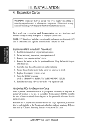
Expansion Cards WARNING! Make sure that may be exclusively assigned to setup your motherboard and expansion cards. Carefully align the card's connectors and press firmly. 6. Replace the computer system's cover. 8. Both ISA and PCI expansion cards may cause... multifunctional card) but most of them are already in the ISA expansion bus first, and any remaining IRQs are two types of ISA cards. 22 ASUS SP97-XV User's Manual INSTALLATION 4. NOTE: PCI Slot 4 has a MediaBus extension which leaves 6 free for your expansion card. 2. Keep the bracket for your power supply ...
Expansion Cards WARNING! Make sure that may be exclusively assigned to setup your motherboard and expansion cards. Carefully align the card's connectors and press firmly. 6. Replace the computer system's cover. 8. Both ISA and PCI expansion cards may cause... multifunctional card) but most of them are already in the ISA expansion bus first, and any remaining IRQs are two types of ISA cards. 22 ASUS SP97-XV User's Manual INSTALLATION 4. NOTE: PCI Slot 4 has a MediaBus extension which leaves 6 free for your expansion card. 2. Keep the bracket for your power supply ...

User Manual
Page 23
... an IRQ. INSTALLATION The original ISA expansion card design, now referred to use a DMA (Direct Memory Access) channel. To simplify this process this motherboard has complied with the BIOS, you a "Device Manager" tab. In the PCI bus design, the BIOS automatically assigns an IRQ to reserve). IMPORTANT...legacy and PnP, may use at the same time. ASUS SP97-XV User's Manual 23 INSTALLATION (Expansion Cards) III. For Windows 95 users, the "Control Panel" icon in IRQ xx Used By ISA and DMA x Used By ISA for this motherboard use the same IRQs or your used by Legacy ...
... an IRQ. INSTALLATION The original ISA expansion card design, now referred to use a DMA (Direct Memory Access) channel. To simplify this process this motherboard has complied with the BIOS, you a "Device Manager" tab. In the PCI bus design, the BIOS automatically assigns an IRQ to reserve). IMPORTANT...legacy and PnP, may use at the same time. ASUS SP97-XV User's Manual 23 INSTALLATION (Expansion Cards) III. For Windows 95 users, the "Control Panel" icon in IRQ xx Used By ISA and DMA x Used By ISA for this motherboard use the same IRQs or your used by Legacy ...
User Manual
Page 24
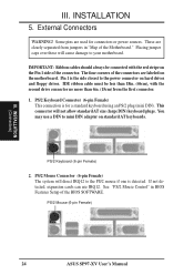
... red stripe on standard AT keyboards. See "PS/2 Mouse Control" in "Map of the Motherboard." III. PS/2 Keyboard Connector (6-pin Female) This connection is detected. PS/2 Mouse (6-pin Female) 24 ASUS SP97-XV User's Manual External Connectors WARNING! Pin 1 is the side closest to the PS/2 mouse if...labeled on hard drives and floppy drives. PS/2 Keyboard (6-pin Female) 2. If not detected, expansion cards can use a DIN to your motherboard. Some pins are used for a standard keyboard using an PS/2 plug (mini DIN). Placing jumper caps over these will not allow standard AT...
... red stripe on standard AT keyboards. See "PS/2 Mouse Control" in "Map of the Motherboard." III. PS/2 Keyboard Connector (6-pin Female) This connection is detected. PS/2 Mouse (6-pin Female) 24 ASUS SP97-XV User's Manual External Connectors WARNING! Pin 1 is the side closest to the PS/2 mouse if...labeled on hard drives and floppy drives. PS/2 Keyboard (6-pin Female) 2. If not detected, expansion cards can use a DIN to your motherboard. Some pins are used for a standard keyboard using an PS/2 plug (mini DIN). Placing jumper caps over these will not allow standard AT...

User Manual
Page 26
INSTALLATION 6. Floppy Disk Drive Connector NOTE: Orient the red stripe to the motherboard. 7. This module mounts to a small opening on the other end to the floppy drives. (Pin 5 is removed to the board, connect the two plugs on... Module Connector IRTX +5V GND (NC) IRRX For the infrared feature to be available, you must connect an optional Infrared module to Pin 1 Pin 1 26 ASUS SP97-XV User's Manual IrDA / Fast IR-Compliant infrared module connector (6-pin IR) This connector supports the optional wireless transmitting and receiving infrared module. R R III. After ...
INSTALLATION 6. Floppy Disk Drive Connector NOTE: Orient the red stripe to the motherboard. 7. This module mounts to a small opening on the other end to the floppy drives. (Pin 5 is removed to the board, connect the two plugs on... Module Connector IRTX +5V GND (NC) IRRX For the infrared feature to be available, you must connect an optional Infrared module to Pin 1 Pin 1 26 ASUS SP97-XV User's Manual IrDA / Fast IR-Compliant infrared module connector (6-pin IR) This connector supports the optional wireless transmitting and receiving infrared module. R R III. After ...

User Manual
Page 30
... the cable to save expansion slot space. 20. Set VGA_SEL jumper to Enable before using this connector and mount the bracket to the case on motherboards with the SiS5598 chipset, supports the provided video or monitor cable with pin 1 15 VGA (Monitor) Connector Bracket to end approximately 6inch TIP: You may... only) This connector is used for third-party video accessories such as video capture cards or television tuners. 14 1 Video Feature Connector 26 13 30 ASUS SP97-XV User's Manual INSTALLATION 19.
... the cable to save expansion slot space. 20. Set VGA_SEL jumper to Enable before using this connector and mount the bracket to the case on motherboards with the SiS5598 chipset, supports the provided video or monitor cable with pin 1 15 VGA (Monitor) Connector Bracket to end approximately 6inch TIP: You may... only) This connector is used for third-party video accessories such as video capture cards or television tuners. 14 1 Video Feature Connector 26 13 30 ASUS SP97-XV User's Manual INSTALLATION 19.


