User Manual
Page 4
... Connectors 24 Power Connection Procedures 31 IV. System Memory (SIMM & DIMM 17 SIMM Memory Installation 18 DIMM Memory Installation Procedures 19 3. BIOS SOFTWARE 32 Support Software 32 Flash Memory Writer Utility 32 Main Menu 32 Advanced Feature Menu 33 Managing and Updating Your Motherboard's BIOS 34 6. INSTALLATION 10 ASUS SP97-XV Motherboard Layout 10 Installation Steps 12 1. FEATURES 8 Features of the ASUS SP97-XV Motherboard 8 Parts of PNP and PCI Setup 46 Load BIOS Defaults 48 4 ASUS SP97-XV User's Manual BIOS Setup 35 Load Defaults 36 Standard CMOS Setup...
... Connectors 24 Power Connection Procedures 31 IV. System Memory (SIMM & DIMM 17 SIMM Memory Installation 18 DIMM Memory Installation Procedures 19 3. BIOS SOFTWARE 32 Support Software 32 Flash Memory Writer Utility 32 Main Menu 32 Advanced Feature Menu 33 Managing and Updating Your Motherboard's BIOS 34 6. INSTALLATION 10 ASUS SP97-XV Motherboard Layout 10 Installation Steps 12 1. FEATURES 8 Features of the ASUS SP97-XV Motherboard 8 Parts of PNP and PCI Setup 46 Load BIOS Defaults 48 4 ASUS SP97-XV User's Manual BIOS Setup 35 Load Defaults 36 Standard CMOS Setup...
User Manual
Page 5
.... SOFTWARE DRIVERS 68 Software Drivers 68 1. OS/2 V2.1 86 7. Double Bytes OS/2 Warp 88 ASUS SP97-XV User's Manual 5 SUPPORT SOFTWARE 52 Desktop Management Interface (DMI 52 Introducing the ASUS DMI Configuration Utility 52 System Requirements 52 Using the ASUS DMI Configuration Utility 53 Notes 53 VI. OS/2 V3.0 (Warp 87 8. SVGAUTL.EXE 61 IX. Autodesk ADI 4.2 -Protected Mode 80 6. DOS UTILITY 61 DOS Utility 61 1. CONTENTS Load Setup Defaults 48 Supervisor Password and User Password 49 IDE HDD Auto Detection...
.... SOFTWARE DRIVERS 68 Software Drivers 68 1. OS/2 V2.1 86 7. Double Bytes OS/2 Warp 88 ASUS SP97-XV User's Manual 5 SUPPORT SOFTWARE 52 Desktop Management Interface (DMI 52 Introducing the ASUS DMI Configuration Utility 52 System Requirements 52 Using the ASUS DMI Configuration Utility 53 Notes 53 VI. OS/2 V3.0 (Warp 87 8. SVGAUTL.EXE 61 IX. Autodesk ADI 4.2 -Protected Mode 80 6. DOS UTILITY 61 DOS Utility 61 1. CONTENTS Load Setup Defaults 48 Supervisor Password and User Password 49 IDE HDD Auto Detection...
User Manual
Page 7
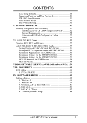
... drives (1) Floppy ribbon cable for (1) 5.25inch floppy and (2) 3.5inch floppies (1) bag of spare jumpers (1) diskette of support drivers and utilities: • Flash Memory Writer utility to update the onboard programmable BIOS • Desktop Management Interface (DMI) utility • Readme files for descriptions and use of the files • Technical Support Form (1) User's Manual (1) video ribbon cable with bracket for the onboard VGA version only external infrared (IrDA) module (optional) ASUS PCI-SC200 Fast-SCSI or PCI-SC860 Ultra-Fast SCSI card (optional) ASUS SP97-XV User's Manual...
... drives (1) Floppy ribbon cable for (1) 5.25inch floppy and (2) 3.5inch floppies (1) bag of spare jumpers (1) diskette of support drivers and utilities: • Flash Memory Writer utility to update the onboard programmable BIOS • Desktop Management Interface (DMI) utility • Readme files for descriptions and use of the files • Technical Support Form (1) User's Manual (1) video ribbon cable with bracket for the onboard VGA version only external infrared (IrDA) module (optional) ASUS PCI-SC200 Fast-SCSI or PCI-SC860 Ultra-Fast SCSI card (optional) ASUS SP97-XV User's Manual...

User Manual
Page 8
... be used at the same time, damage may occur. • Easy Installation: Incorporates BIOS that supports autodetection of hard disk drives, expansion cards, and other devices virtually automatic. • ISA and PCI Expansion Slots: Provides four 16-bit ISA slots and four 32-bit PCI slots • Super Multi-I/O: Provides two high-speed UART-compatible serial ports and one parallel port with onboard 512K Pipelined Burst SRAM. • IrDA Connector: Supports an optional infrared module for greater support. 8 ASUS SP97-XV User's Manual...
... be used at the same time, damage may occur. • Easy Installation: Incorporates BIOS that supports autodetection of hard disk drives, expansion cards, and other devices virtually automatic. • ISA and PCI Expansion Slots: Provides four 16-bit ISA slots and four 32-bit PCI slots • Super Multi-I/O: Provides two high-speed UART-compatible serial ports and one parallel port with onboard 512K Pipelined Burst SRAM. • IrDA Connector: Supports an optional infrared module for greater support. 8 ASUS SP97-XV User's Manual...

User Manual
Page 10
...-pin module) VGA Connector III. BF0 BF1 BF2 512KB Pipelined Burst L2 Cache SiS 5582 Chipset or SiS 5598 Chipset Floppy Drives Wake on LAN Multi I/O Chip PCI Slot 1 PCI Slot 2 PCI Slot 3 R PCI Slot 4 ISA Slot 1 ISA Slot 2 VGA Feature Conn. ISA Slot 3 Flash EEPROM (Programable BIOS) CHA_FAN CMOS Power CR2032 3 Volt Cell RTCLR IrDA IDE LED Secondary IDE Primary IDE ISA Slot 4 Panel Conn. NOTE: Outlined components are available only with the onboard VGA version. 10 ASUS SP97-XV User's Manual INSTALLATION (Motherboard Layout) CPU_FAN COM 2 Row 3 2 3 2 1 0 1 0 BUS Ratio...
...-pin module) VGA Connector III. BF0 BF1 BF2 512KB Pipelined Burst L2 Cache SiS 5582 Chipset or SiS 5598 Chipset Floppy Drives Wake on LAN Multi I/O Chip PCI Slot 1 PCI Slot 2 PCI Slot 3 R PCI Slot 4 ISA Slot 1 ISA Slot 2 VGA Feature Conn. ISA Slot 3 Flash EEPROM (Programable BIOS) CHA_FAN CMOS Power CR2032 3 Volt Cell RTCLR IrDA IDE LED Secondary IDE Primary IDE ISA Slot 4 Panel Conn. NOTE: Outlined components are available only with the onboard VGA version. 10 ASUS SP97-XV User's Manual INSTALLATION (Motherboard Layout) CPU_FAN COM 2 Row 3 2 3 2 1 0 1 0 BUS Ratio...
User Manual
Page 11
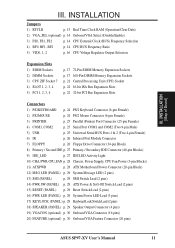
... Serial BUS Ports 1 & 2 (Two 4-pin Female) 6) IR p. 26 Infrared Port Module Connector 7) FLOPPY p. 26 Floppy Drive Connector (34-pin Block) 8) Primary / Second IDE p. 27 Primary / Secondary IDE Connector (40-pin Blocks) 9) IDE_LED p. 27 IDE LED Activity Light 10) CHA, PWR, CPU_FAN p. 28 Chassis, Power Supply, CPU Fan Power (3-pin Blocks) 11) ATXPWR p. 28 ATX Motherboard Power Connector (20-pin Block) 12) MSG LED (PANEL) p. 29 System Message LED (2 pins) 13) SMI (PANEL) p. 29 SMI Switch Lead (2 pins) 14) PWR SW (PANEL) p. 29 ATX Power & Soft-Off Switch Lead (2 pins) 15) RESET...
... Serial BUS Ports 1 & 2 (Two 4-pin Female) 6) IR p. 26 Infrared Port Module Connector 7) FLOPPY p. 26 Floppy Drive Connector (34-pin Block) 8) Primary / Second IDE p. 27 Primary / Secondary IDE Connector (40-pin Blocks) 9) IDE_LED p. 27 IDE LED Activity Light 10) CHA, PWR, CPU_FAN p. 28 Chassis, Power Supply, CPU Fan Power (3-pin Blocks) 11) ATXPWR p. 28 ATX Motherboard Power Connector (20-pin Block) 12) MSG LED (PANEL) p. 29 System Message LED (2 pins) 13) SMI (PANEL) p. 29 SMI Switch Lead (2 pins) 14) PWR SW (PANEL) p. 29 ATX Power & Soft-Off Switch Lead (2 pins) 15) RESET...

User Manual
Page 12
... ASUS SP97-XV User's Manual Hold components by the edges and try not to connect pins 2&3. Place components on a grounded antistatic pad or on the bag that both of jumpers. III. Set Jumpers on the board. Install Expansion Cards 5. Setup the BIOS Software 1. Pin 1 Pin 1 erboards is written besides pin 1 on the motherboard. WARNING! Unplug your hands to a safely grounded object or to connect jumper pins (JP) on jumpers with the keyboard connector away from other components. 4. Pin...
... ASUS SP97-XV User's Manual Hold components by the edges and try not to connect pins 2&3. Place components on a grounded antistatic pad or on the bag that both of jumpers. III. Set Jumpers on the board. Install Expansion Cards 5. Setup the BIOS Software 1. Pin 1 Pin 1 erboards is written besides pin 1 on the motherboard. WARNING! Unplug your hands to a safely grounded object or to connect jumper pins (JP) on jumpers with the keyboard connector away from other components. 4. Pin...

User Manual
Page 13
... should enter BIOS to "Load Setup Defaults" and re-enter any user information after removing and reapplying this jumper to "Clear Data," (3) Move the jumper back to re-enter user preferences. INSTALLATION Jumper Settings 1. INSTALLATION (Jumpers) ASUS SP97-XV User's Manual 13 III. You must unplug the power cord to ensure that there is powered by this jumper and attaching a current meter to the "Operation" pins. Real Time Clock (RTC) RAM (RTCLR) The CMOS RAM is no power to your power supply to your motherboard.
... should enter BIOS to "Load Setup Defaults" and re-enter any user information after removing and reapplying this jumper to "Clear Data," (3) Move the jumper back to re-enter user preferences. INSTALLATION Jumper Settings 1. INSTALLATION (Jumpers) ASUS SP97-XV User's Manual 13 III. You must unplug the power cord to ensure that there is powered by this jumper and attaching a current meter to the "Operation" pins. Real Time Clock (RTC) RAM (RTCLR) The CMOS RAM is no power to your power supply to your motherboard.

User Manual
Page 14
... motherboard BIOS will automatically Enable or Disable the onboard VGA based on or off if necessary. CPU to the CPU. You need to be set the frequency ratio between the onboard VGA and a separate installed VGA expansion card within the CPU. The BUS Clock times the BUS Ratio equals the CPU's Internal frequency (the advertised CPU speed). 4. VGA_SEL Enable Disable Setting [2-3] (default) [1-2] VGA_SEL VGA_SEL Enable (Default) Disable Onboard VGA Selection 3. INSTALLATION (Jumpers) III. INSTALLATION 2. These must be stable. 14 ASUS SP97-XV User's Manual These...
... motherboard BIOS will automatically Enable or Disable the onboard VGA based on or off if necessary. CPU to the CPU. You need to be set the frequency ratio between the onboard VGA and a separate installed VGA expansion card within the CPU. The BUS Clock times the BUS Ratio equals the CPU's Internal frequency (the advertised CPU speed). 4. VGA_SEL Enable Disable Setting [2-3] (default) [1-2] VGA_SEL VGA_SEL Enable (Default) Disable Onboard VGA Selection 3. INSTALLATION (Jumpers) III. INSTALLATION 2. These must be stable. 14 ASUS SP97-XV User's Manual These...
User Manual
Page 31
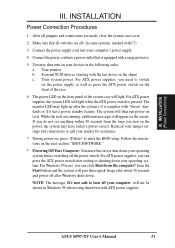
... system. INSTALLATION Power Connection Procedures 1. Connect the power cord into your devices in some systems, marked with ). 3. For ATX power supplies, you can press the ATX power switch after Windows shuts down with a surge protector. 5. ASUS SP97-XV User's Manual 31 Your system power. The power LED on the front of the system case will light when the ATX power switch is equipped with ATX power supplies. If you do not see anything within 30 seconds from the Start button and...
... system. INSTALLATION Power Connection Procedures 1. Connect the power cord into your devices in some systems, marked with ). 3. For ATX power supplies, you can press the ATX power switch after Windows shuts down with a surge protector. 5. ASUS SP97-XV User's Manual 31 Your system power. The power LED on the front of the system case will light when the ATX power switch is equipped with ATX power supplies. If you do not see anything within 30 seconds from the Start button and...

User Manual
Page 32
... the Flash EPROM IMPORTANT: Flash Type may also be programmed by the Flash Memory Writer. Save Current BIOS To File (Perform as soon as your screen during bootup. Save the motherboard's BIOS file to the system disk. 32 ASUS SP97-XV User's Manual Main Menu 1. NOTE: A binary BIOS file is not programmable or not supported with the support software. Update BIOS Main Block From File 3. See "Flash Memory Writer Utility" in this file to see the files included in case you to the programmable flash ROM chip...
... the Flash EPROM IMPORTANT: Flash Type may also be programmed by the Flash Memory Writer. Save Current BIOS To File (Perform as soon as your screen during bootup. Save the motherboard's BIOS file to the system disk. 32 ASUS SP97-XV User's Manual Main Menu 1. NOTE: A binary BIOS file is not programmable or not supported with the support software. Update BIOS Main Block From File 3. See "Flash Memory Writer Utility" in this file to see the files included in case you to the programmable flash ROM chip...

User Manual
Page 34
....BAT" and "CONFIG.SYS" files. 2. If the Flash Memory Writer utility was not able to successfully update a complete BIOS file, your new diskette and select option 1 "Save Current BIOS to enter BIOS setup. Turn off your system will need service. 7. Enter 2 "Update BIOS Main Block From File" from the Main Menu or option 2 "Update BIOS Including Boot Block and ESCD" from your system may set the other items from the Main Menu. BIOS (Flash Memory Writer) 34 ASUS SP97-XV User's Manual You must select "Setup Default" to effect...
....BAT" and "CONFIG.SYS" files. 2. If the Flash Memory Writer utility was not able to successfully update a complete BIOS file, your new diskette and select option 1 "Save Current BIOS to enter BIOS setup. Turn off your system will need service. 7. Enter 2 "Update BIOS Main Block From File" from the Main Menu or option 2 "Update BIOS Including Boot Block and ESCD" from your system may set the other items from the Main Menu. BIOS (Flash Memory Writer) 34 ASUS SP97-XV User's Manual You must select "Setup Default" to effect...

User Manual
Page 35
... enter new setup information. You can be updated when BIOS upgrades are installing the motherboard, reconfiguring your system or you receive a Run Setup message, you run Setup, the CMOS SETUP UTILITY main program screen will need to run the Setup utility, as described in detail in particular, the hard disk specifications. When you will appear with the following options: IV. BIOS Setup The motherboard supports two programmable Flash ROM chips: 5 volts and 12 volts. The BIOS ROM of these memory chips...
... enter new setup information. You can be updated when BIOS upgrades are installing the motherboard, reconfiguring your system or you receive a Run Setup message, you run Setup, the CMOS SETUP UTILITY main program screen will need to run the Setup utility, as described in detail in particular, the hard disk specifications. When you will appear with the following options: IV. BIOS Setup The motherboard supports two programmable Flash ROM chips: 5 volts and 12 volts. The BIOS ROM of these memory chips...
User Manual
Page 37
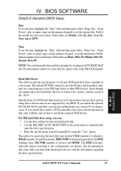
... drive specifications. IV. ASUS SP97-XV User's Manual 37 Follow the hour, minute and second format. Follow the month, day and year format. BIOS SOFTWARE Details of which is the "master" and the second is the "slave". NOTE: You can : • Use the Auto setting for all non-SCSI hard disk drives installed in the main menu to be entered here because they operate using the "User" option. the first of Standard CMOS Setup...
... drive specifications. IV. ASUS SP97-XV User's Manual 37 Follow the hour, minute and second format. Follow the month, day and year format. BIOS SOFTWARE Details of which is the "master" and the second is the "slave". NOTE: You can : • Use the Auto setting for all non-SCSI hard disk drives installed in the main menu to be entered here because they operate using the "User" option. the first of Standard CMOS Setup...

User Manual
Page 39
CPU Internal Cache (Enabled) Choose Disable to turn off the CPU's external level 2 cache. External Cache (Enabled) Choose Disable to turn off the CPU's built-in level 1 cache. This allows multiple operating systems to be the boot disk when set up the Power-On Self Test (POST) routine by the motherboard's design to reboot and investigate your preference. Some entries are noted in their default settings. ASUS SP97-XV User's Manual 39 IV. Details...
CPU Internal Cache (Enabled) Choose Disable to turn off the CPU's external level 2 cache. External Cache (Enabled) Choose Disable to turn off the CPU's built-in level 1 cache. This allows multiple operating systems to be the boot disk when set up the Power-On Self Test (POST) routine by the motherboard's design to reboot and investigate your preference. Some entries are noted in their default settings. ASUS SP97-XV User's Manual 39 IV. Details...

User Manual
Page 40
... expansion cards with installed DRAM of files from the computer system to be used for the User Password every time you will not function. F,A; IV. Boot Up Floppy Seek (Disabled) When enabled, the BIOS will reserve IRQ12 for an operating system. OS/2 Onboard Memory > 64M (Disabled) When using the Supervisor Password or User Password option from the floppy disk drive but not writes. IV. A,CDROM,C; D,A; IDE HDD Block Mode Sectors (HDD MAX) This field enhances hard disk performance by using OS...
... expansion cards with installed DRAM of files from the computer system to be used for the User Password every time you will not function. F,A; IV. Boot Up Floppy Seek (Disabled) When enabled, the BIOS will reserve IRQ12 for an operating system. OS/2 Onboard Memory > 64M (Disabled) When using the Supervisor Password or User Password option from the floppy disk drive but not writes. IV. A,CDROM,C; D,A; IDE HDD Block Mode Sectors (HDD MAX) This field enhances hard disk performance by using OS...

User Manual
Page 42
... cards that are known to the onboard floppy drive connector instead of a separate controller card. If you must decrease the speed to match your monitor displays unrecognizable information, you want to use the PCI Bus and some ISA cards that specifically require this to Disabled. 42 ASUS SP97-XV User's Manual NOTE: Some DRAMs are not PCI 2.1 compliant, set this setting. Video BIOS Cacheable (Leave on default setting of Enabled) This allows the video BIOS to allocate either 1MB, 2MB or 4MB memory...
... cards that are known to the onboard floppy drive connector instead of a separate controller card. If you must decrease the speed to match your monitor displays unrecognizable information, you want to use the PCI Bus and some ISA cards that specifically require this to Disabled. 42 ASUS SP97-XV User's Manual NOTE: Some DRAMs are not PCI 2.1 compliant, set this setting. Video BIOS Cacheable (Leave on default setting of Enabled) This allows the video BIOS to allocate either 1MB, 2MB or 4MB memory...

User Manual
Page 45
... controls the time-out settings. You may, however, configure your system to power up at a certain time and day by selecting By Date...IRQ3 (device)-IRQ15 (device) You can individually Enable or Disable each of the day by selecting Everyday, which will not display with Blank Screen selected). BIOS (Power Management) ASUS SP97-XV User's Manual 45 This feature does not affect SCSI hard disks. Blank Screen only blanks the screen (use...
... controls the time-out settings. You may, however, configure your system to power up at a certain time and day by selecting By Date...IRQ3 (device)-IRQ15 (device) You can individually Enable or Disable each of the day by selecting Everyday, which will not display with Blank Screen selected). BIOS (Power Management) ASUS SP97-XV User's Manual 45 This feature does not affect SCSI hard disks. Blank Screen only blanks the screen (use...

User Manual
Page 47
... available options; If you install a legacy ISA card that the displayed IRQ is not used or an ISA Configuration Utility (ICU) is being used to Disabled. the ISA MEM Block SIZE field will then appear for these devices are connected to Yes. SYMBIOS SCSI BIOS (Auto) The default uses Auto settings for each field is being used by a legacy ISA card. If you are not using that IRQ to the onboard USB connector, the resource settings or...
... available options; If you install a legacy ISA card that the displayed IRQ is not used or an ISA Configuration Utility (ICU) is being used to Disabled. the ISA MEM Block SIZE field will then appear for these devices are connected to Yes. SYMBIOS SCSI BIOS (Auto) The default uses Auto settings for each field is being used by a legacy ISA card. If you are not using that IRQ to the onboard USB connector, the resource settings or...

User Manual
Page 50
... OPTIONS field (2, 1, 3 in the Chipset Features Setup screen. The autodetection feature can only install two IDE hard disk drives. The onboard PCI IDE controller supports Enhanced IDE, with parameters for that does not feature Enhanced IDE support for an LBA drive. Some IDE drives can be detected, with two connectors for a particular IDE hard disk. If you want to enter zeros after that supports the LBA mode, three lines will appear listed beside the drive letter on it. 50 ASUS SP97-XV User's Manual...
... OPTIONS field (2, 1, 3 in the Chipset Features Setup screen. The autodetection feature can only install two IDE hard disk drives. The onboard PCI IDE controller supports Enhanced IDE, with parameters for that does not feature Enhanced IDE support for an LBA drive. Some IDE drives can be detected, with two connectors for a particular IDE hard disk. If you want to enter zeros after that supports the LBA mode, three lines will appear listed beside the drive letter on it. 50 ASUS SP97-XV User's Manual...


