PU-DLS User Manual
Page 11
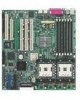
...PU-DLS specifications summary CPU Chipsets Front Side Bus (FSB) Memory Onboard LAN Onboard SCSI Expansion slots Rear panel I/O Internal connectors BIOS features Form Factor Support CD contents Support for dual Intel® Xeon™ processors with speeds up to 3.06 GHz On-die 512KB L2 cache Intel E7501 (Plumas 533) MCH Intel...and WOR connectors 4Mb Firmware Hub (FWH), Award BIOS with ACPI, DMI, Green, PnP features, and Enhanced Server BIOS features Extended ATX form factor: 12 in x 13 in (30.5 cm x 33 cm) Device drivers Utilities Contact information * Specifications are subject to change ...
...PU-DLS specifications summary CPU Chipsets Front Side Bus (FSB) Memory Onboard LAN Onboard SCSI Expansion slots Rear panel I/O Internal connectors BIOS features Form Factor Support CD contents Support for dual Intel® Xeon™ processors with speeds up to 3.06 GHz On-die 512KB L2 cache Intel E7501 (Plumas 533) MCH Intel...and WOR connectors 4Mb Firmware Hub (FWH), Award BIOS with ACPI, DMI, Green, PnP features, and Enhanced Server BIOS features Extended ATX form factor: 12 in x 13 in (30.5 cm x 33 cm) Device drivers Utilities Contact information * Specifications are subject to change ...

PU-DLS User Manual
Page 15
The PU-DLS incorporates dual Intel® Xeon™ processors in 604-pin package coupled with the list below. 1.2 Package contents Check your PU-DLS package for the following items. ASUS PU-DLS motherboard Extended ATX form factor: 12 in x 13 in (30.5 cm x 33 cm) ASUS PU-DLS support CD I/O shield 80-conductor ribbon cable for UltraDMA100/66/33 IDE drives Ribbon cable for...
The PU-DLS incorporates dual Intel® Xeon™ processors in 604-pin package coupled with the list below. 1.2 Package contents Check your PU-DLS package for the following items. ASUS PU-DLS motherboard Extended ATX form factor: 12 in x 13 in (30.5 cm x 33 cm) ASUS PU-DLS support CD I/O shield 80-conductor ribbon cable for UltraDMA100/66/33 IDE drives Ribbon cable for...
PU-DLS User Manual
Page 16
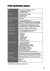
.../133MHz PCI-X bus onboard maximizes I /O and server management cards. 1.3 Special features 1.3.1 Product highlights Latest processor technology The PU-DLS motherboard supports the Intel® Xeon processor via dual 604-pin surface mount ZIF sockets. See page 2-4 for the next generation 64-bit PCI...a significant increase in performance. The processor features the Intel® NetBurst™ micro-architecture that support 133MHz bus. DDR memory support Employing the Double Data Rate (DDR) memory technology, the PU-DLS motherboard supports up to 12GB of system memory using PC2100/1600...
.../133MHz PCI-X bus onboard maximizes I /O and server management cards. 1.3 Special features 1.3.1 Product highlights Latest processor technology The PU-DLS motherboard supports the Intel® Xeon processor via dual 604-pin surface mount ZIF sockets. See page 2-4 for the next generation 64-bit PCI...a significant increase in performance. The processor features the Intel® NetBurst™ micro-architecture that support 133MHz bus. DDR memory support Employing the Double Data Rate (DDR) memory technology, the PU-DLS motherboard supports up to 12GB of system memory using PC2100/1600...

PU-DLS User Manual
Page 20
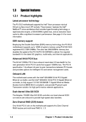
...connector 13. Floppy connector 17. Intel® 82540EM 32-bit PCI Gigabit Ethernet controller 21. Parallel port 24. RJ-45 port (for the specifications of the PU-DLS motherboard as pointed out in the picture ...ASUS ASIC 14. RJ-45 port (for detailed information on page 1-7. 1. 1.4 Motherboard overview Before you avoid mistakes that may damage the board and its physical configuration and available features to facilitate the motherboard installation and future upgrades. A sufficient knowledge of the motherboard specifications will also help you install the PU-DLS motherboard...
...connector 13. Floppy connector 17. Intel® 82540EM 32-bit PCI Gigabit Ethernet controller 21. Parallel port 24. RJ-45 port (for the specifications of the PU-DLS motherboard as pointed out in the picture ...ASUS ASIC 14. RJ-45 port (for detailed information on page 1-7. 1. 1.4 Motherboard overview Before you avoid mistakes that may damage the board and its physical configuration and available features to facilitate the motherboard installation and future upgrades. A sufficient knowledge of the motherboard specifications will also help you install the PU-DLS motherboard...
PU-DLS User Manual
Page 22
...) DRAM operating in lock-step, and provides Hub Interface 1.5 connection for ICH3-S and Hub Interface 2.0 connection for an SSI-type/ATX power supply. 2 DDR DIMM sockets. These sockets also support Intel Xeon CPUs with 512KB L2 cache and a 400/533 MHz system bus that provides high-performance I/O capability including 16-bit Hub...
...) DRAM operating in lock-step, and provides Hub Interface 1.5 connection for ICH3-S and Hub Interface 2.0 connection for an SSI-type/ATX power supply. 2 DDR DIMM sockets. These sockets also support Intel Xeon CPUs with 512KB L2 cache and a 400/533 MHz system bus that provides high-performance I/O capability including 16-bit Hub...

PU-DLS User Manual
Page 23
...& 4 IDE devices. This PCI-based VGA controller supports 8MB display SDRAM for the floppy disk drive. ASUS PU-DLS motherboard user guide 1-9 This chip performs multiple system functions that the CPUs installed on the motherboard, and serves as a reminder to turn off the system power before plugging or unplugging devices. 12 SCSI ...) and secondary (black) connectors are not identical. This LED lights up to prevent incorrect insertion of the floppy disk cable. 17 Intel® ICH3-S I /O functionality. This Low Pin Count (LPC) interface provides the commonly used Super I /O hub.
...& 4 IDE devices. This PCI-based VGA controller supports 8MB display SDRAM for the floppy disk drive. ASUS PU-DLS motherboard user guide 1-9 This chip performs multiple system functions that the CPUs installed on the motherboard, and serves as a reminder to turn off the system power before plugging or unplugging devices. 12 SCSI ...) and secondary (black) connectors are not identical. This LED lights up to prevent incorrect insertion of the floppy disk cable. 17 Intel® ICH3-S I /O functionality. This Low Pin Count (LPC) interface provides the commonly used Super I /O hub.
PU-DLS User Manual
Page 24
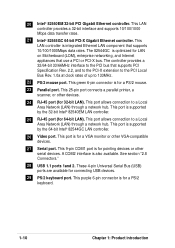
...is also available. This port is for a PS/2 keyboard. 1-10 Chapter 1: Product introduction This 9-pin COM1 port is supported by the 32-bit Intel® 82540EM LAN controller. 25 RJ-45 port (for a VGA monitor or other serial devices. See section "2.8 Connectors." 28 USB 1.1 ports 1and...-bit LAN). The 82544GC is supported by the 64-bit Intel® 82544GC LAN controller. 26 Video port. This port is optimized for a PS/2 mouse. 23 Parallel port. This green 6-pin connector is for LAN on Motherboard (LOM), enterprise networking, and Internet appliances that supports PCI ...
...is also available. This port is for a PS/2 keyboard. 1-10 Chapter 1: Product introduction This 9-pin COM1 port is supported by the 32-bit Intel® 82540EM LAN controller. 25 RJ-45 port (for a VGA monitor or other serial devices. See section "2.8 Connectors." 28 USB 1.1 ports 1and...-bit LAN). The 82544GC is supported by the 64-bit Intel® 82544GC LAN controller. 26 Video port. This port is optimized for a PS/2 mouse. 23 Parallel port. This green 6-pin connector is for LAN on Motherboard (LOM), enterprise networking, and Internet appliances that supports PCI ...
PU-DLS User Manual
Page 28
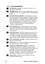
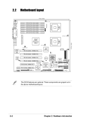
These components are optional. 30.5cm (12in) 2.2 Motherboard layout ® PU-DLS mPGA 604 Socket 1 (u50) J14 PS/2 T: Mouse B: Keyboard USB1 USB2 ... module) CPU_FAN1 PARALLEL PORT SSI/ATX POWER VGA RJ-45 (LAN-2) RJ-45 (LAN-1) Intel 82544GC PCI-X Gigabit LAN Intel 82540EM 32-bit Gigabit LAN J1 COM2 CHASSIS_FAN2 mPGA 604 Socket 2 (u49) Intel® E7501 (Plumas 533) ... J3 CR2032 3V Lithium Cell CMOS Power Adaptec AIC-7902W SCSI Controller Super I/O ASUS ASIC with Hardware Monitor J4 J6 WOR1 Intel I/O Controller Hub (ICH3-S) FLOPPY1 SCSI-B 34 68 CPULED1 4Mbit Firmware Hub J5...
These components are optional. 30.5cm (12in) 2.2 Motherboard layout ® PU-DLS mPGA 604 Socket 1 (u50) J14 PS/2 T: Mouse B: Keyboard USB1 USB2 ... module) CPU_FAN1 PARALLEL PORT SSI/ATX POWER VGA RJ-45 (LAN-2) RJ-45 (LAN-1) Intel 82544GC PCI-X Gigabit LAN Intel 82540EM 32-bit Gigabit LAN J1 COM2 CHASSIS_FAN2 mPGA 604 Socket 2 (u49) Intel® E7501 (Plumas 533) ... J3 CR2032 3V Lithium Cell CMOS Power Adaptec AIC-7902W SCSI Controller Super I/O ASUS ASIC with Hardware Monitor J4 J6 WOR1 Intel I/O Controller Hub (ICH3-S) FLOPPY1 SCSI-B 34 68 CPULED1 4Mbit Firmware Hub J5...

PU-DLS User Manual
Page 30
..., and data transfer rate of the CPU socket. The motherboard supports either one CPU, you are designed for the Intel Processor in socket 1. This mark indicates the processor Pin 1 that should match a specific corner of up to 4.2/3.2GB/s. ® PU-DLS Prestonia Gold Arrow PU-DLS Socket 604 Note in the illustration that features the hyper...
..., and data transfer rate of the CPU socket. The motherboard supports either one CPU, you are designed for the Intel Processor in socket 1. This mark indicates the processor Pin 1 that should match a specific corner of up to 4.2/3.2GB/s. ® PU-DLS Prestonia Gold Arrow PU-DLS Socket 604 Note in the illustration that features the hyper...

PU-DLS User Manual
Page 32
Follow these steps to ensure optimum thermal condition and performance. Place the heatsink and fan assembly on the corner of the installed CPU, making sure that it fits in place. 2. Hook one end of the retention bracket into the protruding tab on top of the plastic retention base. (The retention base comes installed with the motherboard.) 2-6 Chapter 2: Hardware information 2.4.3 Installing the CPU heatsink and fan The Intel® Xeon™ processors require specially designed heatsink and fan assembly to install the CPU heatsink and fan. 1.
Follow these steps to ensure optimum thermal condition and performance. Place the heatsink and fan assembly on the corner of the installed CPU, making sure that it fits in place. 2. Hook one end of the retention bracket into the protruding tab on top of the plastic retention base. (The retention base comes installed with the motherboard.) 2-6 Chapter 2: Hardware information 2.4.3 Installing the CPU heatsink and fan The Intel® Xeon™ processors require specially designed heatsink and fan assembly to install the CPU heatsink and fan. 1.

PU-DLS User Manual
Page 39
... PCI-X1 and PCI-X2) 133 MHz 100 MHz 66 MHz 133 MHz 100 MHz 66 MHz * PCI-X1 supports a ZCR (Zero Channel RAID) card. ASUS PU-DLS motherboard user guide 2-13 The PCI bus speed for servers to install PCI and PCI-X cards at the same time, but the bus speed will be... speed Channel A Intel 82544GC PCI-X LAN None One (on PCI-X3 or PCI-X4) Two (on PCI-X3 and PCI-X4) Channel B Adaptec AIC-7902W None PCI-X Ultra-320 SCSI One (on PCI-X1 or PCI-X2) Two (on the motherboard. 2.6.3 PCI slots This motherboard implements the PCI-X (Peripheral Component Interconnect Extended) bus technology...
... PCI-X1 and PCI-X2) 133 MHz 100 MHz 66 MHz 133 MHz 100 MHz 66 MHz * PCI-X1 supports a ZCR (Zero Channel RAID) card. ASUS PU-DLS motherboard user guide 2-13 The PCI bus speed for servers to install PCI and PCI-X cards at the same time, but the bus speed will be... speed Channel A Intel 82544GC PCI-X LAN None One (on PCI-X3 or PCI-X4) Two (on PCI-X3 and PCI-X4) Channel B Adaptec AIC-7902W None PCI-X Ultra-320 SCSI One (on PCI-X1 or PCI-X2) Two (on the motherboard. 2.6.3 PCI slots This motherboard implements the PCI-X (Peripheral Component Interconnect Extended) bus technology...
PU-DLS User Manual
Page 41
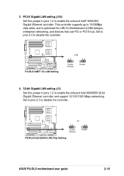
...to enable the onboard Intel 82540EM 32-bit Gigabit Ethernet controller and support 10/100/1000 Mbps networking. This controller supports up to disable the controller. ® PU-DLS J1 12 23 Enable (Default) Disable PU-DLS Intel 82540 LAN Chip Setting ASUS PU-DLS motherboard user guide 2-15... PCI-X Gigabit LAN setting (J15) Set this jumper to pins 1-2 to enable the onboard Intel® 82544GC Gigabit Ethernet controller. ...
...to enable the onboard Intel 82540EM 32-bit Gigabit Ethernet controller and support 10/100/1000 Mbps networking. This controller supports up to disable the controller. ® PU-DLS J1 12 23 Enable (Default) Disable PU-DLS Intel 82540 LAN Chip Setting ASUS PU-DLS motherboard user guide 2-15... PCI-X Gigabit LAN setting (J15) Set this jumper to pins 1-2 to enable the onboard Intel® 82544GC Gigabit Ethernet controller. ...
PU-DLS User Manual
Page 50
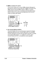
...(PCIX1) The 64-bit/100MHz PCI-X slot (colored green) supports the Adaptec Nighthawk2 ASR-2010S Zero-Channel RAID card or the Intel RAID Controller SRCZCR to connect SMBus (System Management Bus) devices. SMBus connector (6-1 pin J5) This connector allows you to provide ...and 0/5, cache memory modules with an SMBus host and/or other SMBus devices using the SMBus interface. ® PU-DLS 10. J5 1 PU-DLS SMBus Connector 11. SMBCLK Ground SMBDATA +3V ® PU-DLS PU-DLS Zero-Channel RAID 2-24 Chapter 2: Hardware information SMBus is a specific implementation of an I2C bus, a multi-...
...(PCIX1) The 64-bit/100MHz PCI-X slot (colored green) supports the Adaptec Nighthawk2 ASR-2010S Zero-Channel RAID card or the Intel RAID Controller SRCZCR to connect SMBus (System Management Bus) devices. SMBus connector (6-1 pin J5) This connector allows you to provide ...and 0/5, cache memory modules with an SMBus host and/or other SMBus devices using the SMBus interface. ® PU-DLS 10. J5 1 PU-DLS SMBus Connector 11. SMBCLK Ground SMBDATA +3V ® PU-DLS PU-DLS Zero-Channel RAID 2-24 Chapter 2: Hardware information SMBus is a specific implementation of an I2C bus, a multi-...

PU-DLS User Manual
Page 79
...] PCI Latency Timer [32] Leave on SCSI card can be used. Configuration options: [Disabled] [3 Controllers] ONB Intel 82544 LAN Boot ROM [Disabled] ONB Intel 82540 LAN Boot ROM [Disabled] When set to [Enabled], these fields allow the system to select the primary graphics card...BIOS will be enabled. If the SCSI controller is detected, the onboard SCSI BIOS will be disabled. Configuration options: [Disabled] [Enabled] ASUS PU-DLS motherboard user guide 4-21 Configuration options: [Auto] [Disabled] Primary VGA BIOS First [PCI VGA Card] This field allows you have a ...
...] PCI Latency Timer [32] Leave on SCSI card can be used. Configuration options: [Disabled] [3 Controllers] ONB Intel 82544 LAN Boot ROM [Disabled] ONB Intel 82540 LAN Boot ROM [Disabled] When set to [Enabled], these fields allow the system to select the primary graphics card...BIOS will be enabled. If the SCSI controller is detected, the onboard SCSI BIOS will be disabled. Configuration options: [Disabled] [Enabled] ASUS PU-DLS motherboard user guide 4-21 Configuration options: [Auto] [Disabled] Primary VGA BIOS First [PCI VGA Card] This field allows you have a ...

PU-DLS User Manual
Page 87
... keep the default setting [No]. Configuration options: [No] [Yes] Reset Configuration Data [No] The Extended System Configuration Data (ESCD) contain information about non-PnP devices. The system halts and displays a warning ...must set boot virus detection, ensuring a virus-free boot sector. If this motherboard, the following options are present onboard: [ Intel Corporation IBA 4.0.22 Slo (LAN A)] [ Intel Corporation IBA 4.0.22 Slo (LAN B)] 4th Boot : (Legacy) [Disabled] ...1st Boot sequence. Configuration options: [Disabled] [Enabled] ASUS PU-DLS motherboard user guide 4-29
... keep the default setting [No]. Configuration options: [No] [Yes] Reset Configuration Data [No] The Extended System Configuration Data (ESCD) contain information about non-PnP devices. The system halts and displays a warning ...must set boot virus detection, ensuring a virus-free boot sector. If this motherboard, the following options are present onboard: [ Intel Corporation IBA 4.0.22 Slo (LAN A)] [ Intel Corporation IBA 4.0.22 Slo (LAN B)] 4th Boot : (Legacy) [Disabled] ...1st Boot sequence. Configuration options: [Disabled] [Enabled] ASUS PU-DLS motherboard user guide 4-29
PU-DLS User Manual
Page 98
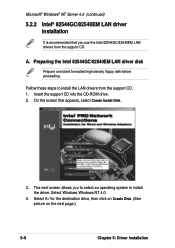
... page.) 5-6 Chapter 5: Driver installation Insert the support CD into the CD-ROM drive. 2. The next screen allows you use the Intel 82544GC/82540EM LAN drivers from the support CD. 1. Preparing the Intel 82544GC/82540EM LAN driver disk Prepare one blank formatted high density floppy disk before proceeding. Microsoft® Windows® NT...
... page.) 5-6 Chapter 5: Driver installation Insert the support CD into the CD-ROM drive. 2. The next screen allows you use the Intel 82544GC/82540EM LAN drivers from the support CD. 1. Preparing the Intel 82544GC/82540EM LAN driver disk Prepare one blank formatted high density floppy disk before proceeding. Microsoft® Windows® NT...

PU-DLS User Manual
Page 101
The following screen appears showing the Intel(R) PRO/1000 Family Adapter in the dialog box that you created, then click Have Disk... 5. When done, the following screen lists the Intel LAN adapters that appears, then click OK. Click Next and follow any other screen instructions to complete the installation. Type A:\ in the list. 8. Follow the succeeding screen instructions. 7. ASUS PU-DLS motherboard user guide 5-9 Insert the LAN driver disk that you can install. 6. Select Intel(R) PRO/1000 Family Adapter, then click OK. 4.
The following screen appears showing the Intel(R) PRO/1000 Family Adapter in the dialog box that you created, then click Have Disk... 5. When done, the following screen lists the Intel LAN adapters that appears, then click OK. Click Next and follow any other screen instructions to complete the installation. Type A:\ in the list. 8. Follow the succeeding screen instructions. 7. ASUS PU-DLS motherboard user guide 5-9 Insert the LAN driver disk that you can install. 6. Select Intel(R) PRO/1000 Family Adapter, then click OK. 4.
PU-DLS User Manual
Page 102
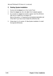
... Support CD. Microsoft® Windows® NT Server 4.0 (continued) C. Select the Adapter tab, then click Add. Double-click the Network icon in section "B. Preparing the Intel 82544GC/82540EM LAN Driver Disk" if you created from the list. Follow steps 4 to 8 in the Control Panel. 2.
... Support CD. Microsoft® Windows® NT Server 4.0 (continued) C. Select the Adapter tab, then click Add. Double-click the Network icon in section "B. Preparing the Intel 82544GC/82540EM LAN Driver Disk" if you created from the list. Follow steps 4 to 8 in the Control Panel. 2.

PU-DLS User Manual
Page 108
Select Windows 2000. 4. Preparing the Intel 82544GC/82540EM LAN driver disk Prepare one blank formatted high density floppy disk before proceeding. On the screen that you to select an operating system ... Disk. (See picture on the next page.) 5-16 Chapter 5: Driver installation Follow these steps to install the driver. A. The next screen allows you use the Intel 82544GC/82540EM LAN drivers from the support CD. 1. Insert the support CD into the CD-ROM drive. 2. Microsoft® Windows® 2000 Server (continued...
Select Windows 2000. 4. Preparing the Intel 82544GC/82540EM LAN driver disk Prepare one blank formatted high density floppy disk before proceeding. On the screen that you to select an operating system ... Disk. (See picture on the next page.) 5-16 Chapter 5: Driver installation Follow these steps to install the driver. A. The next screen allows you use the Intel 82544GC/82540EM LAN drivers from the support CD. 1. Insert the support CD into the CD-ROM drive. 2. Microsoft® Windows® 2000 Server (continued...

PU-DLS User Manual
Page 110
On the screen that appears, click on Intel PRO/1000 LAN Driver, then on an Existing System Installation You may update the LAN driver directly from the support CD. 1. When done, your Computer Management window shows the installed LAN adapters. 5-18 Chapter 5: Driver installation Follow the screen instructions to complete the driver update. Insert the support CD into the CD-ROM drive. Microsoft® Windows® 2000 Server (continued) B. Update Driver on the item Install Base Driver Only. 2.
On the screen that appears, click on Intel PRO/1000 LAN Driver, then on an Existing System Installation You may update the LAN driver directly from the support CD. 1. When done, your Computer Management window shows the installed LAN adapters. 5-18 Chapter 5: Driver installation Follow the screen instructions to complete the driver update. Insert the support CD into the CD-ROM drive. Microsoft® Windows® 2000 Server (continued) B. Update Driver on the item Install Base Driver Only. 2.


