
Motherboard Installation Guide
Page 17
ASUS P5W64 WS Professional 1-1 Before you for up to 7 devices I/O shield ASUS motherboard support CD InterVideo® Media Launcher User guide If any of ASUS quality motherboards! Thank you start installing the motherboard, and hardware devices on ...Cables Accessories Application CD Documentation ASUS P5W64 WS PRO motherboard 1 x 2-port IEEE 1394a module 1 x 2-port USB 2.0 module 1 x Floppy disk drive cable 1 x Ultra DMA 133/100/66 cable 7 x Serial ATA signal cables 4 x Serial ATA power cables for buying an ASUS® P5W64 WS Professional Workstation motherboard! 1.1 Welcome!
ASUS P5W64 WS Professional 1-1 Before you for up to 7 devices I/O shield ASUS motherboard support CD InterVideo® Media Launcher User guide If any of ASUS quality motherboards! Thank you start installing the motherboard, and hardware devices on ...Cables Accessories Application CD Documentation ASUS P5W64 WS PRO motherboard 1 x 2-port IEEE 1394a module 1 x 2-port USB 2.0 module 1 x Floppy disk drive cable 1 x Ultra DMA 133/100/66 cable 7 x Serial ATA signal cables 4 x Serial ATA power cables for buying an ASUS® P5W64 WS Professional Workstation motherboard! 1.1 Welcome!
Motherboard Installation Guide
Page 27
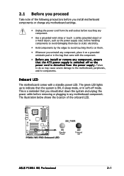
... it on a grounded antistatic pad or in the bag that came with a standby power LED. 2.1 Before you proceed Take note of the onboard LED. ® P5W64 WS PRO SB_PWR ON Standby Power P5W64 WS PRO Onboard LED OFF Powered Off ASUS P5W64 WS Professional 2-1 Failure to do so may cause severe damage to the motherboard, peripherals, and/or components.
... it on a grounded antistatic pad or in the bag that came with a standby power LED. 2.1 Before you proceed Take note of the onboard LED. ® P5W64 WS PRO SB_PWR ON Standby Power P5W64 WS PRO Onboard LED OFF Powered Off ASUS P5W64 WS Professional 2-1 Failure to do so may cause severe damage to the motherboard, peripherals, and/or components.
Motherboard Installation Guide
Page 28
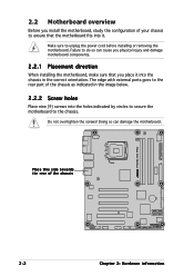
... it into the chassis in the image below. 2.2.2 Screw holes Place nine (9) screws into it. Make sure to the rear part of the chassis ® P5W64 WS PRO 2-2 Chapter 2: Hardware information Doing so can cause you physical injury and damage motherboard components. 2.2.1 Placement direction When installing the motherboard, make sure that you install...
... it into the chassis in the image below. 2.2.2 Screw holes Place nine (9) screws into it. Make sure to the rear part of the chassis ® P5W64 WS PRO 2-2 Chapter 2: Hardware information Doing so can cause you physical injury and damage motherboard components. 2.2.1 Placement direction When installing the motherboard, make sure that you install...
Motherboard Installation Guide
Page 30
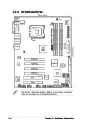
... SPDIF_O2 EATX12V LGA775 CPU_FAN PWR_FAN Super I/O ESATA PARALLEL PORT FLOPPY DDR2 DIMM_B1 (64 bit,240-pin module) DDR2 DIMM_B2 (64 bit,240-pin module) ® P5W64 WS PRO DDR2 DIMM_A1 (64 bit,240-pin module) DDR2 DIMM_A2 (64 bit,240-pin module) LAN1_USB12 LAN2_USB34 EATXPWR EZ_PLUG PRI_IDE AUDIO CHA_FAN1 Intel® 975X MCH...
... SPDIF_O2 EATX12V LGA775 CPU_FAN PWR_FAN Super I/O ESATA PARALLEL PORT FLOPPY DDR2 DIMM_B1 (64 bit,240-pin module) DDR2 DIMM_B2 (64 bit,240-pin module) ® P5W64 WS PRO DDR2 DIMM_A1 (64 bit,240-pin module) DDR2 DIMM_A2 (64 bit,240-pin module) LAN1_USB12 LAN2_USB34 EATXPWR EZ_PLUG PRI_IDE AUDIO CHA_FAN1 Intel® 975X MCH...

Motherboard Installation Guide
Page 34
... tab A Load lever PnP cap B This side of the arrow to a 135º angle. 2-8 Chapter 2: Hardware information Locate the CPU socket on the motherboard. ® P5W64 WS PRO P5W64 WS PRO CPU Socket 775 Before installing the CPU, make sure that the socket box is facing towards you and the load lever is on your thumb...
... tab A Load lever PnP cap B This side of the arrow to a 135º angle. 2-8 Chapter 2: Hardware information Locate the CPU socket on the motherboard. ® P5W64 WS PRO P5W64 WS PRO CPU Socket 775 Before installing the CPU, make sure that the socket box is facing towards you and the load lever is on your thumb...

Motherboard Installation Guide
Page 37
2. Hardware monitoring errors can occur if you fail to connect the CPU fan connector! ASUS P5W64 WS Professional 2-11 CPU_FAN ® P5W64 WS PRO CPU FAN PWM CPU FAN IN CPU FAN PWR GND P5W64 WS PRO CPU fan connector Do not forget to plug this connector. Connect the CPU fan cable to secure the heatsink and fan assembly in a diagonal sequence to the connector on the motherboard labeled CPU_FAN. Push down two fasteners at a time in place. A B A B A B B A 3.
2. Hardware monitoring errors can occur if you fail to connect the CPU fan connector! ASUS P5W64 WS Professional 2-11 CPU_FAN ® P5W64 WS PRO CPU FAN PWM CPU FAN IN CPU FAN PWR GND P5W64 WS PRO CPU fan connector Do not forget to plug this connector. Connect the CPU fan cable to secure the heatsink and fan assembly in a diagonal sequence to the connector on the motherboard labeled CPU_FAN. Push down two fasteners at a time in place. A B A B A B B A 3.
Motherboard Installation Guide
Page 40
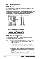
...physical dimensions as a DDR DIMM but has a 240-pin footprint compared to prevent installation on a DDR DIMM socket. Visit the ASUS website (www.asus.com) for the latest Qualified Vendors List. • Due to chipset resource allocation, the system may install 256 MB, 512 MB... memory modules. 2-14 Chapter 2: Hardware information The figure illustrates the location of the DDR2 DIMM sockets: ® P5W64 WS PRO DIMM_A1 DIMM_A2 DIMM_B1 DIMM_B2 P5W64 WS PRO 240-pin DDR2 DIMM sockets Channel Channel A Channel B Sockets DIMM_A1 and DIMM_A2 DIMM_B1 and DIMM_B2 2.4.2 Memory configurations You...
...physical dimensions as a DDR DIMM but has a 240-pin footprint compared to prevent installation on a DDR DIMM socket. Visit the ASUS website (www.asus.com) for the latest Qualified Vendors List. • Due to chipset resource allocation, the system may install 256 MB, 512 MB... memory modules. 2-14 Chapter 2: Hardware information The figure illustrates the location of the DDR2 DIMM sockets: ® P5W64 WS PRO DIMM_A1 DIMM_A2 DIMM_B1 DIMM_B2 P5W64 WS PRO 240-pin DDR2 DIMM sockets Channel Channel A Channel B Sockets DIMM_A1 and DIMM_A2 DIMM_B1 and DIMM_B2 2.4.2 Memory configurations You...
Motherboard Installation Guide
Page 49
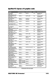
... Pro.(CHT) Pass ASUS EAX850PRO PCIEX16_1 WinXP Pro. Pass (BIOS: 7249.9.12.5.2AS05) PCIEX16_2 (CrossFire) ASUS EN5900 PCIEX16_1 WinXP Pro. AS01) PCIEX16_1 WinXP-64 Pro. Pass (BIOS: V5E4D.9.7.1.3. AS13) PCIEX16_1 PCIEX16_2 WinXP Pro.(JPN) Pass ASUS EAX700PRO Rev. Pass (BIOS: V5D4F.9.7. 1.4.AS02) ASUS EAX850XT....10.8198 ASUS P5W64 WS Professional 2-23 Qualified PCI Express x16 graphics cards Model Connect Interface ASUS EAX300 Rev: V1.00 (BIOS: V5b60.8.15.117.0) PCIEX16_1 ASUS EAX300SE-HM128 Rev: V1.00 (BIOS: V008.015.128.000) PCIEX16_1 ASUS EAX300SE-X Rev...
... Pro.(CHT) Pass ASUS EAX850PRO PCIEX16_1 WinXP Pro. Pass (BIOS: 7249.9.12.5.2AS05) PCIEX16_2 (CrossFire) ASUS EN5900 PCIEX16_1 WinXP Pro. AS01) PCIEX16_1 WinXP-64 Pro. Pass (BIOS: V5E4D.9.7.1.3. AS13) PCIEX16_1 PCIEX16_2 WinXP Pro.(JPN) Pass ASUS EAX700PRO Rev. Pass (BIOS: V5D4F.9.7. 1.4.AS02) ASUS EAX850XT....10.8198 ASUS P5W64 WS Professional 2-23 Qualified PCI Express x16 graphics cards Model Connect Interface ASUS EAX300 Rev: V1.00 (BIOS: V5b60.8.15.117.0) PCIEX16_1 ASUS EAX300SE-HM128 Rev: V1.00 (BIOS: V008.015.128.000) PCIEX16_1 ASUS EAX300SE-X Rev...
Motherboard Installation Guide
Page 53
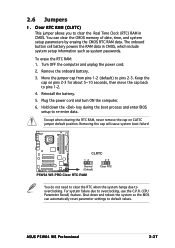
... key during the boot process and enter BIOS setup to pins 1-2. 4. ASUS P5W64 WS Professional 2-27 Turn OFF the computer and unplug the power cord. 2. Reinstall the battery. 5. Removing the cap will cause system boot failure! ® P5W64 WS PRO CLRTC 12 23 Normal (Default) P5W64 WS PRO Clear RTC RAM Clear RTC You do not need to clear the...
... key during the boot process and enter BIOS setup to pins 1-2. 4. ASUS P5W64 WS Professional 2-27 Turn OFF the computer and unplug the power cord. 2. Reinstall the battery. 5. Removing the cap will cause system boot failure! ® P5W64 WS PRO CLRTC 12 23 Normal (Default) P5W64 WS PRO Clear RTC RAM Clear RTC You do not need to clear the...

Motherboard Installation Guide
Page 57
... connector at the back of the following modes to configure your device. ® P5W64 WS PRO PRI_IDE NOTE: Orient the red markings (usually zigzag) on the IDE ribbon cable to PIN 1. P5W64 WS PRO IDE connector • Pin 20 on the IDE connector is removed to match the...the Ultra DMA (133/)100/66 signal cable. ASUS P5W64 WS Professional 2-31 Insert one of the floppy disk drive. There are three connectors on the floppy ribbon cable to prevent incorrect cable connection when using a FDD cable with a covered Pin 5. ® P5W64 WS PRO 2.7.2 Internal connectors 1 . FLOPPY NOTE: Orient...
... connector at the back of the following modes to configure your device. ® P5W64 WS PRO PRI_IDE NOTE: Orient the red markings (usually zigzag) on the IDE ribbon cable to PIN 1. P5W64 WS PRO IDE connector • Pin 20 on the IDE connector is removed to match the...the Ultra DMA (133/)100/66 signal cable. ASUS P5W64 WS Professional 2-31 Insert one of the floppy disk drive. There are three connectors on the floppy ribbon cable to prevent incorrect cable connection when using a FDD cable with a covered Pin 5. ® P5W64 WS PRO 2.7.2 Internal connectors 1 . FLOPPY NOTE: Orient...
Motherboard Installation Guide
Page 58
...Master Slave Cable connector Black Black Gray Black or gray If any device jumper is set . ® P5W64 WS PRO GND SATA_TXP2 SATA_TXN2 GND SATA_RXN2 SATA_RXP2 GND GND SATA_TXP3 SATA_TXN3 GND SATA_RXN3 SATA_RXP3 GND GND SATA_RXP0 SATA_RXN0 GND SATA_TXN0 SATA_TXP0 GND SATA4... P5W64 WS PRO SATA connectors SATA2 GND SATA_RXP1 SATA_RXN1 GND SATA_TXN1 SATA_TXP1 GND SATA3 SATA1 2-32 Chapter 2: Hardware information If you can create...
...Master Slave Cable connector Black Black Gray Black or gray If any device jumper is set . ® P5W64 WS PRO GND SATA_TXP2 SATA_TXN2 GND SATA_RXN2 SATA_RXP2 GND GND SATA_TXP3 SATA_TXN3 GND SATA_RXN3 SATA_RXP3 GND GND SATA_RXP0 SATA_RXN0 GND SATA_TXN0 SATA_TXP0 GND SATA4... P5W64 WS PRO SATA connectors SATA2 GND SATA_RXP1 SATA_RXN1 GND SATA_TXN1 SATA_TXP1 GND SATA3 SATA1 2-32 Chapter 2: Hardware information If you can create...
Motherboard Installation Guide
Page 59
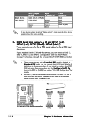
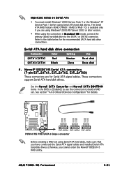
... using Serial ATA hard disks, make sure that you have connected the Serial ATA signal cables and installed Serial ATA hard disk drives; ASUS P5W64 WS Professional 2-33 Serial ATA hard disk drive connection Connector Color Setting Use SATA1/SATA2 Red Master Boot disk SATA3/SATA4 Black Slave Data disk 4...hard disk drive connections. See section "4.4.6 Onboard Devices Configuration" for details. ® P5W64 WS PRO GND RSATA_TX_0_DP RSATA_TX_0_DN GND RSATA_RX_0_DN RSATA_RX_0_DP GND GND RSATA_TX_1_DP RSATA_TX_1_DN GND RSATA_RX_1_DN RSATA_RX_1_DP GND GND RSATA_TX_2_DP RSATA_TX_2_DN...
... using Serial ATA hard disks, make sure that you have connected the Serial ATA signal cables and installed Serial ATA hard disk drives; ASUS P5W64 WS Professional 2-33 Serial ATA hard disk drive connection Connector Color Setting Use SATA1/SATA2 Red Master Boot disk SATA3/SATA4 Black Slave Data disk 4...hard disk drive connections. See section "4.4.6 Onboard Devices Configuration" for details. ® P5W64 WS PRO GND RSATA_TX_0_DP RSATA_TX_0_DN GND RSATA_RX_0_DN RSATA_RX_0_DP GND GND RSATA_TX_1_DP RSATA_TX_1_DN GND RSATA_RX_1_DN RSATA_RX_1_DP GND GND RSATA_TX_2_DP RSATA_TX_2_DN...
Motherboard Installation Guide
Page 60
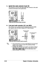
... default, this connector, set to the audio connector at the back of the optical drive. ® P5W64 WS PRO Right Audio Channel Ground Ground Left Audio Channel AGND PRESENCE# SENSE1_RETUR SENSE2_RETUR ® P5W64 WS PRO AGND NC NC NC CD (black) P5W64 WS PRO Internal audio connector 6 . 5 . MIC_L MIC_R Line out_R NC Line out_L PORT1 L PORT1 R PORT2 R SENSE_SEND PORT2...
... default, this connector, set to the audio connector at the back of the optical drive. ® P5W64 WS PRO Right Audio Channel Ground Ground Left Audio Channel AGND PRESENCE# SENSE1_RETUR SENSE2_RETUR ® P5W64 WS PRO AGND NC NC NC CD (black) P5W64 WS PRO Internal audio connector 6 . 5 . MIC_L MIC_R Line out_R NC Line out_L PORT1 L PORT1 R PORT2 R SENSE_SEND PORT2...
Motherboard Installation Guide
Page 61
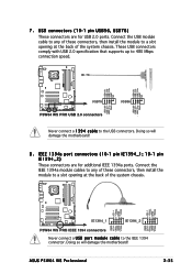
...ASUS P5W64 WS Professional 2-35 7 . Doing so will damage the motherboard! 8 . I E E E 1 3 9 4a port connectors (10-1 pin IE1394_1 ; 1 0 - 1 p i n IE1394_2) These connectors are for additional IEEE 1394a ports. Doing so will damage the motherboard! These USB connectors comply with USB 2.0 specification that supports up to 480 Mbps connection speed. ® P5W64 WS PRO... USB+5V USB_P6USB_P6+ GND NC USB+5V USB_P8USB_P8+ GND NC USB+5V USB_P5USB_P5+ GND USB78 P5W64 WS PRO USB 2.0 connectors USB+5V USB_P7USB_P7+ GND USB56 ...
...ASUS P5W64 WS Professional 2-35 7 . Doing so will damage the motherboard! 8 . I E E E 1 3 9 4a port connectors (10-1 pin IE1394_1 ; 1 0 - 1 p i n IE1394_2) These connectors are for additional IEEE 1394a ports. Doing so will damage the motherboard! These USB connectors comply with USB 2.0 specification that supports up to 480 Mbps connection speed. ® P5W64 WS PRO... USB+5V USB_P6USB_P6+ GND NC USB+5V USB_P8USB_P8+ GND NC USB+5V USB_P5USB_P5+ GND USB78 P5W64 WS PRO USB 2.0 connectors USB+5V USB_P7USB_P7+ GND USB56 ...

Motherboard Installation Guide
Page 62
... to use the chassis intrusion detection feature. By default, the pins labeled "Chassis Signal" and "Ground" are shorted with a jumper cap. CHASSIS (Default) P5W64 WS PRO Chassis intrusion connector ® P5W64 WS PRO +5VSB_MB Chassis Signal GND 2-36 Chapter 2: Hardware information The signal is removed or replaced. The chassis intrusion sensor or switch sends a high-level...
... to use the chassis intrusion detection feature. By default, the pins labeled "Chassis Signal" and "Ground" are shorted with a jumper cap. CHASSIS (Default) P5W64 WS PRO Chassis intrusion connector ® P5W64 WS PRO +5VSB_MB Chassis Signal GND 2-36 Chapter 2: Hardware information The signal is removed or replaced. The chassis intrusion sensor or switch sends a high-level...
Motherboard Installation Guide
Page 63
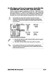
...damage the motherboard components. If you plug the rear chassis fan cable to the fan connectors. ASUS P5W64 WS Professional 2-37 PWR_FAN CPU_FAN CPU_FAN PWR_FAN Rotation +12V GND ® P5W64 WS PRO CPU FAN PWM CPU FAN IN CPU FAN PWR GND CHA_FAN1 CHA_FAN2 CHA_FAN1 Rotation +12V GND CHA_FAN2... GND +12V Rotation P5W64 WS PRO Fan connectors • Only the CPU_FAN, CHA_FAN1, and CHA_FAN2 connectors support the ASUS Q-Fan 2 feature. • CHA_FAN1 and CHA_FAN2 use the same Q-Fan 2 controller. Do ...
...damage the motherboard components. If you plug the rear chassis fan cable to the fan connectors. ASUS P5W64 WS Professional 2-37 PWR_FAN CPU_FAN CPU_FAN PWR_FAN Rotation +12V GND ® P5W64 WS PRO CPU FAN PWM CPU FAN IN CPU FAN PWR GND CHA_FAN1 CHA_FAN2 CHA_FAN1 Rotation +12V GND CHA_FAN2... GND +12V Rotation P5W64 WS PRO Fan connectors • Only the CPU_FAN, CHA_FAN1, and CHA_FAN2 connectors support the ASUS Q-Fan 2 feature. • CHA_FAN1 and CHA_FAN2 use the same Q-Fan 2 controller. Do ...

Motherboard Installation Guide
Page 64
... (24-pin EATXPWR, 2 x 4- p i n E ATX12V, 4 - Find the proper orientation and push down firmly until the connectors completely fit. ® P5W64 WS PRO EATX12V EZ_PLUG +12V GND EZ_DET +5V P5W64 WS PRO ATX power connectors GND GND GND GND +12V DC +12V DC +12V DC +12V DC EATXPWR +3 Volts +12 Volts +12 Volts +5V Standby Power...these connectors in only one orientation. Serial port connector (10-1 pin COM1) This connector is for ATX power supply plugs. COM1 PIN 1 ® P5W64 WS PRO P5W64 WS PRO COM port connector 1 2 . The power supply plugs are for a serial (COM) port.
... (24-pin EATXPWR, 2 x 4- p i n E ATX12V, 4 - Find the proper orientation and push down firmly until the connectors completely fit. ® P5W64 WS PRO EATX12V EZ_PLUG +12V GND EZ_DET +5V P5W64 WS PRO ATX power connectors GND GND GND GND +12V DC +12V DC +12V DC +12V DC EATXPWR +3 Volts +12 Volts +12 Volts +5V Standby Power...these connectors in only one orientation. Serial port connector (10-1 pin COM1) This connector is for ATX power supply plugs. COM1 PIN 1 ® P5W64 WS PRO P5W64 WS PRO COM port connector 1 2 . The power supply plugs are for a serial (COM) port.
Motherboard Installation Guide
Page 66
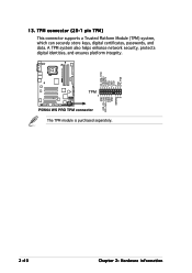
GND smb_clk_main smb_data_main LAD2 LAD1 GND SERIRQ X X 2-40 Chapter 2: Hardware information TPM connector (20-1 pin TPM) This connector supports a Trusted Platform Module (TPM) system, which can securely store keys, digital certificates, passwords, and data. CK_33M_TPM LFRAMEn LRESETn LAD3 +3.3V LAD0 +3.3V X GND LPC_PD# ® P5W64 WS PRO 13. TPM 1 P5W64 WS PRO TPM connector The TPM module is purchased separately. A TPM system also helps enhance network security, protects digital identities, and ensures platform integrity.
GND smb_clk_main smb_data_main LAD2 LAD1 GND SERIRQ X X 2-40 Chapter 2: Hardware information TPM connector (20-1 pin TPM) This connector supports a Trusted Platform Module (TPM) system, which can securely store keys, digital certificates, passwords, and data. CK_33M_TPM LFRAMEn LRESETn LAD3 +3.3V LAD0 +3.3V X GND LPC_PD# ® P5W64 WS PRO 13. TPM 1 P5W64 WS PRO TPM connector The TPM module is purchased separately. A TPM system also helps enhance network security, protects digital identities, and ensures platform integrity.

Motherboard Installation Guide
Page 67
...Requires an ATX power supply. Connect the chassis power LED cable to this connector. The speaker allows you turn on the BIOS settings. P5W64 WS PRO System panel connector • System power LED This 3-pin connector is for the HDD Activity LED. The system power LED lights up ... connector is in sleep or soft-off the system power. Connect the HDD Activity LED cable to this connector. ASUS P5W64 WS Professional 2-41 PLED+ PLED+5V Ground Ground Speaker ® P5W64 WS PRO IDE_LED+ IDE_LED- The IDE LED lights up when you to the HDD. • System warning speaker This 4-...
...Requires an ATX power supply. Connect the chassis power LED cable to this connector. The speaker allows you turn on the BIOS settings. P5W64 WS PRO System panel connector • System power LED This 3-pin connector is for the HDD Activity LED. The system power LED lights up ... connector is in sleep or soft-off the system power. Connect the HDD Activity LED cable to this connector. ASUS P5W64 WS Professional 2-41 PLED+ PLED+5V Ground Ground Speaker ® P5W64 WS PRO IDE_LED+ IDE_LED- The IDE LED lights up when you to the HDD. • System warning speaker This 4-...
Motherboard Installation Guide
Page 79
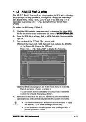
... or reset the system while updating the BIOS to a floppy disk or a USB flash disk, then restart the system. 3. ASUS P5W64 WS Professional 4-5 4.1.3 ASUS EZ Flash 2 utility The ASUS EZ Flash 2 feature allows you to update the BIOS without having to enable it is accessible by pressing + during POST to ... a floppy disk and using EZ Flash 2: 1. ASUSTek EZ Flash 2 BIOS ROM Utility V3.00 FLASH TYPE: Winbond W39V080A 8Mb LPC Current ROM BOARD: P5W64-WS Pro VER: 0204 DATE: 07/04/2006 Update ROM BOARD: Unknown VER: Unknown DATE: Unknown PATH: A:\ A: Note [Enter] Select [Tab] Switch [S] ...
... or reset the system while updating the BIOS to a floppy disk or a USB flash disk, then restart the system. 3. ASUS P5W64 WS Professional 4-5 4.1.3 ASUS EZ Flash 2 utility The ASUS EZ Flash 2 feature allows you to update the BIOS without having to enable it is accessible by pressing + during POST to ... a floppy disk and using EZ Flash 2: 1. ASUSTek EZ Flash 2 BIOS ROM Utility V3.00 FLASH TYPE: Winbond W39V080A 8Mb LPC Current ROM BOARD: P5W64-WS Pro VER: 0204 DATE: 07/04/2006 Update ROM BOARD: Unknown VER: Unknown DATE: Unknown PATH: A:\ A: Note [Enter] Select [Tab] Switch [S] ...


