
Motherboard Installation Guide
Page 17
... USB 2.0 module 1 x Floppy disk drive cable 1 x Ultra DMA 133/100/66 cable 7 x Serial ATA signal cables 4 x Serial ATA power cables for buying an ASUS® P5W64 WS Professional Workstation motherboard! ASUS P5W64 WS Professional 1-1 The motherboard delivers a host of new features and latest technologies, making it , check the items in the long line of the above items is...
... USB 2.0 module 1 x Floppy disk drive cable 1 x Ultra DMA 133/100/66 cable 7 x Serial ATA signal cables 4 x Serial ATA power cables for buying an ASUS® P5W64 WS Professional Workstation motherboard! ASUS P5W64 WS Professional 1-1 The motherboard delivers a host of new features and latest technologies, making it , check the items in the long line of the above items is...
Motherboard Installation Guide
Page 19
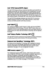
... The motherboard supports Intel® Pentium® 4 CPUs with peak bandwidths of up to run on the CPU loading and system speed or power requirement. ASUS P5W64 WS Professional 1-3 The Intel® 975X Express is the latest chipset designed to meet the higher bandwidth requirements of 800/667/533 MHz to support Dual PCI...
... The motherboard supports Intel® Pentium® 4 CPUs with peak bandwidths of up to run on the CPU loading and system speed or power requirement. ASUS P5W64 WS Professional 1-3 The Intel® 975X Express is the latest chipset designed to meet the higher bandwidth requirements of 800/667/533 MHz to support Dual PCI...
Motherboard Installation Guide
Page 21
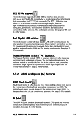
... motherboard uses a special design on to provide the total solution for your wired or wireless Internet, LAN, and file sharing requirements. ASUS P5W64 WS Professional 1-5 Trusted Platform Module (TPM) [optional] The Trusted Platform Module (TPM) is a fan-less and zero-noise cooling solution that... convenient single sign-on the printed circuit board (PCB) to provide faster data bandwidth for details. 1.3.2 ASUS Intelligence (AI) features ASUS Stack Cool 2 ASUS Stack Cool 2 is a secure microcontroller hardware component with dual Gigabit LAN controllers to systems and enable digital...
... motherboard uses a special design on to provide the total solution for your wired or wireless Internet, LAN, and file sharing requirements. ASUS P5W64 WS Professional 1-5 Trusted Platform Module (TPM) [optional] The Trusted Platform Module (TPM) is a fan-less and zero-noise cooling solution that... convenient single sign-on the printed circuit board (PCB) to provide faster data bandwidth for details. 1.3.2 ASUS Intelligence (AI) features ASUS Stack Cool 2 ASUS Stack Cool 2 is a secure microcontroller hardware component with dual Gigabit LAN controllers to systems and enable digital...
Motherboard Installation Guide
Page 23
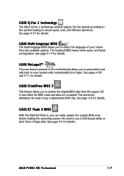
...the system BIOS even before loading the operating system. ASUS MyLogo2™ This new feature present in case when the BIOS codes and data are corrupted. See page 4-9 for details. ASUS P5W64 WS Professional 1-7 ASUS Multi-language BIOS The multi-language BIOS allows you ...to personalize and add style to ensure quiet, cool, and efficient operation. ASUS Q-Fan 2 technology The ASUS Q-Fan 2 technology smartly adjusts the fan speeds ...
...the system BIOS even before loading the operating system. ASUS MyLogo2™ This new feature present in case when the BIOS codes and data are corrupted. See page 4-9 for details. ASUS P5W64 WS Professional 1-7 ASUS Multi-language BIOS The multi-language BIOS allows you ...to personalize and add style to ensure quiet, cool, and efficient operation. ASUS Q-Fan 2 technology The ASUS Q-Fan 2 technology smartly adjusts the fan speeds ...
Motherboard Installation Guide
Page 26
Chapter summary 2 2.1 Before you proceed 2-1 2.2 Motherboard overview 2-2 2.3 Central Processing Unit (CPU 2-7 2.4 System memory 2-14 2.5 Expansion slots 2-20 2.6 Jumpers 2-27 2.7 Connectors 2-28 ASUS P5W64 WS Professional
Chapter summary 2 2.1 Before you proceed 2-1 2.2 Motherboard overview 2-2 2.3 Central Processing Unit (CPU 2-7 2.4 System memory 2-14 2.5 Expansion slots 2-20 2.6 Jumpers 2-27 2.7 Connectors 2-28 ASUS P5W64 WS Professional
Motherboard Installation Guide
Page 27
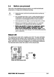
... any component, ensure that the ATX power supply is switched off mode. 2.1 Before you proceed Take note of the onboard LED. ® P5W64 WS PRO SB_PWR ON Standby Power P5W64 WS PRO Onboard LED OFF Powered Off ASUS P5W64 WS Professional 2-1 Onboard LED The motherboard comes with the component. • Before you install or remove any motherboard component.
... any component, ensure that the ATX power supply is switched off mode. 2.1 Before you proceed Take note of the onboard LED. ® P5W64 WS PRO SB_PWR ON Standby Power P5W64 WS PRO Onboard LED OFF Powered Off ASUS P5W64 WS Professional 2-1 Onboard LED The motherboard comes with the component. • Before you install or remove any motherboard component.
Motherboard Installation Guide
Page 29
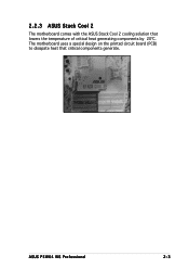
ASUS P5W64 WS Professional 2-3 2.2.3 ASUS Stack Cool 2 The motherboard comes with the ASUS Stack Cool 2 cooling solution that critical components generate. The motherboard uses a special design on the printed circuit board (PCB) to dissipate heat that lowers the temperature of critical heat generating components by 20ºC.
ASUS P5W64 WS Professional 2-3 2.2.3 ASUS Stack Cool 2 The motherboard comes with the ASUS Stack Cool 2 cooling solution that critical components generate. The motherboard uses a special design on the printed circuit board (PCB) to dissipate heat that lowers the temperature of critical heat generating components by 20ºC.
Motherboard Installation Guide
Page 33
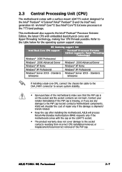
...ASUS P5W64 WS Professional 2-7 Contact your retailer immediately if the PnP cap is shipment/ transit-related. • Keep the cap after installing the motherboard. Standard, Windows® Server 2003 - OS licensing support list Intel Dual-Core CPU support P e n t i u m® P r o c e s s o r E x t r e m e Edition (supports Hyper-Threading T e c h n o l o g y) Windows® 2000 Professional...Home Windows® XP Home Windows® XP Professional Windows® XP Professional Windows® Server 2003 - ASUS will process Return Merchandise Authorization (RMA) requests ...
...ASUS P5W64 WS Professional 2-7 Contact your retailer immediately if the PnP cap is shipment/ transit-related. • Keep the cap after installing the motherboard. Standard, Windows® Server 2003 - OS licensing support list Intel Dual-Core CPU support P e n t i u m® P r o c e s s o r E x t r e m e Edition (supports Hyper-Threading T e c h n o l o g y) Windows® 2000 Professional...Home Windows® XP Home Windows® XP Professional Windows® XP Professional Windows® Server 2003 - ASUS will process Return Merchandise Authorization (RMA) requests ...

Motherboard Installation Guide
Page 35
... load plate (A), then A push the load lever (B) until it snaps into the CPU notch. Gold triangle mark The CPU fits in only one correct orientation. 4. ASUS P5W64 WS Professional 2-9 DO NOT force the CPU into the socket to ensure system stability. The motherboard supports Intel® Pentium® 4 LGA775 processors with your thumb and...
... load plate (A), then A push the load lever (B) until it snaps into the CPU notch. Gold triangle mark The CPU fits in only one correct orientation. 4. ASUS P5W64 WS Professional 2-9 DO NOT force the CPU into the socket to ensure system stability. The motherboard supports Intel® Pentium® 4 LGA775 processors with your thumb and...

Motherboard Installation Guide
Page 37
CPU_FAN ® P5W64 WS PRO CPU FAN PWM CPU FAN IN CPU FAN PWR GND P5W64 WS PRO CPU fan connector Do not forget to plug this connector. ASUS P5W64 WS Professional 2-11 A B A B A B B A 3. Hardware monitoring errors can occur if you fail to connect the CPU fan connector! Connect the CPU fan cable to secure the heatsink and fan assembly in place. Push down two fasteners at a time in a diagonal sequence to the connector on the motherboard labeled CPU_FAN. 2.
CPU_FAN ® P5W64 WS PRO CPU FAN PWM CPU FAN IN CPU FAN PWR GND P5W64 WS PRO CPU fan connector Do not forget to plug this connector. ASUS P5W64 WS Professional 2-11 A B A B A B B A 3. Hardware monitoring errors can occur if you fail to connect the CPU fan connector! Connect the CPU fan cable to secure the heatsink and fan assembly in place. Push down two fasteners at a time in a diagonal sequence to the connector on the motherboard labeled CPU_FAN. 2.
Motherboard Installation Guide
Page 39
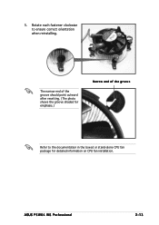
Rotate each fastener clockwise to the documentation in the boxed or stand-alone CPU fan package for detailed information on CPU fan installation. The narrow end of the groove should point outward after resetting. (The photo shows the groove shaded for emphasis.) Narrow end of the groove Refer to ensure correct orientation when reinstalling. 5. ASUS P5W64 WS Professional 2-13
Rotate each fastener clockwise to the documentation in the boxed or stand-alone CPU fan package for detailed information on CPU fan installation. The narrow end of the groove should point outward after resetting. (The photo shows the groove shaded for emphasis.) Narrow end of the groove Refer to ensure correct orientation when reinstalling. 5. ASUS P5W64 WS Professional 2-13
Motherboard Installation Guide
Page 41
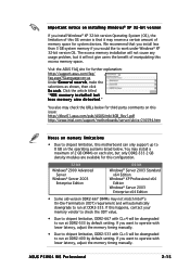
...® 2000 Advanced Server Windows® Server 2003 Enterprise Edition 64-bit Windows® Server 2003 Standard x64 Edition Windows® XP Professional x64 Edition Windows® Server 2003 Enterprise x64 Edition • Some old-version DDR2-667 DIMMs may not match Intel®'s On-... downgraded to operate with CL=3 will automatically downgrade to run at DDR2-533 by default setting. If you would like to run at DDR2-533. ASUS P5W64 WS Professional 2-15 You also may check the URLs below . b i t v e r s i o n If you install Windows® XP 32-bit version Operating System (...
...® 2000 Advanced Server Windows® Server 2003 Enterprise Edition 64-bit Windows® Server 2003 Standard x64 Edition Windows® XP Professional x64 Edition Windows® Server 2003 Enterprise x64 Edition • Some old-version DDR2-667 DIMMs may not match Intel®'s On-... downgraded to operate with CL=3 will automatically downgrade to run at DDR2-533 by default setting. If you would like to run at DDR2-533. ASUS P5W64 WS Professional 2-15 You also may check the URLs below . b i t v e r s i o n If you install Windows® XP 32-bit version Operating System (...
Motherboard Installation Guide
Page 43
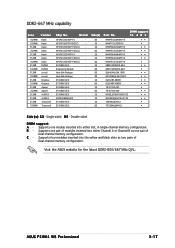
...BL12864AL664.16FA SS KLCC28F-A8EB5 DS KLCD48F-A8EB5 SS 78.91092.420 DS 78.01092.420 SS M20EL5G3H3160B1C0Z SS M20AD5Q3H3163J1C52 SS TS64MLQ64V6J DS TS128MLQ64V6J S i d e ( s ): S S - ASUS P5W64 WS Professional 2-17 DDR2-667 MHz capability Size Vendor 1024MB 1024MB 512MB 1024MB 512MB 512MB 1024MB 512MB 1024MB 512MB 1024MB 512MB 1024MB 512MB 1024MB 512MB 512MB 512MB...module inserted into the yellow and black slots as two pairs of modules inserted into either slot, in Single-channel memory configuration. Visit the ASUS website for the latest DDR2-800/667 MHz QVL.
...BL12864AL664.16FA SS KLCC28F-A8EB5 DS KLCD48F-A8EB5 SS 78.91092.420 DS 78.01092.420 SS M20EL5G3H3160B1C0Z SS M20AD5Q3H3163J1C52 SS TS64MLQ64V6J DS TS128MLQ64V6J S i d e ( s ): S S - ASUS P5W64 WS Professional 2-17 DDR2-667 MHz capability Size Vendor 1024MB 1024MB 512MB 1024MB 512MB 512MB 1024MB 512MB 1024MB 512MB 1024MB 512MB 1024MB 512MB 1024MB 512MB 512MB 512MB...module inserted into the yellow and black slots as two pairs of modules inserted into either slot, in Single-channel memory configuration. Visit the ASUS website for the latest DDR2-800/667 MHz QVL.
Motherboard Installation Guide
Page 45
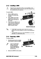
... lightly with extra force. 2. To install a DIMM: 1. Unlock a DIMM socket by pressing the retaining clips outward. 2. Remove the DIMM from the socket. 2 1 DDR2 DIMM notch ASUS P5W64 WS Professional 2-19 Align a DIMM on the socket such that it flips out with your fingers when pressing the retaining clips. Failure to do not support DDR...
... lightly with extra force. 2. To install a DIMM: 1. Unlock a DIMM socket by pressing the retaining clips outward. 2. Remove the DIMM from the socket. 2 1 DDR2 DIMM notch ASUS P5W64 WS Professional 2-19 Align a DIMM on the socket such that it flips out with your fingers when pressing the retaining clips. Failure to do not support DDR...
Motherboard Installation Guide
Page 47
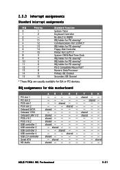
shared - - - - - - - - shared - - - - shared - - --- shared shared shared - shared - IRQ assignments for ISA or PCI devices. shared - - - shared - - - - - - - - shared - - - - - - - - shared shared ASUS P5W64 WS Professional 2-21 shared - - - - - - - - shared - - shared - - - - - shared - - shared - - - - shared - - - - 2.5.3 Interrupt assignments Standard interrupt assignments IRQ Priority 0 1 1 2 2 - 3 11 4 12 5 13 6 14 7 15 8 3 9 4 10 5 11 6 12 7 13 8 14 9 15 ...
shared - - - - - - - - shared - - - - shared - - --- shared shared shared - shared - IRQ assignments for ISA or PCI devices. shared - - - shared - - - - - - - - shared - - - - - - - - shared shared ASUS P5W64 WS Professional 2-21 shared - - - - - - - - shared - - shared - - - - - shared - - shared - - - - shared - - - - 2.5.3 Interrupt assignments Standard interrupt assignments IRQ Priority 0 1 1 2 2 - 3 11 4 12 5 13 6 14 7 15 8 3 9 4 10 5 11 6 12 7 13 8 14 9 15 ...
Motherboard Installation Guide
Page 49
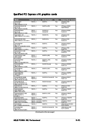
... ATI Radeon X1900XTX V8.241.0.0 ATI Radeon X1900CF V8.241.0.0 nVIDIA GeForce PCX5900 V6.14.10.8198 nVIDIA GeForce 6200 V6.14.10.8198 ASUS P5W64 WS Professional 2-23 Status Pass Pass Pass Pass Chipset/Driver Version ATI Radeon X300 V8.231.0.0 ATI Radeon X300SE (Hyper Memory) ATI Radeon X300SE V8....252.0.0 ATI Radeon X550 V8.241.0.0 ASUS EAX550GE 256M (BIOS: V5B60.8.15.139. AS13) PCIEX16_1 PCIEX16_2 WinXP Pro.(JPN) Pass ASUS EAX700PRO Rev. PN: 109-A47401-10 (BIOS: V009.007.001.004) PCIEX16_1 PCIEX16_2 Win2003-64 Standard ...
... ATI Radeon X1900XTX V8.241.0.0 ATI Radeon X1900CF V8.241.0.0 nVIDIA GeForce PCX5900 V6.14.10.8198 nVIDIA GeForce 6200 V6.14.10.8198 ASUS P5W64 WS Professional 2-23 Status Pass Pass Pass Pass Chipset/Driver Version ATI Radeon X300 V8.231.0.0 ATI Radeon X300SE (Hyper Memory) ATI Radeon X300SE V8....252.0.0 ATI Radeon X550 V8.241.0.0 ASUS EAX550GE 256M (BIOS: V5B60.8.15.139. AS13) PCIEX16_1 PCIEX16_2 WinXP Pro.(JPN) Pass ASUS EAX700PRO Rev. PN: 109-A47401-10 (BIOS: V009.007.001.004) PCIEX16_1 PCIEX16_2 Win2003-64 Standard ...
Motherboard Installation Guide
Page 53
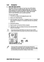
... the battery. 5. Removing the cap will cause system boot failure! ® P5W64 WS PRO CLRTC 12 23 Normal (Default) P5W64 WS PRO Clear RTC RAM Clear RTC You do not need to clear the RTC when the system hangs due to pins 2-3. ASUS P5W64 WS Professional 2-27 The onboard button cell battery powers the RAM data in CMOS...
... the battery. 5. Removing the cap will cause system boot failure! ® P5W64 WS PRO CLRTC 12 23 Normal (Default) P5W64 WS PRO Clear RTC RAM Clear RTC You do not need to clear the RTC when the system hangs due to pins 2-3. ASUS P5W64 WS Professional 2-27 The onboard button cell battery powers the RAM data in CMOS...
Motherboard Installation Guide
Page 55
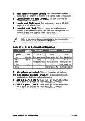
... port connects a headphone or a speaker. These two 4-pin Universal Serial Bus (USB) ports are available for the function of this port becomes Front Speaker Out. L i n e I n p o r t ( l i g h t b l u e ) . ASUS P5W64 WS Professional 2-29 This port connects the rear speakers on a 4-channel, 6-channel, or 8-channel audio configuration. 6 . Side Speaker Out - - Audio 2, 4, 6, or 8-channel configuration Port Light Blue Lime...
... port connects a headphone or a speaker. These two 4-pin Universal Serial Bus (USB) ports are available for the function of this port becomes Front Speaker Out. L i n e I n p o r t ( l i g h t b l u e ) . ASUS P5W64 WS Professional 2-29 This port connects the rear speakers on a 4-channel, 6-channel, or 8-channel audio configuration. 6 . Side Speaker Out - - Audio 2, 4, 6, or 8-channel configuration Port Light Blue Lime...

Motherboard Installation Guide
Page 57
... • Pin 20 on the IDE ribbon cable to prevent incorrect cable connection when using a FDD cable with a covered Pin 5. ASUS P5W64 WS Professional 2-31 Insert one of the floppy disk drive. Connect the blue connector to the motherboard's IDE connector, then select one end of ... signal connector at the back of the following modes to configure your device. ® P5W64 WS PRO PRI_IDE NOTE: Orient the red markings (usually zigzag) on the IDE connector is removed to PIN 1. ® P5W64 WS PRO 2.7.2 Internal connectors 1 . FLOPPY NOTE: Orient the red markings on each Ultra ...
... • Pin 20 on the IDE ribbon cable to prevent incorrect cable connection when using a FDD cable with a covered Pin 5. ASUS P5W64 WS Professional 2-31 Insert one of the floppy disk drive. Connect the blue connector to the motherboard's IDE connector, then select one end of ... signal connector at the back of the following modes to configure your device. ® P5W64 WS PRO PRI_IDE NOTE: Orient the red markings (usually zigzag) on the IDE connector is removed to PIN 1. ® P5W64 WS PRO 2.7.2 Internal connectors 1 . FLOPPY NOTE: Orient the red markings on each Ultra ...
Motherboard Installation Guide
Page 59
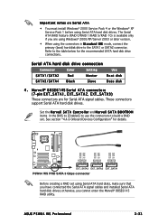
...connectors are using Windows® 2000/XP/Server 2003 or later version. • When using Serial ATA hard disk drives. ASUS P5W64 WS Professional 2-33 The Serial ATA RAID feature (RAID 0/RAID 1/RAID 5/RAID 10) is available only if you have connected the Serial...signal cables and installed Serial ATA hard disk drives; See section "4.4.6 Onboard Devices Configuration" for details. ® P5W64 WS PRO GND RSATA_TX_0_DP RSATA_TX_0_DN GND RSATA_RX_0_DN RSATA_RX_0_DP GND GND RSATA_TX_1_DP RSATA_TX_1_DN GND RSATA_RX_1_DN RSATA_RX_1_DP GND GND RSATA_TX_2_DP RSATA_TX_2_DN GND RSATA_RX_2_DN ...
...connectors are using Windows® 2000/XP/Server 2003 or later version. • When using Serial ATA hard disk drives. ASUS P5W64 WS Professional 2-33 The Serial ATA RAID feature (RAID 0/RAID 1/RAID 5/RAID 10) is available only if you have connected the Serial...signal cables and installed Serial ATA hard disk drives; See section "4.4.6 Onboard Devices Configuration" for details. ® P5W64 WS PRO GND RSATA_TX_0_DP RSATA_TX_0_DN GND RSATA_RX_0_DN RSATA_RX_0_DP GND GND RSATA_TX_1_DP RSATA_TX_1_DN GND RSATA_RX_1_DN RSATA_RX_1_DP GND GND RSATA_TX_2_DP RSATA_TX_2_DN GND RSATA_RX_2_DN ...


