
Motherboard Installation Guide
Page 17
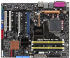
ASUS P5W64 WS Professional 1-1 Before you for up to 7 devices I/O shield ASUS motherboard support CD InterVideo® Media Launcher User guide If any of ASUS quality motherboards! Thank you start installing the motherboard, and hardware devices on it another standout in your... disk drive cable 1 x Ultra DMA 133/100/66 cable 7 x Serial ATA signal cables 4 x Serial ATA power cables for buying an ASUS® P5W64 WS Professional Workstation motherboard! The motherboard delivers a host of new features and latest technologies, making it , check the items in the long line of the above...
ASUS P5W64 WS Professional 1-1 Before you for up to 7 devices I/O shield ASUS motherboard support CD InterVideo® Media Launcher User guide If any of ASUS quality motherboards! Thank you start installing the motherboard, and hardware devices on it another standout in your... disk drive cable 1 x Ultra DMA 133/100/66 cable 7 x Serial ATA signal cables 4 x Serial ATA power cables for buying an ASUS® P5W64 WS Professional Workstation motherboard! The motherboard delivers a host of new features and latest technologies, making it , check the items in the long line of the above...
Motherboard Installation Guide
Page 19
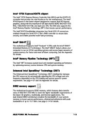
... system performance. The Intel® EM64T feature allows your system memory to boost system performance, eliminating bottlenecks with peak bandwidths of up to 10.7 GB/s. ASUS P5W64 WS Professional 1-3 Intel® 975X Express/ICH7R chipset The Intel® 975X Express Memory Controller Hub (MCH) and the ICH7R I /II connectors enabled through the Serial ATA...
... system performance. The Intel® EM64T feature allows your system memory to boost system performance, eliminating bottlenecks with peak bandwidths of up to 10.7 GB/s. ASUS P5W64 WS Professional 1-3 Intel® 975X Express/ICH7R chipset The Intel® 975X Express Memory Controller Hub (MCH) and the ICH7R I /II connectors enabled through the Serial ATA...
Motherboard Installation Guide
Page 21
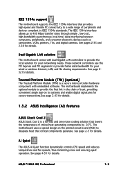
... convenient single sign-on the printed circuit board (PCB) to provide faster data bandwidth for your networking needs. AI Quiet The ASUS AI Quiet function dynamically controls CPU speed and reduces temperature and fan speeds, thus minimizing noise and ensuring quiet operation. Dual Gigabit...2 is a fan-less and zero-noise cooling solution that lowers the temperature of critical heat generating components by 20ºC. ASUS P5W64 WS Professional 1-5 These network controllers use the PCI Express and PCI segments to dissipate heat that critical components generate. See page 232 for...
... convenient single sign-on the printed circuit board (PCB) to provide faster data bandwidth for your networking needs. AI Quiet The ASUS AI Quiet function dynamically controls CPU speed and reduces temperature and fan speeds, thus minimizing noise and ensuring quiet operation. Dual Gigabit...2 is a fan-less and zero-noise cooling solution that lowers the temperature of critical heat generating components by 20ºC. ASUS P5W64 WS Professional 1-5 These network controllers use the PCI Express and PCI segments to dissipate heat that critical components generate. See page 232 for...
Motherboard Installation Guide
Page 23
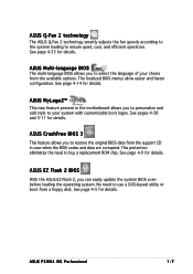
.... The localized BIOS menus allow easier and faster configuration. ASUS Multi-language BIOS The multi-language BIOS allows you to your choice from the available options. See page 4-5 for details. ASUS P5W64 WS Professional 1-7 This protection eliminates the need to ensure quiet, cool..., and efficient operation. ASUS Q-Fan 2 technology The ASUS Q-Fan 2 technology smartly adjusts the fan speeds according to the system loading...
.... The localized BIOS menus allow easier and faster configuration. ASUS Multi-language BIOS The multi-language BIOS allows you to your choice from the available options. See page 4-5 for details. ASUS P5W64 WS Professional 1-7 This protection eliminates the need to ensure quiet, cool..., and efficient operation. ASUS Q-Fan 2 technology The ASUS Q-Fan 2 technology smartly adjusts the fan speeds according to the system loading...
Motherboard Installation Guide
Page 26
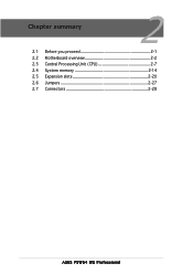
Chapter summary 2 2.1 Before you proceed 2-1 2.2 Motherboard overview 2-2 2.3 Central Processing Unit (CPU 2-7 2.4 System memory 2-14 2.5 Expansion slots 2-20 2.6 Jumpers 2-27 2.7 Connectors 2-28 ASUS P5W64 WS Professional
Chapter summary 2 2.1 Before you proceed 2-1 2.2 Motherboard overview 2-2 2.3 Central Processing Unit (CPU 2-7 2.4 System memory 2-14 2.5 Expansion slots 2-20 2.6 Jumpers 2-27 2.7 Connectors 2-28 ASUS P5W64 WS Professional
Motherboard Installation Guide
Page 27
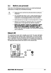
2.1 Before you proceed Take note of the onboard LED. ® P5W64 WS PRO SB_PWR ON Standby Power P5W64 WS PRO Onboard LED OFF Powered Off ASUS P5W64 WS Professional 2-1 This is a reminder that you should shut down the system and unplug the power cable before handling components to avoid damaging them due to static ...
2.1 Before you proceed Take note of the onboard LED. ® P5W64 WS PRO SB_PWR ON Standby Power P5W64 WS PRO Onboard LED OFF Powered Off ASUS P5W64 WS Professional 2-1 This is a reminder that you should shut down the system and unplug the power cable before handling components to avoid damaging them due to static ...
Motherboard Installation Guide
Page 29
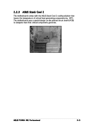
ASUS P5W64 WS Professional 2-3 The motherboard uses a special design on the printed circuit board (PCB) to dissipate heat that lowers the temperature of critical heat generating components by 20ºC. 2.2.3 ASUS Stack Cool 2 The motherboard comes with the ASUS Stack Cool 2 cooling solution that critical components generate.
ASUS P5W64 WS Professional 2-3 The motherboard uses a special design on the printed circuit board (PCB) to dissipate heat that lowers the temperature of critical heat generating components by 20ºC. 2.2.3 ASUS Stack Cool 2 The motherboard comes with the ASUS Stack Cool 2 cooling solution that critical components generate.
Motherboard Installation Guide
Page 33
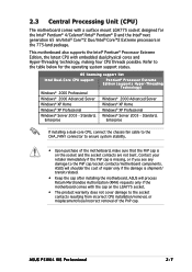
...® 2000 Advanced Server Windows® 2000 Advanced Server Windows® XP Home Windows® XP Home Windows® XP Professional Windows® XP Professional Windows® Server 2003 - ASUS P5W64 WS Professional 2-7 This motherboard also supports the Intel® Pentium® Processor Extreme Edition, the latest CPU with embedded dual physical cores and Hyper-Threading...
...® 2000 Advanced Server Windows® 2000 Advanced Server Windows® XP Home Windows® XP Home Windows® XP Professional Windows® XP Professional Windows® Server 2003 - ASUS P5W64 WS Professional 2-7 This motherboard also supports the Intel® Pentium® Processor Extreme Edition, the latest CPU with embedded dual physical cores and Hyper-Threading...

Motherboard Installation Guide
Page 35
... the load plate with the Intel® Enhanced Memory 64 Technology (EM64T), Enhanced Intel SpeedStep® Technology (EIST), and Hyper-Threading Technology. Refer to remove (B). ASUS P5W64 WS Professional 2-9 Position the CPU over the socket, making sure that the gold triangle is on these CPU features. If installing a dual-core CPU, connect the chassis...
... the load plate with the Intel® Enhanced Memory 64 Technology (EM64T), Enhanced Intel SpeedStep® Technology (EIST), and Hyper-Threading Technology. Refer to remove (B). ASUS P5W64 WS Professional 2-9 Position the CPU over the socket, making sure that the gold triangle is on these CPU features. If installing a dual-core CPU, connect the chassis...

Motherboard Installation Guide
Page 37
Push down two fasteners at a time in a diagonal sequence to plug this connector. Hardware monitoring errors can occur if you fail to secure the heatsink and fan assembly in place. CPU_FAN ® P5W64 WS PRO CPU FAN PWM CPU FAN IN CPU FAN PWR GND P5W64 WS PRO CPU fan connector Do not forget to the connector on the motherboard labeled CPU_FAN. A B A B A B B A 3. ASUS P5W64 WS Professional 2-11 Connect the CPU fan cable to connect the CPU fan connector! 2.
Push down two fasteners at a time in a diagonal sequence to plug this connector. Hardware monitoring errors can occur if you fail to secure the heatsink and fan assembly in place. CPU_FAN ® P5W64 WS PRO CPU FAN PWM CPU FAN IN CPU FAN PWR GND P5W64 WS PRO CPU fan connector Do not forget to the connector on the motherboard labeled CPU_FAN. A B A B A B B A 3. ASUS P5W64 WS Professional 2-11 Connect the CPU fan cable to connect the CPU fan connector! 2.
Motherboard Installation Guide
Page 39
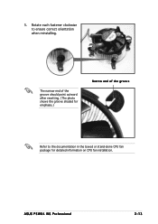
The narrow end of the groove should point outward after resetting. (The photo shows the groove shaded for emphasis.) Narrow end of the groove Refer to ensure correct orientation when reinstalling. ASUS P5W64 WS Professional 2-13 5. Rotate each fastener clockwise to the documentation in the boxed or stand-alone CPU fan package for detailed information on CPU fan installation.
The narrow end of the groove should point outward after resetting. (The photo shows the groove shaded for emphasis.) Narrow end of the groove Refer to ensure correct orientation when reinstalling. ASUS P5W64 WS Professional 2-13 5. Rotate each fastener clockwise to the documentation in the boxed or stand-alone CPU fan package for detailed information on CPU fan installation.
Motherboard Installation Guide
Page 41
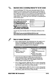
... Server Windows® Server 2003 Enterprise Edition 64-bit Windows® Server 2003 Standard x64 Edition Windows® XP Professional x64 Edition Windows® Server 2003 Enterprise x64 Edition • Some old-version DDR2-667 DIMMs may not match ...asus.com/pub/ASUS/mb/4GB_Rev1.pdf http://www.intel.com/support/motherboards/server/sb/cs-016594.htm Notes on the operating systems listed below for further explanation: http://support.asus.com/faq/ faq.aspx?SLanguage=en-us Under G e n e r a l s e a r c h, make the selections as shown, then click S e a r c h. ASUS P5W64 WS Professional...
... Server Windows® Server 2003 Enterprise Edition 64-bit Windows® Server 2003 Standard x64 Edition Windows® XP Professional x64 Edition Windows® Server 2003 Enterprise x64 Edition • Some old-version DDR2-667 DIMMs may not match ...asus.com/pub/ASUS/mb/4GB_Rev1.pdf http://www.intel.com/support/motherboards/server/sb/cs-016594.htm Notes on the operating systems listed below for further explanation: http://support.asus.com/faq/ faq.aspx?SLanguage=en-us Under G e n e r a l s e a r c h, make the selections as shown, then click S e a r c h. ASUS P5W64 WS Professional...
Motherboard Installation Guide
Page 43
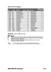
... 78.01092.420 SS M20EL5G3H3160B1C0Z SS M20AD5Q3H3163J1C52 SS TS64MLQ64V6J DS TS128MLQ64V6J S i d e ( s ): S S - Visit the ASUS website for the latest DDR2-800/667 MHz QVL. HY5PS12821AFP-Y5(ECC) - Engineering Sample - E5108AE-6E-E - AD29608A8B-3EG -... A - Supports one pair of Dual-channel memory configuration. Supports one module inserted into either slot, in Single-channel memory configuration. ASUS P5W64 WS Professional 2-17 HY5PS12821AFP-Y5(ECC) - C - DDR2-667 MHz capability Size Vendor 1024MB 1024MB 512MB 1024MB 512MB 512MB 1024MB 512MB 1024MB 512MB ...
... 78.01092.420 SS M20EL5G3H3160B1C0Z SS M20AD5Q3H3163J1C52 SS TS64MLQ64V6J DS TS128MLQ64V6J S i d e ( s ): S S - Visit the ASUS website for the latest DDR2-800/667 MHz QVL. HY5PS12821AFP-Y5(ECC) - Engineering Sample - E5108AE-6E-E - AD29608A8B-3EG -... A - Supports one pair of Dual-channel memory configuration. Supports one module inserted into either slot, in Single-channel memory configuration. ASUS P5W64 WS Professional 2-17 HY5PS12821AFP-Y5(ECC) - C - DDR2-667 MHz capability Size Vendor 1024MB 1024MB 512MB 1024MB 512MB 512MB 1024MB 512MB 1024MB 512MB ...
Motherboard Installation Guide
Page 45
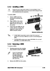
... DIMM. • The DDR2 DIMM sockets do so can cause severe damage to unlock the DIMM. Remove the DIMM from the socket. 2 1 DDR2 DIMM notch ASUS P5W64 WS Professional 2-19 Failure to do not support DDR DIMMs. Do not install DDR DIMMs to the DDR2 DIMM sockets. 2.4.4 Removing a DIMM To remove a DIMM: 1. 2.4.3 Installing a DIMM...
... DIMM. • The DDR2 DIMM sockets do so can cause severe damage to unlock the DIMM. Remove the DIMM from the socket. 2 1 DDR2 DIMM notch ASUS P5W64 WS Professional 2-19 Failure to do not support DDR DIMMs. Do not install DDR DIMMs to the DDR2 DIMM sockets. 2.4.4 Removing a DIMM To remove a DIMM: 1. 2.4.3 Installing a DIMM...
Motherboard Installation Guide
Page 47
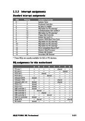
shared - - - - - - - - shared - - - - - - - - shared - - - - shared - - - - - IRQ assignments for ISA or PCI devices. shared - - shared - - --- shared - - - - - - - - shared shared shared - shared - - - - shared shared ASUS P5W64 WS Professional 2-21 shared - - - shared - - - - shared - - - - - - - - 2.5.3 Interrupt assignments Standard interrupt assignments IRQ Priority 0 1 1 2 2 - 3 11 4 12 5 13 6 14 7 15 8 3 9 4 10 5 11 6 12 7 13 8 14 9 15 10 Standard Function ...
shared - - - - - - - - shared - - - - - - - - shared - - - - shared - - - - - IRQ assignments for ISA or PCI devices. shared - - shared - - --- shared - - - - - - - - shared shared shared - shared - - - - shared shared ASUS P5W64 WS Professional 2-21 shared - - - shared - - - - shared - - - - - - - - 2.5.3 Interrupt assignments Standard interrupt assignments IRQ Priority 0 1 1 2 2 - 3 11 4 12 5 13 6 14 7 15 8 3 9 4 10 5 11 6 12 7 13 8 14 9 15 10 Standard Function ...
Motherboard Installation Guide
Page 49
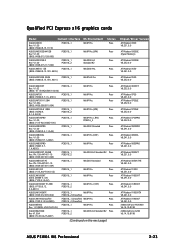
... V8.241.0.0 ATI Radeon X1900CF V8.241.0.0 nVIDIA GeForce PCX5900 V6.14.10.8198 nVIDIA GeForce 6200 V6.14.10.8198 ASUS P5W64 WS Professional 2-23 A901) ASUS EAX700-X 128M PCIEX16_1 WinXP Pro. V1.00 (BIOS: V554D.9.7.1.AS02) PCIEX16_1 WinXP Pro.(CHT) Pass... V5E4D.9. 8.1.4. PN: 109-A47401-10 (BIOS: V009.007.001.004) PCIEX16_1 PCIEX16_2 Win2003-64 Standard R2 Pass ASUS EAX850XT PE Rev. Pass (BIOS: V009.012.005.002) PCIEX16_2 (CrossFire) ASUS EAX1900CrossFire PCIEX16_1 (CrossFire) WinXP Pro. AS05) PCIEX16_1 OS Environment WinXP Pro. Status Pass Pass Pass Pass Chipset/Driver ...
... V8.241.0.0 ATI Radeon X1900CF V8.241.0.0 nVIDIA GeForce PCX5900 V6.14.10.8198 nVIDIA GeForce 6200 V6.14.10.8198 ASUS P5W64 WS Professional 2-23 A901) ASUS EAX700-X 128M PCIEX16_1 WinXP Pro. V1.00 (BIOS: V554D.9.7.1.AS02) PCIEX16_1 WinXP Pro.(CHT) Pass... V5E4D.9. 8.1.4. PN: 109-A47401-10 (BIOS: V009.007.001.004) PCIEX16_1 PCIEX16_2 Win2003-64 Standard R2 Pass ASUS EAX850XT PE Rev. Pass (BIOS: V009.012.005.002) PCIEX16_2 (CrossFire) ASUS EAX1900CrossFire PCIEX16_1 (CrossFire) WinXP Pro. AS05) PCIEX16_1 OS Environment WinXP Pro. Status Pass Pass Pass Pass Chipset/Driver ...
Motherboard Installation Guide
Page 53
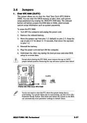
... battery. 5. To erase the RTC RAM: 1. For system failure due to overclocking. ASUS P5W64 WS Professional 2-27 Turn OFF the computer and unplug the power cord. 2. Removing the cap will cause system boot failure! ® P5W64 WS PRO CLRTC 12 23 Normal (Default) P5W64 WS PRO Clear RTC RAM Clear RTC You do not need to clear the...
... battery. 5. To erase the RTC RAM: 1. For system failure due to overclocking. ASUS P5W64 WS Professional 2-27 Turn OFF the computer and unplug the power cord. 2. Removing the cap will cause system boot failure! ® P5W64 WS PRO CLRTC 12 23 Normal (Default) P5W64 WS PRO Clear RTC RAM Clear RTC You do not need to clear the...
Motherboard Installation Guide
Page 55
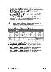
... Bus (USB) ports are available for connecting USB 2.0 devices. This port connects the center/subwoofer speakers. 7 . L i n e I n p o r t ( l i g h t b l u e ) . This port connects a headphone or a speaker. Side Speaker Out - - ASUS P5W64 WS Professional 2-29 This port connects the side speakers in 2, 4, 6, or 8-channel configuration. U S B 2 . 0 p o r t s 3 a n d 4 . These two 4-pin Universal Serial Bus (USB) ports are available for the function of...
... Bus (USB) ports are available for connecting USB 2.0 devices. This port connects the center/subwoofer speakers. 7 . L i n e I n p o r t ( l i g h t b l u e ) . This port connects a headphone or a speaker. Side Speaker Out - - ASUS P5W64 WS Professional 2-29 This port connects the side speakers in 2, 4, 6, or 8-channel configuration. U S B 2 . 0 p o r t s 3 a n d 4 . These two 4-pin Universal Serial Bus (USB) ports are available for the function of...

Motherboard Installation Guide
Page 57
...(133/)100/66 signal cable. Pin 5 on each Ultra DMA 133/100/66 signal cable: blue, black, and gray. PIN 1 P5W64 WS PRO Floppy disk drive connector 2 . ASUS P5W64 WS Professional 2-31 There are three connectors on the connector is for Ultra DMA 100/66 IDE devices. Primary IDE connector (40-1 pin PRI_IDE) ... disk drive connector (34-1 pin FLOPPY) This connector is removed to prevent incorrect cable connection when using a FDD cable with a covered Pin 5. P5W64 WS PRO IDE connector • Pin 20 on the IDE connector is for the provided floppy disk drive (FDD) signal cable.
...(133/)100/66 signal cable. Pin 5 on each Ultra DMA 133/100/66 signal cable: blue, black, and gray. PIN 1 P5W64 WS PRO Floppy disk drive connector 2 . ASUS P5W64 WS Professional 2-31 There are three connectors on the connector is for Ultra DMA 100/66 IDE devices. Primary IDE connector (40-1 pin PRI_IDE) ... disk drive connector (34-1 pin FLOPPY) This connector is removed to prevent incorrect cable connection when using a FDD cable with a covered Pin 5. P5W64 WS PRO IDE connector • Pin 20 on the IDE connector is for the provided floppy disk drive (FDD) signal cable.
Motherboard Installation Guide
Page 59
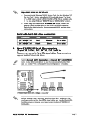
...connectors in the BIOS to [Enabled] to use the connectors to the table below for details. ® P5W64 WS PRO GND RSATA_TX_0_DP RSATA_TX_0_DN GND RSATA_RX_0_DN RSATA_RX_0_DP GND GND RSATA_TX_1_DP RSATA_TX_1_DN GND RSATA_RX_1_DN RSATA_RX_1_DP GND GND RSATA_TX_2_DP RSATA_TX_2_DN GND RSATA_RX_2_DN... These connectors support Serial ATA hard disk drives. Refer to build a RAID set using Serial ATA hard disk drives. ASUS P5W64 WS Professional 2-33 See section "4.4.6 Onboard Devices Configuration" for the recommended SATA hard disk drive connections. otherwise, you have connected the...
...connectors in the BIOS to [Enabled] to use the connectors to the table below for details. ® P5W64 WS PRO GND RSATA_TX_0_DP RSATA_TX_0_DN GND RSATA_RX_0_DN RSATA_RX_0_DP GND GND RSATA_TX_1_DP RSATA_TX_1_DN GND RSATA_RX_1_DN RSATA_RX_1_DP GND GND RSATA_TX_2_DP RSATA_TX_2_DN GND RSATA_RX_2_DN... These connectors support Serial ATA hard disk drives. Refer to build a RAID set using Serial ATA hard disk drives. ASUS P5W64 WS Professional 2-33 See section "4.4.6 Onboard Devices Configuration" for the recommended SATA hard disk drive connections. otherwise, you have connected the...


