User Guide
Page 1
P5CR-VM Motherboard
P5CR-VM Motherboard
User Guide
Page 3
... to find more information viii Conventions used in this guide ix Typography ix P5CR-VM specifications summary x Chapter 1: Product introduction 1.1 Welcome 1-1 1.2 Package contents 1-1 1.3 Special features 1-2 1.3.1 Product highlights 1-2 1.3.2 Innovative ASUS features 1-4 Chapter 2: Hardware information 2.1 Before you proceed 2-1 2.2 Motherboard overview 2-2 2.2.1 Placement direction 2-2 2.2.2 Screw holes 2-2 2.2.3 Motherboard layout 2-3 2.2.4 Layout contents 2-4 2.3 Central Processing Unit (CPU 2-6 2.3.1 Installing the CPU 2-6 2.3.2 Installing the...
... to find more information viii Conventions used in this guide ix Typography ix P5CR-VM specifications summary x Chapter 1: Product introduction 1.1 Welcome 1-1 1.2 Package contents 1-1 1.3 Special features 1-2 1.3.1 Product highlights 1-2 1.3.2 Innovative ASUS features 1-4 Chapter 2: Hardware information 2.1 Before you proceed 2-1 2.2 Motherboard overview 2-2 2.2.1 Placement direction 2-2 2.2.2 Screw holes 2-2 2.2.3 Motherboard layout 2-3 2.2.4 Layout contents 2-4 2.3 Central Processing Unit (CPU 2-6 2.3.1 Installing the CPU 2-6 2.3.2 Installing the...
User Guide
Page 7
...yourself. Do not place the product in your area. If you add a device. • Before connecting or removing signal cables from the motherboard, ensure that all the manuals that came with the product, contact a qualified service technician or your retailer. If you are not sure ... product, make sure all power cables from the existing system before the signal cables are connected. vii Operation safety • Before installing the motherboard and adding devices on a stable surface. • If you are using an adapter or extension cord. Safety information Electrical safety •...
...yourself. Do not place the product in your area. If you add a device. • Before connecting or removing signal cables from the motherboard, ensure that all the manuals that came with the product, contact a qualified service technician or your retailer. If you are not sure ... product, make sure all power cables from the existing system before the signal cables are connected. vii Operation safety • Before installing the motherboard and adding devices on a stable surface. • If you are using an adapter or extension cord. Safety information Electrical safety •...
User Guide
Page 8
...8226; Appendix: Reference information This appendix includes additional information that may refer to when configuring the motherboard. Where to find more information Refer to the ASUS contact information. 2. About this guide is organized This manual contains the following sources for additional... and software updates. 1. It includes description of the switches, jumpers, and connectors on ASUS hardware and software products. ASUS websites The ASUS website provides updated information on the motherboard. • Chapter 3: Powering up This chapter describes the power up sequence, the vocal...
...8226; Appendix: Reference information This appendix includes additional information that may refer to when configuring the motherboard. Where to find more information Refer to the ASUS contact information. 2. About this guide is organized This manual contains the following sources for additional... and software updates. 1. It includes description of the switches, jumpers, and connectors on ASUS hardware and software products. ASUS websites The ASUS website provides updated information on the motherboard. • Chapter 3: Powering up This chapter describes the power up sequence, the vocal...
User Guide
Page 13
This chapter describes the motherboard features and the new technologies it supports. 1Product introduction
This chapter describes the motherboard features and the new technologies it supports. 1Product introduction
User Guide
Page 15
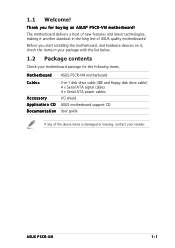
... list below. 1.2 Package contents Check your retailer. ASUS P5CR-VM 1-1 1.1 Welcome! Before you for the following items. M o t h e r b o a r d ASUS P5CR-VM motherboard Cables Accessory Application CD Documentation 2-in the long line of the above items is damaged or missing, contact your motherboard package for buying an ASUS® P5CR-VM motherboard! Thank you start installing the motherboard, and hardware devices on it another standout...
... list below. 1.2 Package contents Check your retailer. ASUS P5CR-VM 1-1 1.1 Welcome! Before you for the following items. M o t h e r b o a r d ASUS P5CR-VM motherboard Cables Accessory Application CD Documentation 2-in the long line of the above items is damaged or missing, contact your motherboard package for buying an ASUS® P5CR-VM motherboard! Thank you start installing the motherboard, and hardware devices on it another standout...
User Guide
Page 16
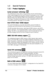
...and Intel® ICH6R I /O controller hub that provides bridging functions for four Serial ATA connectors. DDR2 533/400 memory support The motherboard supports DDR2 memory, which features data transfer rates of 533/400 MHz to meet the higher bandwidth requirements of up to 8.5 GB/s. ... 775-pin surface mount Land Grid Array (LGA) socket designed for details. See page 2-26 for details. 1-2 Chapter 1: Product introduction The motherboard also supports the Intel® Hyper-Threading technology and is a new generation server class I /O controller hub (ICH) provide the vital interfaces for...
...and Intel® ICH6R I /O controller hub that provides bridging functions for four Serial ATA connectors. DDR2 533/400 memory support The motherboard supports DDR2 memory, which features data transfer rates of 533/400 MHz to meet the higher bandwidth requirements of up to 8.5 GB/s. ... 775-pin surface mount Land Grid Array (LGA) socket designed for details. See page 2-26 for details. 1-2 Chapter 1: Product introduction The motherboard also supports the Intel® Hyper-Threading technology and is a new generation server class I /O controller hub (ICH) provide the vital interfaces for...

User Guide
Page 17
... with USB 1.1. Temperature, fan, and voltage monitoring The CPU temperature is backward compatible with existing PCI specifications. USB 2.0 is monitored by carrying data in packets. ASUS P5CR-VM 1-3 PCI Express™ interface The motherboard fully supports PCI Express, the latest I/O interconnect technology that speeds up the PCI bus.
... with USB 1.1. Temperature, fan, and voltage monitoring The CPU temperature is backward compatible with existing PCI specifications. USB 2.0 is monitored by carrying data in packets. ASUS P5CR-VM 1-3 PCI Express™ interface The motherboard fully supports PCI Express, the latest I/O interconnect technology that speeds up the PCI bus.
User Guide
Page 18
... the BIOS codes and data are corrupted. See page 4-5 for details. No need to ensure quiet, cool, and efficient operation. ASUS EZ Flash BIOS With the ASUS EZ Flash, you to personalize and add style to update the motherboard BIOS through a user-friendly interface. See page 4-8 for your system with customizable boot logos...
... the BIOS codes and data are corrupted. See page 4-5 for details. No need to ensure quiet, cool, and efficient operation. ASUS EZ Flash BIOS With the ASUS EZ Flash, you to personalize and add style to update the motherboard BIOS through a user-friendly interface. See page 4-8 for your system with customizable boot logos...
User Guide
Page 19
This chapter lists the hardware setup procedures that you have to perform when installing system components. It includes description of the jumpers and connectors on the motherboard. 2 Hardware information
This chapter lists the hardware setup procedures that you have to perform when installing system components. It includes description of the jumpers and connectors on the motherboard. 2 Hardware information
User Guide
Page 20
Chapter summary 2 2.1 Before you proceed 2-1 2.2 Motherboard overview 2-2 2.3 Central Processing Unit (CPU 2-6 2.4 System memory 2-13 2.5 Expansion slots 2-15 2.6 Jumpers 2-18 2.7 Connectors 2-23 ASUS P5CR-VM
Chapter summary 2 2.1 Before you proceed 2-1 2.2 Motherboard overview 2-2 2.3 Central Processing Unit (CPU 2-6 2.4 System memory 2-13 2.5 Expansion slots 2-15 2.6 Jumpers 2-18 2.7 Connectors 2-23 ASUS P5CR-VM
User Guide
Page 21
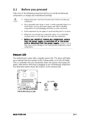
... LED. The illustration below shows the location of the following precautions before you install or remove any motherboard component. P5CR-VM P5CR-VM Onboard LED SB_PWR1 ON Standby Power OFF Powered Off ASUS P5CR-VM 2-1 The green LED lights up to indicate that the system is ON, in sleep mode, or... in any component, ensure that came with a standby power LED. This is switched off mode. Onboard LED The motherboard comes with the component. &#...
... LED. The illustration below shows the location of the following precautions before you install or remove any motherboard component. P5CR-VM P5CR-VM Onboard LED SB_PWR1 ON Standby Power OFF Powered Off ASUS P5CR-VM 2-1 The green LED lights up to indicate that the system is ON, in sleep mode, or... in any component, ensure that came with a standby power LED. This is switched off mode. Onboard LED The motherboard comes with the component. &#...
User Guide
Page 22
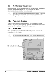
... you physical injury and damage motherboard components. 2.2.1 Placement direction When installing the motherboard, make sure that the motherboard fits into it into the holes indicated by circles to secure the motherboard to unplug the chassis power cord before installing the motherboard. Place this side towards the rear of the chassis P5CR-VM 2-2 Chapter 2: Hardware information The edge...
... you physical injury and damage motherboard components. 2.2.1 Placement direction When installing the motherboard, make sure that the motherboard fits into it into the holes indicated by circles to secure the motherboard to unplug the chassis power cord before installing the motherboard. Place this side towards the rear of the chassis P5CR-VM 2-2 Chapter 2: Hardware information The edge...

User Guide
Page 23
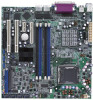
25cm (9.8in) 2.2.3 Motherboard layout PS/2KBMS KBPWR1 T: Mouse B: Keyboard USB12 USBPW12 ATXPWR1 PSUSMB1 25cm (9.8in) FM_CPU1 CPU_FAN1 COM1 Intel® E7221 LGA775 ATX12V1 PARALLEL PORT VGA1 LAN1 DDR2 ... CMOS Power CLRTC1 PCIE1 Intel ® ICH6R RECOVERY1 FRNT_FAN1 Broadcom BCM5721 REAR_FAN1 LAN_EN2 Super I/O REAR_FAN2 PCI1 PCI2 COM2 BPSMB1 USBPW56 USBPW78 USBPW34 8Mbit Flash BIOS P5CR-VM TRPWR1 FRNT_FAN2 BMCSOCKET1 FLOPPY1 USB34 USB56 USB78 HDLED1 BMCCONN1 PANEL1 AUX_PANEL1 SB_PWR1 SATA1 SATA2 SATA3 SATA4 ASUS P5CR-VM 2-3
25cm (9.8in) 2.2.3 Motherboard layout PS/2KBMS KBPWR1 T: Mouse B: Keyboard USB12 USBPW12 ATXPWR1 PSUSMB1 25cm (9.8in) FM_CPU1 CPU_FAN1 COM1 Intel® E7221 LGA775 ATX12V1 PARALLEL PORT VGA1 LAN1 DDR2 ... CMOS Power CLRTC1 PCIE1 Intel ® ICH6R RECOVERY1 FRNT_FAN1 Broadcom BCM5721 REAR_FAN1 LAN_EN2 Super I/O REAR_FAN2 PCI1 PCI2 COM2 BPSMB1 USBPW56 USBPW78 USBPW34 8Mbit Flash BIOS P5CR-VM TRPWR1 FRNT_FAN2 BMCSOCKET1 FLOPPY1 USB34 USB56 USB78 HDLED1 BMCCONN1 PANEL1 AUX_PANEL1 SB_PWR1 SATA1 SATA2 SATA3 SATA4 ASUS P5CR-VM 2-3
User Guide
Page 26
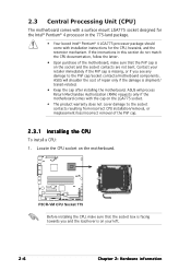
... not bent. ASUS will process Return Merchandise Authorization (RMA) requests only if the motherboard comes with installation instructions for the Intel® Pentium® 4 processor in this section do not match the CPU documentation, follow the latter. • Upon purchase of the PnP cap. 2.3.1 Installing the CPU To install a CPU: 1. P5CR-VM P5CR-VM CPU Socket...
... not bent. ASUS will process Return Merchandise Authorization (RMA) requests only if the motherboard comes with installation instructions for the Intel® Pentium® 4 processor in this section do not match the CPU documentation, follow the latter. • Upon purchase of the PnP cap. 2.3.1 Installing the CPU To install a CPU: 1. P5CR-VM P5CR-VM CPU Socket...
User Guide
Page 28
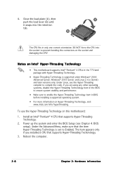
6. DO NOT force the CPU into the retention tab. To use the Hyper-Threading compiler to prevent bending the connectors on this motherboard: 1. Power up the system and enter the BIOS Setup (see Chapter 4: BIOS setup). The item appears only if you are ...-Threading Technology item in BIOS before installing a supported operating system. • For more information on Intel® Hyper-Threading Technology • This motherboard supports Intel® Pentium® 4 CPUs in only one correct orientation. Notes on Hyper-Threading Technology, visit www.intel.com/info/hyperthreading. Reboot...
6. DO NOT force the CPU into the retention tab. To use the Hyper-Threading compiler to prevent bending the connectors on this motherboard: 1. Power up the system and enter the BIOS Setup (see Chapter 4: BIOS setup). The item appears only if you are ...-Threading Technology item in BIOS before installing a supported operating system. • For more information on Intel® Hyper-Threading Technology • This motherboard supports Intel® Pentium® 4 CPUs in only one correct orientation. Notes on Hyper-Threading Technology, visit www.intel.com/info/hyperthreading. Reboot...

User Guide
Page 29
... that you install the CPU fan and heatsink assembly. Visit the ASUS website for (www.asus.com) for emphasis.) ASUS P5CR-VM 2-9 Place the heatsink on top of the installed CPU, making sure that you have installed the motherboard to the chassis before you have properly applied Thermal Interface Material to...groove pointing outward. (The photo shows the groove shaded for the updated list of the groove Motherboard hole Fastener Make sure to the CPU heatsink or CPU before you use ASUS-certified multi-directional heatsink and fan. Make sure that the four fasteners match the holes on...
... that you install the CPU fan and heatsink assembly. Visit the ASUS website for (www.asus.com) for emphasis.) ASUS P5CR-VM 2-9 Place the heatsink on top of the installed CPU, making sure that you have installed the motherboard to the chassis before you have properly applied Thermal Interface Material to...groove pointing outward. (The photo shows the groove shaded for the updated list of the groove Motherboard hole Fastener Make sure to the CPU heatsink or CPU before you use ASUS-certified multi-directional heatsink and fan. Make sure that the four fasteners match the holes on...
User Guide
Page 30
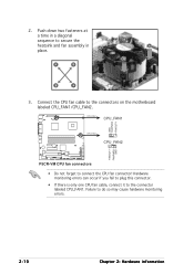
... CPU fan cable, connect it to the connectors on the motherboard labeled CPU_FAN1/CPU_FAN2. 2. Connect the CPU fan cable to the connector labeled CPU_FAN1. Push down two fasteners at a time in A place. CPU_FAN1 CPU_FAN1 GND FANPWR2 FANOUT4 CPU_FAN2 CPU_FAN2 FANOUT7 FANPWR3 GND P5CR-VM P5CR-VM CPU fan connectors • Do not forget to secure...
... CPU fan cable, connect it to the connectors on the motherboard labeled CPU_FAN1/CPU_FAN2. 2. Connect the CPU fan cable to the connector labeled CPU_FAN1. Push down two fasteners at a time in A place. CPU_FAN1 CPU_FAN1 GND FANPWR2 FANOUT4 CPU_FAN2 CPU_FAN2 FANOUT7 FANPWR3 GND P5CR-VM P5CR-VM CPU fan connectors • Do not forget to secure...

User Guide
Page 31
Rotate each fastener counterclockwise. 3. Pull up two fasteners at a time in a diagonal sequence to disengage the heatsink B and fan assembly from the connector on the motherboard. 2. A B A B B A ASUS P5CR-VM 2-11 2.3.3 Uninstalling the CPU heatsink and fan To uninstall the CPU heatsink and fan: 1. Disconnect the CPU fan cable from the A motherboard.
Rotate each fastener counterclockwise. 3. Pull up two fasteners at a time in a diagonal sequence to disengage the heatsink B and fan assembly from the connector on the motherboard. 2. A B A B B A ASUS P5CR-VM 2-11 2.3.3 Uninstalling the CPU heatsink and fan To uninstall the CPU heatsink and fan: 1. Disconnect the CPU fan cable from the A motherboard.
User Guide
Page 32
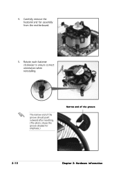
The narrow end of the groove should point outward after resetting. (The photo shows the groove shaded for emphasis.) Narrow end of the groove 2-12 Chapter 2: Hardware information Rotate each fastener clockwise to ensure correct orientation when reinstalling. 4. Carefully remove the heatsink and fan assembly from the motherboard. 5.
The narrow end of the groove should point outward after resetting. (The photo shows the groove shaded for emphasis.) Narrow end of the groove 2-12 Chapter 2: Hardware information Rotate each fastener clockwise to ensure correct orientation when reinstalling. 4. Carefully remove the heatsink and fan assembly from the motherboard. 5.


