Motherboard DIY Troubleshooting Guide
Page 8
...guide is organized This manual contains the following parts: • Chapter 1: Product introduction This chapter describes the features of the P4B-LS motherboard. Detailed descriptions of the BIOS parameters are also provided. • Chapter 5: Software support This chapter describes the contents of...technology it supports. • Chapter 2: Hardware information This chapter lists the hardware setup procedures that you need when installing the ASUS P4B-LS motherboard. It includes brief descriptions of the special attributes of the support CD that comes with the motherboard package. •...
...guide is organized This manual contains the following parts: • Chapter 1: Product introduction This chapter describes the features of the P4B-LS motherboard. Detailed descriptions of the BIOS parameters are also provided. • Chapter 5: Software support This chapter describes the contents of...technology it supports. • Chapter 2: Hardware information This chapter lists the hardware setup procedures that you need when installing the ASUS P4B-LS motherboard. It includes brief descriptions of the special attributes of the support CD that comes with the motherboard package. •...

Motherboard DIY Troubleshooting Guide
Page 12
ASUS P4B-LS motherboard
ASUS P4B-LS motherboard
Motherboard DIY Troubleshooting Guide
Page 13
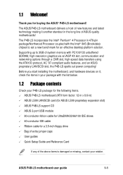
... with the list below. 1.2 Package contents Check your P4B-LS package for the following items. ASUS P4B-LS motherboard (ATX form factor: 12-in x 8.6-in) ASUS LS99 LAN/SCSI card (for ASUS LS99 proprietary expansion slot) ASUS P4B-LS support CD ASUS 2-port USB module 80-conductor ribbon cable for UltraDMA/...33/66/100 IDE drives 40-conductor IDE cable Ribbon cable for buying the ASUS® P4B-LS motherboard! 1.1 Welcome! The ASUS P4B-LS motherboard delivers a host of the above items is damaged or missing, contact your package with PC100/133 unbuffered...
... with the list below. 1.2 Package contents Check your P4B-LS package for the following items. ASUS P4B-LS motherboard (ATX form factor: 12-in x 8.6-in) ASUS LS99 LAN/SCSI card (for ASUS LS99 proprietary expansion slot) ASUS P4B-LS support CD ASUS 2-port USB module 80-conductor ribbon cable for UltraDMA/...33/66/100 IDE drives 40-conductor IDE cable Ribbon cable for buying the ASUS® P4B-LS motherboard! 1.1 Welcome! The ASUS P4B-LS motherboard delivers a host of the above items is damaged or missing, contact your package with PC100/133 unbuffered...
Motherboard DIY Troubleshooting Guide
Page 15
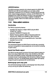
... 100MHz up to 200MHz at 1MHz increments • optimized system performance through the sophisticated SD and MS devices. ASUS P4B-LS motherboard user guide 1-3 LAN/SCSI interface The ASUS proprietary expansion slot onboard supports the ASUS LS99 LAN/SCSI card. The Smart Card Reader promotes cutting-edge technology featuring increased security for authenticating online transactions...
... 100MHz up to 200MHz at 1MHz increments • optimized system performance through the sophisticated SD and MS devices. ASUS P4B-LS motherboard user guide 1-3 LAN/SCSI interface The ASUS proprietary expansion slot onboard supports the ASUS LS99 LAN/SCSI card. The Smart Card Reader promotes cutting-edge technology featuring increased security for authenticating online transactions...
Motherboard DIY Troubleshooting Guide
Page 17
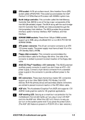
... interconnected through the Intel proprietary Hub interface. This 20-pin connector connects to prevent incorrect insertion of the Intel 845 (Brookdale) chipset. This ASUS patented auxilliary power connector is one of the two major components of the IDE ribbon cable. 8 AGP slot. The power supply must have ... the Intel Memory Controller Hub (MCH) is used if you don't have at least 1A on PCB R1.05 or later versions.) ASUS P4B-LS motherboard user guide 1-5 The MCH along with 400MHz system bus. 2 North bridge controller. 1 CPU socket. This controller called mPGA478 B.
... interconnected through the Intel proprietary Hub interface. This 20-pin connector connects to prevent incorrect insertion of the Intel 845 (Brookdale) chipset. This ASUS patented auxilliary power connector is one of the two major components of the IDE ribbon cable. 8 AGP slot. The power supply must have ... the Intel Memory Controller Hub (MCH) is used if you don't have at least 1A on PCB R1.05 or later versions.) ASUS P4B-LS motherboard user guide 1-5 The MCH along with 400MHz system bus. 2 North bridge controller. 1 CPU socket. This controller called mPGA478 B.

Motherboard DIY Troubleshooting Guide
Page 19
... Microphone jack. This Line Out (lime) jack connects a headphone or a speaker. 25 Game/MIDI connector. Retention Module Base Figure 1-2 Pre-installed Heatsink Retention Module Base ASUS P4B-LS motherboard user guide 1-7 This Mic (pink) jack connects a microphone. 23 Line In jack. This 25-pin port connects a parallel printer, a scanner, or other serial devices...
... Microphone jack. This Line Out (lime) jack connects a headphone or a speaker. 25 Game/MIDI connector. Retention Module Base Figure 1-2 Pre-installed Heatsink Retention Module Base ASUS P4B-LS motherboard user guide 1-7 This Mic (pink) jack connects a microphone. 23 Line In jack. This 25-pin port connects a parallel printer, a scanner, or other serial devices...

Motherboard DIY Troubleshooting Guide
Page 22
ASUS P4B-LS motherboard
ASUS P4B-LS motherboard

Motherboard DIY Troubleshooting Guide
Page 23
... not overtighten the screws! The edge with external ports goes to the rear part of the chassis Figure 2-1 Motherboard placement and screw holes ASUS P4B-LS motherboard user guide 2-1 Make sure to the image below. 2.1.2 Screw holes Place six (6) screws into it into the chassis in the ...the motherboard fits into the holes indicated by circles to secure the motherboard to the chassis. 2.1 Motherboard installation Before you place it . The P4B-LS uses the ATX form factor that measures 12 inches x 8.6 inches, a standard fit for most chassis. Refer to unplug the power cord before...
... not overtighten the screws! The edge with external ports goes to the rear part of the chassis Figure 2-1 Motherboard placement and screw holes ASUS P4B-LS motherboard user guide 2-1 Make sure to the image below. 2.1.2 Screw holes Place six (6) screws into it into the chassis in the ...the motherboard fits into the holes indicated by circles to secure the motherboard to the chassis. 2.1 Motherboard installation Before you place it . The P4B-LS uses the ATX form factor that measures 12 inches x 8.6 inches, a standard fit for most chassis. Refer to unplug the power cord before...

Motherboard DIY Troubleshooting Guide
Page 25
... severe damage to touch the ICs on PCB R1.05 and later versions.) WARNING ® P4B-LS ON Incorrect AGP Card OFF Correct AGP Card LED1 P4B-LS Onboard LED Figure 2-3 Onboard LEDs ON Standby Power OFF Powered Off ASUS P4B-LS motherboard user guide 2-3 Before you plug in soft-off or the power cord is present...
... severe damage to touch the ICs on PCB R1.05 and later versions.) WARNING ® P4B-LS ON Incorrect AGP Card OFF Correct AGP Card LED1 P4B-LS Onboard LED Figure 2-3 Onboard LEDs ON Standby Power OFF Powered Off ASUS P4B-LS motherboard user guide 2-3 Before you plug in soft-off or the power cord is present...
Motherboard DIY Troubleshooting Guide
Page 27
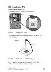
Locate the 478-pin ZIF socket on the motherboard. Socket Lever 90 - 100 Figure 2-6 CPU Socket Lever at 90° -100° Angle Make sure that the socket lever is lifted up to a 90°-100° angle. ASUS P4B-LS motherboard user guide 2-5 Figure 2-5 Intel 478-pin ZIF Socket 2. Unlock the socket by pressing the lever sideways, then lift it up to install a CPU. 1. 2.4.2 Installing the CPU Follow these steps to 90°-100° angle, otherwise the CPU does not fit in completely.
Locate the 478-pin ZIF socket on the motherboard. Socket Lever 90 - 100 Figure 2-6 CPU Socket Lever at 90° -100° Angle Make sure that the socket lever is lifted up to a 90°-100° angle. ASUS P4B-LS motherboard user guide 2-5 Figure 2-5 Intel 478-pin ZIF Socket 2. Unlock the socket by pressing the lever sideways, then lift it up to install a CPU. 1. 2.4.2 Installing the CPU Follow these steps to 90°-100° angle, otherwise the CPU does not fit in completely.
Motherboard DIY Troubleshooting Guide
Page 29
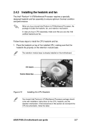
... 2-9 Installing the CPU Heatsink Your boxed Intel Pentium 4 478/Northwood Processor package should come with installation instructions for the CPU, heatsink, and the retention mechanism. ASUS P4B-LS motherboard user guide 2-7 In case you buy a CPU separately, make sure that the heatsink fits properly on the motherboard. When you use only Intel certified...
... 2-9 Installing the CPU Heatsink Your boxed Intel Pentium 4 478/Northwood Processor package should come with installation instructions for the CPU, heatsink, and the retention mechanism. ASUS P4B-LS motherboard user guide 2-7 In case you buy a CPU separately, make sure that the heatsink fits properly on the motherboard. When you use only Intel certified...

Motherboard DIY Troubleshooting Guide
Page 31
Hardware monitoring errors may occur if you fail to the module base. 3. Push down the locks on the motherboard labeled CPU_FAN. ASUS P4B-LS motherboard user guide 2-9 When secure, the retention locks should point to the connector on the retention mechanism to secure the heatsink and fan to plug ...
Hardware monitoring errors may occur if you fail to the module base. 3. Push down the locks on the motherboard labeled CPU_FAN. ASUS P4B-LS motherboard user guide 2-9 When secure, the retention locks should point to the connector on the retention mechanism to secure the heatsink and fan to plug ...
Motherboard DIY Troubleshooting Guide
Page 33
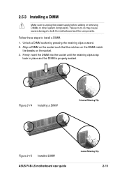
... until the retaining clips snap back in place and the DIMM is properly seated. Figure 2-14 Installing a DIMM Unlocked Retaining Clip Figure 2-15 Installed DIMM ASUS P4B-LS motherboard user guide Locked Retaining Clip 2-11 Follow these steps to both the motherboard and the components. Align a DIMM on the socket such that the...
... until the retaining clips snap back in place and the DIMM is properly seated. Figure 2-14 Installing a DIMM Unlocked Retaining Clip Figure 2-15 Installed DIMM ASUS P4B-LS motherboard user guide Locked Retaining Clip 2-11 Follow these steps to both the motherboard and the components. Align a DIMM on the socket such that the...
Motherboard DIY Troubleshooting Guide
Page 35
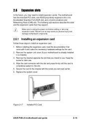
The motherboard has five standard PCI slots, one ASUS proprietary expansion slot, one Accelerated Graphics Port (AGP) slot, and a Communications and Networking Riser (CNR) slot. Make sure to unplug the power cord before adding .... 5. Keep the screw for the card. 2. Failure to do so may need to install expansion cards. Replace the system cover. Figure 2-17 Installed PCI Card ASUS P4B-LS motherboard user guide 2-13 Before installing the expansion card, read the documentation that you may cause you removed earlier. 6. Align the card connector with it...
The motherboard has five standard PCI slots, one ASUS proprietary expansion slot, one Accelerated Graphics Port (AGP) slot, and a Communications and Networking Riser (CNR) slot. Make sure to unplug the power cord before adding .... 5. Keep the screw for the card. 2. Failure to do so may need to install expansion cards. Replace the system cover. Figure 2-17 Installed PCI Card ASUS P4B-LS motherboard user guide 2-13 Before installing the expansion card, read the documentation that you may cause you removed earlier. 6. Align the card connector with it...

Motherboard DIY Troubleshooting Guide
Page 37
... to the user's manual that came with the card for 1.5V P4B-LS Accelerated Graphics Port (AGP) Slot Figure 2-19 Accelerated Graphics Port (AGP) Slot Location ASUS P4B-LS motherboard user guide 2-15 2.6.3 PCI slots and ASUS proprietary slot There are five standard 32-bit PCI slots and an... ASUS proprietary LAN/SCSI slot in this motherboard. Refer to ensure that supports +1.5V...
... to the user's manual that came with the card for 1.5V P4B-LS Accelerated Graphics Port (AGP) Slot Figure 2-19 Accelerated Graphics Port (AGP) Slot Location ASUS P4B-LS motherboard user guide 2-15 2.6.3 PCI slots and ASUS proprietary slot There are five standard 32-bit PCI slots and an... ASUS proprietary LAN/SCSI slot in this motherboard. Refer to ensure that supports +1.5V...

Motherboard DIY Troubleshooting Guide
Page 39
... through the DIP switches. The illustration below shows all the DIP switches to use the DIP switches. SWITCH OFF ON ON 1 2 3 4 5 6 7 8 9 10 ® P4B-LS P4B-LS DIP Switches Figure 2-21 DIP Switches 1. Frequency Selection 10. Frequency Multiple 3. Frequency Selection 6. Frequency Selection 9. JumperFree™ mode (JEN) This jumper allows you wish to... OFF. Frequency Multiple 5. The white block represents the switch position. Frequency Selection 7. Reserved The JEN jumper must be set in the OFF position. ASUS P4B-LS motherboard user guide 2-17
... through the DIP switches. The illustration below shows all the DIP switches to use the DIP switches. SWITCH OFF ON ON 1 2 3 4 5 6 7 8 9 10 ® P4B-LS P4B-LS DIP Switches Figure 2-21 DIP Switches 1. Frequency Selection 10. Frequency Multiple 3. Frequency Selection 6. Frequency Selection 9. JumperFree™ mode (JEN) This jumper allows you wish to... OFF. Frequency Multiple 5. The white block represents the switch position. Frequency Selection 7. Reserved The JEN jumper must be set in the OFF position. ASUS P4B-LS motherboard user guide 2-17
Motherboard DIY Troubleshooting Guide
Page 41
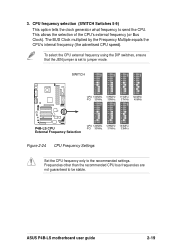
ASUS P4B-LS motherboard user guide 2-19 This allows the selection of the CPU's external frequency (or Bus Clock). The BUS Clock multiplied by the Frequency Multiple equals ... CPU speed). SWITCH ON 1 2 3 4 5 6 7 8 9 10 ON 1 2 3 4 5 6 7 8 9 10 ON 1 2 3 4 5 6 7 8 9 10 ON 1 2 3 4 5 6 7 8 9 10 CPU 100MHz 105MHz 111MHz 120MHz PCI 33MHz 35MHz 37MHz 40MHz ® P4B-LS ON 1 2 3 4 5 6 7 8 9 10 ON 1 2 3 4 5 6 7 8 9 10 ON 1 2 3 4 5 6 7 8 9 10 P4B-LS CPU External Frequency Selection CPU 120MHz 125MHz 133MHz PCI 30MHz 31MHz 33MHz Figure 2-24 CPU Frequency Settings Set the CPU frequency only...
ASUS P4B-LS motherboard user guide 2-19 This allows the selection of the CPU's external frequency (or Bus Clock). The BUS Clock multiplied by the Frequency Multiple equals ... CPU speed). SWITCH ON 1 2 3 4 5 6 7 8 9 10 ON 1 2 3 4 5 6 7 8 9 10 ON 1 2 3 4 5 6 7 8 9 10 ON 1 2 3 4 5 6 7 8 9 10 CPU 100MHz 105MHz 111MHz 120MHz PCI 33MHz 35MHz 37MHz 40MHz ® P4B-LS ON 1 2 3 4 5 6 7 8 9 10 ON 1 2 3 4 5 6 7 8 9 10 ON 1 2 3 4 5 6 7 8 9 10 P4B-LS CPU External Frequency Selection CPU 120MHz 125MHz 133MHz PCI 30MHz 31MHz 33MHz Figure 2-24 CPU Frequency Settings Set the CPU frequency only...
Motherboard DIY Troubleshooting Guide
Page 43
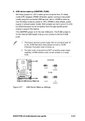
... can connect to wake up the computer from S3 sleep mode (no power to support this feature. Otherwise, the system does not power up Settings ASUS P4B-LS motherboard user guide 2-21 This feature requires a power supply that you can provide at least 1A on the +5VSB lead when these jumpers to ... running in low power mode) using the connected USB devices. The USBPWR jumper is for the rear USB ports. USBPWR ® P4B-LS 12 23 +5VSB +5V (Default) FUSB 12 23 P4B-LS USB Device Wake Up +5VSB +5V (Default) Figure 2-27 USB Device Wake-up . 2. Set to +5VSB to wake up (USBPWR,...
... can connect to wake up the computer from S3 sleep mode (no power to support this feature. Otherwise, the system does not power up Settings ASUS P4B-LS motherboard user guide 2-21 This feature requires a power supply that you can provide at least 1A on the +5VSB lead when these jumpers to ... running in low power mode) using the connected USB devices. The USBPWR jumper is for the rear USB ports. USBPWR ® P4B-LS 12 23 +5VSB +5V (Default) FUSB 12 23 P4B-LS USB Device Wake Up +5VSB +5V (Default) Figure 2-27 USB Device Wake-up . 2. Set to +5VSB to wake up (USBPWR,...

Motherboard DIY Troubleshooting Guide
Page 45
...RTC) RAM in CMOS, that you to the CPU. Remove the battery. 3. Remove the jumper cap. 4. 9. OVER_VOLT 12 23 ® P4B-LS Disable (Default) Enable P4B-LS OVER_VOLT Setting 10. Re-install the battery. 5. Refer to 1.75V range for a few seconds to re-enter data. It is present on... jumper allows you keep the default setting (Disable). Hold down the key during the boot process and enter BIOS setup to short the jumper. ASUS P4B-LS motherboard user guide 2-23 The RAM data in CMOS. To erase the RTC RAM: 1. Plug the power cord and turn ON the computer....
...RTC) RAM in CMOS, that you to the CPU. Remove the battery. 3. Remove the jumper cap. 4. 9. OVER_VOLT 12 23 ® P4B-LS Disable (Default) Enable P4B-LS OVER_VOLT Setting 10. Re-install the battery. 5. Refer to 1.75V range for a few seconds to re-enter data. It is present on... jumper allows you keep the default setting (Disable). Hold down the key during the boot process and enter BIOS setup to short the jumper. ASUS P4B-LS motherboard user guide 2-23 The RAM data in CMOS. To erase the RTC RAM: 1. Plug the power cord and turn ON the computer....
Motherboard DIY Troubleshooting Guide
Page 47
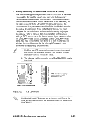
...with two ribbon cables - Secondary IDE Connector Primary IDE Connector ® P4B-LS NOTE: Orient the red markings (usually zigzag) on the UltraDMA/100/66 cable is removed to the UltraDMA/100/66 master device. ASUS P4B-LS motherboard user guide 2-25 Primary/Secondary IDE connectors (40-1 pin IDE1.../IDE2) This connector supports the provided UltraDMA/100/66 IDE hard disk ribbon cable. P4B-LS IDE Connectors PIN 1 Figure 2-32 IDE Connectors For ...
...with two ribbon cables - Secondary IDE Connector Primary IDE Connector ® P4B-LS NOTE: Orient the red markings (usually zigzag) on the UltraDMA/100/66 cable is removed to the UltraDMA/100/66 master device. ASUS P4B-LS motherboard user guide 2-25 Primary/Secondary IDE connectors (40-1 pin IDE1.../IDE2) This connector supports the provided UltraDMA/100/66 IDE hard disk ribbon cable. P4B-LS IDE Connectors PIN 1 Figure 2-32 IDE Connectors For ...


