Motherboard DIY Troubleshooting Guide
Page 13
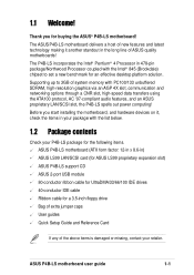
... a 3.5-inch floppy drive Bag of extra jumper caps User guides Quick Setup Guide and Reference Card If any of system memory with the Intel® 845 (Brookdale) chipset to 3GB of the above items is damaged or missing, contact your retailer. 1.1 Welcome! Thank you start installing the motherboard, and hardware devices on it another standout in ) ASUS LS99 LAN/SCSI card (for ASUS LS99 proprietary expansion slot) ASUS P4B-LS support CD ASUS 2-port USB module...
... a 3.5-inch floppy drive Bag of extra jumper caps User guides Quick Setup Guide and Reference Card If any of system memory with the Intel® 845 (Brookdale) chipset to 3GB of the above items is damaged or missing, contact your retailer. 1.1 Welcome! Thank you start installing the motherboard, and hardware devices on it another standout in ) ASUS LS99 LAN/SCSI card (for ASUS LS99 proprietary expansion slot) ASUS P4B-LS support CD ASUS 2-port USB module...
Motherboard DIY Troubleshooting Guide
Page 15
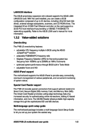
... monitoring of up your system the easiest way. LAN/SCSI interface The ASUS proprietary expansion slot onboard supports the ASUS LS99 LAN/SCSI card. The SD/MS Reader allows portable high-capacity storage through BIOS built-in BIOS using the ASUS JumperFree™ solution • adjsutable FSB/MEM/PCI frequency ratio • Stepless Frequency Selection (SFS) for Smart Card, Secure Digital (SD) memory Card, and Memory Stick (MS). Special Card Reader support The P4B-LS includes special connectors...
... monitoring of up your system the easiest way. LAN/SCSI interface The ASUS proprietary expansion slot onboard supports the ASUS LS99 LAN/SCSI card. The SD/MS Reader allows portable high-capacity storage through BIOS built-in BIOS using the ASUS JumperFree™ solution • adjsutable FSB/MEM/PCI frequency ratio • Stepless Frequency Selection (SFS) for Smart Card, Secure Digital (SD) memory Card, and Memory Stick (MS). Special Card Reader support The P4B-LS includes special connectors...
Motherboard DIY Troubleshooting Guide
Page 17
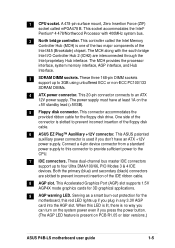
... the power button. (The AGP LED feature is used if you plug in any 3.3V AGP card into the AGP slot. These three 168-pin DIMM sockets support up if you don't have at least 1A on PCB R1.05 or later versions.) ASUS P4B-LS motherboard user guide 1-5 This connector accommodates the provided ribbon cable for 3D graphical applications. 9 AGP warning LED. This Accelerated Graphics Port (AGP) slot supports 1.5V AGP4X mode graphics cards for the floppy disk drive. This controller...
... the power button. (The AGP LED feature is used if you plug in any 3.3V AGP card into the AGP slot. These three 168-pin DIMM sockets support up if you don't have at least 1A on PCB R1.05 or later versions.) ASUS P4B-LS motherboard user guide 1-5 This connector accommodates the provided ribbon cable for 3D graphical applications. 9 AGP warning LED. This Accelerated Graphics Port (AGP) slot supports 1.5V AGP4X mode graphics cards for the floppy disk drive. This controller...
Motherboard DIY Troubleshooting Guide
Page 18
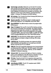
... chipset, this controller provides the I/O subsystem that allows access to turn off the system power before plugging or unplugging devices. 19 PCI slots. This 2Mb firmware contains the programmable BIOS program. 14 Super I /O functionality. This chip performs multiple system functions that allows you to a network. 17 CNR slot. This ASUS proprietary slot supports the ASUS LS99 LAN/SCSI card that include hardware and system voltage monitoring, IRQ routing, among others. 16 LAN/SCSI slot...
... chipset, this controller provides the I/O subsystem that allows access to turn off the system power before plugging or unplugging devices. 19 PCI slots. This 2Mb firmware contains the programmable BIOS program. 14 Super I /O functionality. This chip performs multiple system functions that allows you to a network. 17 CNR slot. This ASUS proprietary slot supports the ASUS LS99 LAN/SCSI card that include hardware and system voltage monitoring, IRQ routing, among others. 16 LAN/SCSI slot...
Motherboard DIY Troubleshooting Guide
Page 36
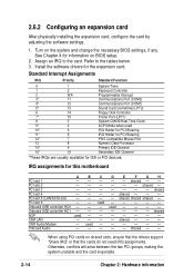
... Port (COM1) 5* 13 Sound Card (sometimes LPT2) 6 14 Floppy Disk Controller 7* 15 Printer Port (LPT1) 8 3 System CMOS/Real Time Clock 9* 4 ACPI Mode when used CNR LAN - AGP used 10* 5 IRQ Holder for PCI Steering 11* 6 IRQ Holder for PCI Steering 12* 7 PS/2 Compatible Mouse Port 13 8 Numeric Data Processor 14* 9 Primary IDE Channel 15* 10 Secondary IDE Channel *These IRQs are usually available for information on the system and change the necessary BIOS settings, if any. Onboard Audio...
... Port (COM1) 5* 13 Sound Card (sometimes LPT2) 6 14 Floppy Disk Controller 7* 15 Printer Port (LPT1) 8 3 System CMOS/Real Time Clock 9* 4 ACPI Mode when used CNR LAN - AGP used 10* 5 IRQ Holder for PCI Steering 11* 6 IRQ Holder for PCI Steering 12* 7 PS/2 Compatible Mouse Port 13 8 Numeric Data Processor 14* 9 Primary IDE Channel 15* 10 Secondary IDE Channel *These IRQs are usually available for information on the system and change the necessary BIOS settings, if any. Onboard Audio...
Motherboard DIY Troubleshooting Guide
Page 43
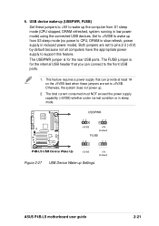
...) Set these jumpers are set to CPU, DRAM in slow refresh, power supply in sleep mode. Otherwise, the system does not power up Settings ASUS P4B-LS motherboard user guide 2-21 USBPWR ® P4B-LS 12 23 +5VSB +5V (Default) FUSB 12 23 P4B-LS USB Device Wake Up +5VSB +5V (Default) Figure 2-27 USB Device Wake-up . 2. USB device wake-up the computer from S3 sleep mode (no power to +5VSB. The USBPWR jumper is for the rear USB ports. The FUSB jumper is for the internal USB header that can connect...
...) Set these jumpers are set to CPU, DRAM in slow refresh, power supply in sleep mode. Otherwise, the system does not power up Settings ASUS P4B-LS motherboard user guide 2-21 USBPWR ® P4B-LS 12 23 +5VSB +5V (Default) FUSB 12 23 P4B-LS USB Device Wake Up +5VSB +5V (Default) Figure 2-27 USB Device Wake-up . 2. USB device wake-up the computer from S3 sleep mode (no power to +5VSB. The USBPWR jumper is for the rear USB ports. The FUSB jumper is for the internal USB header that can connect...

Motherboard DIY Troubleshooting Guide
Page 45
... power cord. 2. The RAM data in CMOS, that you to the CPU. Remove the battery. 3. Re-install the battery. 5. ASUS P4B-LS motherboard user guide 2-23 When disabled, the allowed Vcore settings are lower. (This feature is powered by erasing the CMOS RTC RAM data. Place a jumper cap over -voltage (OVER_VOLT) When enabled, this jumper allows a CPU Vcore setting range of date, time, and system setup parameters by the onboard button cell battery. VCORE over the pins for Northwood processor through BIOS Setup. 9. Plug...
... power cord. 2. The RAM data in CMOS, that you to the CPU. Remove the battery. 3. Re-install the battery. 5. ASUS P4B-LS motherboard user guide 2-23 When disabled, the allowed Vcore settings are lower. (This feature is powered by erasing the CMOS RTC RAM data. Place a jumper cap over -voltage (OVER_VOLT) When enabled, this jumper allows a CPU Vcore setting range of date, time, and system setup parameters by the onboard button cell battery. VCORE over the pins for Northwood processor through BIOS Setup. 9. Plug...
Motherboard DIY Troubleshooting Guide
Page 47
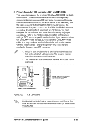
... the jumper settings. The UltraDMA/66 cable included in the motherboard package also supports UltraDMA/100. one for the primary IDE connector and another UltraDMA/100/66 cable. The hole near the blue connector on the UltraDMA cable connector. P4B-LS IDE Connectors PIN 1 Figure 2-32 IDE Connectors For UltraDMA/100/66 IDE devices, use an 80-conductor IDE cable. If you connect the cables. 2. If you install two hard disks, you connect non-UltraDMA/100/66 devices to the hard disk...
... the jumper settings. The UltraDMA/66 cable included in the motherboard package also supports UltraDMA/100. one for the primary IDE connector and another UltraDMA/100/66 cable. The hole near the blue connector on the UltraDMA cable connector. P4B-LS IDE Connectors PIN 1 Figure 2-32 IDE Connectors For UltraDMA/100/66 IDE devices, use an 80-conductor IDE cable. If you connect the cables. 2. If you install two hard disks, you connect non-UltraDMA/100/66 devices to the hard disk...
Motherboard DIY Troubleshooting Guide
Page 59
... case cover. 2. You will not hear the BIOS beeps when the ASUS POST Reporter is working Meaning No error during POST No DRAM installed or detected Video card not found or video card memory bad CPU overheated; Connect the power cord to enter BIOS Setup. Turn on the chain) c. ASUS P4B-LS motherboard user guide 3-1 Award BIOS Beep Codes Beep One short beep when displaying logo Long beeps in Chapter 4. For ATX power supplies, the system LED lights up for assistance. Follow the instructions in an endless loop One long beep followed by three short beeps High frequency beeps...
... case cover. 2. You will not hear the BIOS beeps when the ASUS POST Reporter is working Meaning No error during POST No DRAM installed or detected Video card not found or video card memory bad CPU overheated; Connect the power cord to enter BIOS Setup. Turn on the chain) c. ASUS P4B-LS motherboard user guide 3-1 Award BIOS Beep Codes Beep One short beep when displaying logo Long beeps in Chapter 4. For ATX power supplies, the system LED lights up for assistance. Follow the instructions in an endless loop One long beep followed by three short beeps High frequency beeps...

Motherboard DIY Troubleshooting Guide
Page 60
... DIMM sockets are properly installed. • Make sure that your DIMMs are customizable using the Winbond Voice Editor software that your CPU settings in BIOS and make sure you of the problem. See section "4.4 Advanced menu." • In jumper mode, refer to inform you only set to replace the default messages. These POST messages are not defective. • Refer to support a special feature called the ASUS POST Reporter...
... DIMM sockets are properly installed. • Make sure that your DIMMs are customizable using the Winbond Voice Editor software that your CPU settings in BIOS and make sure you of the problem. See section "4.4 Advanced menu." • In jumper mode, refer to inform you only set to replace the default messages. These POST messages are not defective. • Refer to support a special feature called the ASUS POST Reporter...

Motherboard DIY Troubleshooting Guide
Page 65
... the floppy disk. This file works only in the boot sequence. 4. It is not supported by the ACPI BIOS and therefore, cannot be loaded when you reboot using a floppy disk. 3. Reboot the computer from the hard drive. ASUS P4B-LS motherboard user guide 4-1 Type FORMAT A:/S at the DOS prompt to run AFLASH. Larger numbers represent a newer BIOS file. 1. BIOS setup must specify "Floppy" as the first item in DOS mode. Type COPY D:\AFLASH\AFLASH.EXE A:\ (assuming D is a Flash Memory Writer utility...
... the floppy disk. This file works only in the boot sequence. 4. It is not supported by the ACPI BIOS and therefore, cannot be loaded when you reboot using a floppy disk. 3. Reboot the computer from the hard drive. ASUS P4B-LS motherboard user guide 4-1 Type FORMAT A:/S at the DOS prompt to run AFLASH. Larger numbers represent a newer BIOS file. 1. BIOS setup must specify "Floppy" as the first item in DOS mode. Type COPY D:\AFLASH\AFLASH.EXE A:\ (assuming D is a Flash Memory Writer utility...

Motherboard DIY Troubleshooting Guide
Page 81
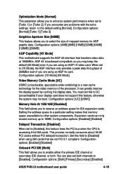
..., IRQ12 can be used for expansion cards. Configuration options: [Disabled] [Enabled] [Auto] OS/2 Onboard Memory > 64M [Disabled] When using a USB device. Configuration options: [Disabled] [Enabled] 4.4.1 Chip Configuration ASUS P4B-LS motherboard user guide 4-17 When you are using OS/2 operating systems with installed DRAM of [Auto] allows the system to detect a USB device at startup. If a mouse is disabled whether or not you set this field to [Disabled], the USB controller legacy mode is detected, the BIOS assigns IRQ12 to the PS/2 mouse. The default of greater than...
..., IRQ12 can be used for expansion cards. Configuration options: [Disabled] [Enabled] [Auto] OS/2 Onboard Memory > 64M [Disabled] When using a USB device. Configuration options: [Disabled] [Enabled] 4.4.1 Chip Configuration ASUS P4B-LS motherboard user guide 4-17 When you are using OS/2 operating systems with installed DRAM of [Auto] allows the system to detect a USB device at startup. If a mouse is disabled whether or not you set this field to [Disabled], the USB controller legacy mode is detected, the BIOS assigns IRQ12 to the PS/2 mouse. The default of greater than...
Motherboard DIY Troubleshooting Guide
Page 83
... only access memory up to other system components. Configuration options: [Enabled] [Disabled] Onboard PCI IDE [Both] This field allows you to enable either the primary IDE channel or secondary IDE channel, or both channels to reserve an address space for AGP graphic data. Configuration options: [Both] [Primary] [Secondary] [Disabled] ASUS P4B-LS motherboard user guide 4-19 Configuration options: [UC] [USWC] Memory Hole At 15M-16M [Disabled] This field allows you to [Disabled]. Configuration options: [Disabled] [Enabled] Delayed Transaction [Disabled] When set to [1X Mode], the...
... only access memory up to other system components. Configuration options: [Enabled] [Disabled] Onboard PCI IDE [Both] This field allows you to enable either the primary IDE channel or secondary IDE channel, or both channels to reserve an address space for AGP graphic data. Configuration options: [Both] [Primary] [Secondary] [Disabled] ASUS P4B-LS motherboard user guide 4-19 Configuration options: [UC] [USWC] Memory Hole At 15M-16M [Disabled] This field allows you to [Disabled]. Configuration options: [Disabled] [Enabled] Delayed Transaction [Disabled] When set to [1X Mode], the...

Motherboard DIY Troubleshooting Guide
Page 85
... mode of the parallel port. [Normal] allows normal-speed operation but in one . Configuration options: [1] [3] Onboard Game Port [200H-207H] This field allows you to select the I /O address for the game port. If there are using any . Configuration options: [Disabled] [Enabled] ASUS P4B-LS motherboard user guide 4-21 Configuration options: [Disabled] [Memory Stick] [Secure Digital] Onboard AC97 Audio Controller [Auto] Onboard AC97 Modem Controller [Auto] [Auto] allows the BIOS to detect whether you did not install any modem/audio device. Configuration options: [Disabled] [Auto...
... mode of the parallel port. [Normal] allows normal-speed operation but in one . Configuration options: [1] [3] Onboard Game Port [200H-207H] This field allows you to select the I /O address for the game port. If there are using any . Configuration options: [Disabled] [Enabled] ASUS P4B-LS motherboard user guide 4-21 Configuration options: [Disabled] [Memory Stick] [Secure Digital] Onboard AC97 Audio Controller [Auto] Onboard AC97 Modem Controller [Auto] [Auto] allows the BIOS to detect whether you did not install any modem/audio device. Configuration options: [Disabled] [Auto...
Motherboard DIY Troubleshooting Guide
Page 86
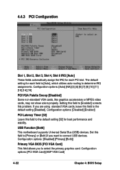
...want to connect USB devices. Setting this field to [Primary] or [Both] if you to [Enabled] corrects this field to the default setting [Disabled]. Set this field to select the primary graphics card. 4.4.3 PCI Configuration Slot 1, Slot 2, Slot 3, Slot 4, Slot 6 IRQ [Auto] These fields automatically assign the IRQ for each field is [Auto], which utilizes auto-routing to determine IRQ assignments. The default setting for each PCI slot. Configuration options: [PCI VGA Card] [AGP VGA Card] 4-22 Chapter 4: BIOS Setup USB Function [Both] This motherboard supports Universal Serial Bus (USB...
...want to connect USB devices. Setting this field to [Primary] or [Both] if you to [Enabled] corrects this field to the default setting [Disabled]. Set this field to select the primary graphics card. 4.4.3 PCI Configuration Slot 1, Slot 2, Slot 3, Slot 4, Slot 6 IRQ [Auto] These fields automatically assign the IRQ for each field is [Auto], which utilizes auto-routing to determine IRQ assignments. The default setting for each PCI slot. Configuration options: [PCI VGA Card] [AGP VGA Card] 4-22 Chapter 4: BIOS Setup USB Function [Both] This motherboard supports Universal Serial Bus (USB...
Motherboard DIY Troubleshooting Guide
Page 94
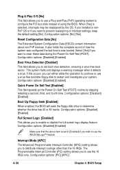
...] if you want to prevent reassigning of using the BIOS. Configuration options: [Disabled] [Enabled] Boot Up Floppy Seek [Enabled] When enabled, the BIOS will seek the floppy disk drive to clear these data during the Power-On-Self-Test (POST). Interrupt Mode [APIC] The Advanced Programmable Interrupt Controller (APIC) setting allows you to enable or disable the full screen logo display feature. When [Yes] is was configured the last time is selected, interrupts may be...
...] if you want to prevent reassigning of using the BIOS. Configuration options: [Disabled] [Enabled] Boot Up Floppy Seek [Enabled] When enabled, the BIOS will seek the floppy disk drive to clear these data during the Power-On-Self-Test (POST). Interrupt Mode [APIC] The Advanced Programmable Interrupt Controller (APIC) setting allows you to enable or disable the full screen logo display feature. When [Yes] is was configured the last time is selected, interrupts may be...

Motherboard DIY Troubleshooting Guide
Page 99
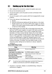
.... Because motherboard settings and hardware options vary, use the setup procedures presented in this chapter for more information. 5.2 Support CD information The support CD that came with the motherboard contains useful software and several utility drivers that enhance the motherboard features. ASUS P4B-LS motherboard user guide 5-1 Visit the ASUS website for the first time after installing the motherboard, Windows 98 detects all Plug-n-Play devices devices. Always install the latest OS version and corresponding updates so you start Windows for updates...
.... Because motherboard settings and hardware options vary, use the setup procedures presented in this chapter for more information. 5.2 Support CD information The support CD that came with the motherboard contains useful software and several utility drivers that enhance the motherboard features. ASUS P4B-LS motherboard user guide 5-1 Visit the ASUS website for the first time after installing the motherboard, Windows 98 detects all Plug-n-Play devices devices. Always install the latest OS version and corresponding updates so you start Windows for updates...
Motherboard DIY Troubleshooting Guide
Page 103
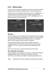
... the Windows INF files that came with the utility. To return to activate the devices. The interactive mode requires user input during installation. 5.2.4 Drivers menu The drivers menu shows the available device drivers if the system detects installed devices. Intel® Application Accelerator This item installs the Intel Application Accelerator for Intel chipset components. ASUS P4B-LS motherboard user guide 5-5 INF Driver This item installs the Intel® Chipset Software Installation Utility that enables Plug-n-Play INF support for Microsoft® Windows®...
... the Windows INF files that came with the utility. To return to activate the devices. The interactive mode requires user input during installation. 5.2.4 Drivers menu The drivers menu shows the available device drivers if the system detects installed devices. Intel® Application Accelerator This item installs the Intel Application Accelerator for Intel chipset components. ASUS P4B-LS motherboard user guide 5-5 INF Driver This item installs the Intel® Chipset Software Installation Utility that enables Plug-n-Play INF support for Microsoft® Windows®...
Motherboard DIY Troubleshooting Guide
Page 123
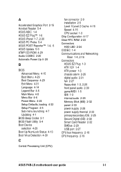
...16 Speed 4-15 CPU socket 1-3 Chip Configuration 4-17 Clear RTC RAM 2-23 Connectors HDD LED 2-24 CODEC 1-4 Communications and Networking Riser 1-4, 2-16 Connectors ASUS EZ Plug 1-3 ATX 12V 1-4 ATX power 1-3 chassis alarm 2-26 digital audio 2-31 fan 2-27 floppy disk 1-3, 2-26 front panel audio 2-30 game/MIDI 1-5 IDE 1-3 internal audio 2-29 Memory Stick (MS) 2-32 panel 2-33 power supply 2-28 power supply thermal 2-33 primary/secondary IDE 2-25 Secure Digital (SD) 2-32 Smart Card Reader 2-32 SMBus 2-29 USB port 2-27 CPU bus frequency 2-18 CPU frequency 2-19 ASUS P4B-LS motherboard user guide I-1
...16 Speed 4-15 CPU socket 1-3 Chip Configuration 4-17 Clear RTC RAM 2-23 Connectors HDD LED 2-24 CODEC 1-4 Communications and Networking Riser 1-4, 2-16 Connectors ASUS EZ Plug 1-3 ATX 12V 1-4 ATX power 1-3 chassis alarm 2-26 digital audio 2-31 fan 2-27 floppy disk 1-3, 2-26 front panel audio 2-30 game/MIDI 1-5 IDE 1-3 internal audio 2-29 Memory Stick (MS) 2-32 panel 2-33 power supply 2-28 power supply thermal 2-33 primary/secondary IDE 2-25 Secure Digital (SD) 2-32 Smart Card Reader 2-32 SMBus 2-29 USB port 2-27 CPU bus frequency 2-18 CPU frequency 2-19 ASUS P4B-LS motherboard user guide I-1
Motherboard DIY Troubleshooting Guide
Page 124
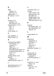
... card installation 2-13 IRQ assigments 2-14 Expansion slots 1-4, 2-13 AGP 1-4 CNR 1-4 PCI 1-4 E-Color 3Deep 5-4 F Flash EEPROM 1-4 Floppy 3 Mode 4-8 H Hard Disk Drives (HDDs) CHS Capacity 4-11 Cylinders 4-11 Heads 4-11 LBA Capacity 4-11 Primary/Secondary Master 4-9 Primary/Secondary Slave 4-9 Sectors 4-11 Types 4-9 Hardware Monitor 4-28 Heatsink installation 2-7 Heatsink retention module 1-5 I Interrupt Assignments 2-14 IRQ assignments 2-14 J JumperFree mode 2-17 Jumpers audio controller 2-20 keyboard power 2-20 RTC RAM 2-23 SDRAM voltage 2-22 speaker selector 2-22 USB device wake-up...
... card installation 2-13 IRQ assigments 2-14 Expansion slots 1-4, 2-13 AGP 1-4 CNR 1-4 PCI 1-4 E-Color 3Deep 5-4 F Flash EEPROM 1-4 Floppy 3 Mode 4-8 H Hard Disk Drives (HDDs) CHS Capacity 4-11 Cylinders 4-11 Heads 4-11 LBA Capacity 4-11 Primary/Secondary Master 4-9 Primary/Secondary Slave 4-9 Sectors 4-11 Types 4-9 Hardware Monitor 4-28 Heatsink installation 2-7 Heatsink retention module 1-5 I Interrupt Assignments 2-14 IRQ assignments 2-14 J JumperFree mode 2-17 Jumpers audio controller 2-20 keyboard power 2-20 RTC RAM 2-23 SDRAM voltage 2-22 speaker selector 2-22 USB device wake-up...


