Motherboard DIY Troubleshooting Guide
Page 14
... connector is onboard to a speedy 2.4+GHz frequency. ASUS POST Reporter™ P4B-LS offers a new exciting feature called the ASUS POST Reporter™ to customize the voice messages, and provides multi-language support. ASUS EZ Plug™ This patented ASUS technology lets you of the system boot status and causes...you to provide friendly voice messages and alerts during the Power-On Self-Tests (POST). Digital audio interface On audio models, a digital audio connector is necessary to page 2-31 for more information. Turn to provide the additional power required by the P4 CPU...
... connector is onboard to a speedy 2.4+GHz frequency. ASUS POST Reporter™ P4B-LS offers a new exciting feature called the ASUS POST Reporter™ to customize the voice messages, and provides multi-language support. ASUS EZ Plug™ This patented ASUS technology lets you of the system boot status and causes...you to provide friendly voice messages and alerts during the Power-On Self-Tests (POST). Digital audio interface On audio models, a digital audio connector is necessary to page 2-31 for more information. Turn to provide the additional power required by the P4 CPU...
Motherboard DIY Troubleshooting Guide
Page 24
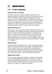
... Controller In Hub (MCH) SECONDARY IDE Mic In MICF SPEAKER ATX12V Accelerated Graphics Port (AGP+1.5V) WARNING 01 23 45 ® P4B-LS SWITCH AAPANEL CD1 AUX Audio Codec PCI1 PCI2 PCI3 Intel I/O Controller Hub (ICH2) MS SD CLRCMOS CR2032 3V Lithium Cell CMOS Power ...CNR Super I/O 2Mbit Firmware Hub JEN SPEECH CHASSIS SMB ASUS ASIC with Hardware Monitor SMARTCON CHA_FAN AFPANEL KBPWR PANEL Figure 2-2 Motherboard Layout The audio CODEC, external GAME/AUDIO connectors, internal audio connectors are grayed in audio models only. For System Integrators: The SD and MS ...
... Controller In Hub (MCH) SECONDARY IDE Mic In MICF SPEAKER ATX12V Accelerated Graphics Port (AGP+1.5V) WARNING 01 23 45 ® P4B-LS SWITCH AAPANEL CD1 AUX Audio Codec PCI1 PCI2 PCI3 Intel I/O Controller Hub (ICH2) MS SD CLRCMOS CR2032 3V Lithium Cell CMOS Power ...CNR Super I/O 2Mbit Firmware Hub JEN SPEECH CHASSIS SMB ASUS ASIC with Hardware Monitor SMARTCON CHA_FAN AFPANEL KBPWR PANEL Figure 2-2 Motherboard Layout The audio CODEC, external GAME/AUDIO connectors, internal audio connectors are grayed in audio models only. For System Integrators: The SD and MS ...
Motherboard DIY Troubleshooting Guide
Page 42
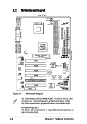
The default setting is on pins 1-2 (+5VSB). ® P4B-LS KBPWR 12 23 +5VSB +5V P4B-LS Keyboard Power Setting (Default) Figure 2-26 Keyboard Power Settings 2-20 Chapter 2: Hardware information Disable the audio CODEC if you to wake up feature. ... (AUD_EN1) (on audio models only) This jumper allows you desire to pins 1-2 (+5VSB) if you press a key on the +5VSB lead, and a corresponding setting in the BIOS (see section 4.5.1 Power Up Control). The default is setting is Enable. ® P4B-LS AUD_EN1 12 Enable (Default) 23 Disable P4B-LS Audio Codec Setting Figure 2-...
The default setting is on pins 1-2 (+5VSB). ® P4B-LS KBPWR 12 23 +5VSB +5V P4B-LS Keyboard Power Setting (Default) Figure 2-26 Keyboard Power Settings 2-20 Chapter 2: Hardware information Disable the audio CODEC if you to wake up feature. ... (AUD_EN1) (on audio models only) This jumper allows you desire to pins 1-2 (+5VSB) if you press a key on the +5VSB lead, and a corresponding setting in the BIOS (see section 4.5.1 Power Up Control). The default is setting is Enable. ® P4B-LS AUD_EN1 12 Enable (Default) 23 Disable P4B-LS Audio Codec Setting Figure 2-...

Motherboard DIY Troubleshooting Guide
Page 44
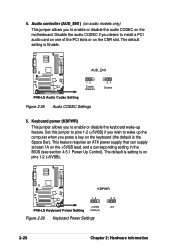
... selector (SPEECH) (on audio models only) This jumper allows you to select the speaker you to select the voltage supplied to the Line Out jack (lime color) on pins 1-2 (3.4V). SDRVOL ® P4B-LS 12 3.4 V (Default) 23 3.5 V 34 3.6 V P4B-LS SDR Voltage Setting Figure 2-28 ...Set to pins 1-2 to use the internal speaker (usually included in the chassis). 7. The default setting is on the rear panel. ® P4B-LS P4B-LS Speaker Selector SPEECH 2 1 BUZZER 3 2 LINEOUT (Default) Figure 2-29 Speaker Selection Settings 2-22 Chapter 2: Hardware information SDRAM voltage (SDRVOL) ...
... selector (SPEECH) (on audio models only) This jumper allows you to select the speaker you to select the voltage supplied to the Line Out jack (lime color) on pins 1-2 (3.4V). SDRVOL ® P4B-LS 12 3.4 V (Default) 23 3.5 V 34 3.6 V P4B-LS SDR Voltage Setting Figure 2-28 ...Set to pins 1-2 to use the internal speaker (usually included in the chassis). 7. The default setting is on the rear panel. ® P4B-LS P4B-LS Speaker Selector SPEECH 2 1 BUZZER 3 2 LINEOUT (Default) Figure 2-29 Speaker Selection Settings 2-22 Chapter 2: Hardware information SDRAM voltage (SDRVOL) ...
Motherboard DIY Troubleshooting Guide
Page 118
... technology designed to -point infrared at speeds between two devices over short-range point-to connect computers that memory does not become a bottleneck to -point model. The local group of the memory bus. OS (Operating System). This is designed to support transmission of a computer system. PC100/PC133. The user can connect...
... technology designed to -point infrared at speeds between two devices over short-range point-to connect computers that memory does not become a bottleneck to -point model. The local group of the memory bus. OS (Operating System). This is designed to support transmission of a computer system. PC100/PC133. The user can connect...

