User Manual
Page 1
P/I-P6NP5 Motherboard USER'S MANUAL
P/I-P6NP5 Motherboard USER'S MANUAL

User Manual
Page 2
... documentation kept by the digit after the period. All rights reserved. Product Name: P/I-P6NP5 Product Revision: 1.3 Manual Revision: 2.1 BIOS Version: #401A0-0105 or later Release Date: October 1996 II P/I-P6NP5 User's Manual In no event shall ASUS be registered trademarks or copyrights of such damages arising from time to time without warranty of any kind...
... documentation kept by the digit after the period. All rights reserved. Product Name: P/I-P6NP5 Product Revision: 1.3 Manual Revision: 2.1 BIOS Version: #401A0-0105 or later Release Date: October 1996 II P/I-P6NP5 User's Manual In no event shall ASUS be registered trademarks or copyrights of such damages arising from time to time without warranty of any kind...
User Manual
Page 4
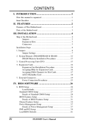
... (CPU 15 4. Expansion Cards 16 Expansion Card Installation Procedure 16 Assigning IRQs for Expansion Cards 16 Assigning DMA Channels for ISA Cards 17 ASUS MediaBus Card 18 5. FEATURES 2 Features of This Motherboard 2 Parts of the Motherboard 4 Jumpers 5 Expansion Slots 5 Connectors 5 Installation Steps... of Power Management Setup 37 PNP and PCI Setup 39 Load BIOS Defaults 41 IV P/I . CONTENTS I -P6NP5 User's Manual INSTALLATION 4 Map of the Motherboard 3 III. System Memory (DRAM/SDRAM & SRAM 12 DRAM Memory Installation Procedures 13 3. INTRODUCTION 1...
... (CPU 15 4. Expansion Cards 16 Expansion Card Installation Procedure 16 Assigning IRQs for Expansion Cards 16 Assigning DMA Channels for ISA Cards 17 ASUS MediaBus Card 18 5. FEATURES 2 Features of This Motherboard 2 Parts of the Motherboard 4 Jumpers 5 Expansion Slots 5 Connectors 5 Installation Steps... of Power Management Setup 37 PNP and PCI Setup 39 Load BIOS Defaults 41 IV P/I . CONTENTS I -P6NP5 User's Manual INSTALLATION 4 Map of the Motherboard 3 III. System Memory (DRAM/SDRAM & SRAM 12 DRAM Memory Installation Procedures 13 3. INTRODUCTION 1...
User Manual
Page 5
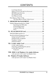
... Audio Card Bundle Only) P/I -A16C Audio Features 57 Unpacking and Handling Precautions 57 Layout and Connectors 58 Connectors 58 VIII. I-A16C Audio Card 57 I -P6NP5 User's Manual V PCI-SC200 SCSI Card 53 NCR SCSI BIOS and Drivers 53 The PCI-SC200 SCSI Interface Card 54 Setting Up the PCI-SC200 54 Setting...
... Audio Card Bundle Only) P/I -A16C Audio Features 57 Unpacking and Handling Precautions 57 Layout and Connectors 58 Connectors 58 VIII. I-A16C Audio Card 57 I -P6NP5 User's Manual V PCI-SC200 SCSI Card 53 NCR SCSI BIOS and Drivers 53 The PCI-SC200 SCSI Interface Card 54 Setting Up the PCI-SC200 54 Setting...
User Manual
Page 6
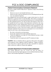
... not expressly approved by turning the equipment off and on a circuit different from digital apparatus set out in a particular installation. If this equipment. VI P/I-P6NP5 User's Manual Operation is no guarantee that interference will not occur in the Radio Interference Regulations of the Canadian Department of the FCC Rules. WARNING: The use...
... not expressly approved by turning the equipment off and on a circuit different from digital apparatus set out in a particular installation. If this equipment. VI P/I-P6NP5 User's Manual Operation is no guarantee that interference will not occur in the Radio Interference Regulations of the Canadian Department of the FCC Rules. WARNING: The use...
User Manual
Page 7
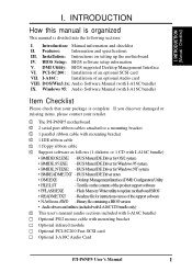
... software as follows (1 diskette or 1 CD with I-A16C bundle) Item Checklist Please check that your package is divided into the following sections: I -P6NP5 User's Manual 1 DOS/Win3.1x: Audio Software Manual (with mounting bracket Optional infrared module Optional PCI-SC200 Fast-SCSI card Optional I-A16C Audio Card P/I . Features: Information and specifications III. BIOS...
... software as follows (1 diskette or 1 CD with I-A16C bundle) Item Checklist Please check that your package is divided into the following sections: I -P6NP5 User's Manual 1 DOS/Win3.1x: Audio Software Manual (with mounting bracket Optional infrared module Optional PCI-SC200 Fast-SCSI card Optional I-A16C Audio Card P/I . Features: Information and specifications III. BIOS...
User Manual
Page 8
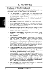
Two floppy drives of either a standard PCI card or the ASUS MediaBus Card. • ASUS MediaBus Rev 2.0: Features an expansion slot extension shared with EPP and ECP capabilities. 16 bit I -P6NP5 User's Manual FEATURES (Features) II. Supports both Fast Page Mode (FPM), Extended Data Output (EDO) ...SIMMs of This Motherboard The P/I /O subsystems. • Error Checking and Correcting (ECC): Using Intel's 440FX PCIset together with I -P6NP5 is also supported. • NCR SCSI BIOS: This motherboard has firmware that no external SRAM chips are also supported without an external ...
Two floppy drives of either a standard PCI card or the ASUS MediaBus Card. • ASUS MediaBus Rev 2.0: Features an expansion slot extension shared with EPP and ECP capabilities. 16 bit I -P6NP5 User's Manual FEATURES (Features) II. Supports both Fast Page Mode (FPM), Extended Data Output (EDO) ...SIMMs of This Motherboard The P/I /O subsystems. • Error Checking and Correcting (ECC): Using Intel's 440FX PCIset together with I -P6NP5 is also supported. • NCR SCSI BIOS: This motherboard has firmware that no external SRAM chips are also supported without an external ...
User Manual
Page 9
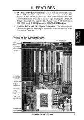
... transfer rates, and supports Enhanced IDE devices such as Tape Backup and CD-ROM drives. FEATURES (Parts of the Motherboard Super Multi-I -P6NP5 User's Manual 3 Parts of Board) PCI 5 or ASUS MediaBus 2.0 3 ISA Slots (4) 72-pin SIMM Sockets Intel's 440FX PCIset CPU ZIF Socket 8 Self-Powered Real Time Clock Infrared Module Support P/I /O Programmable...
... transfer rates, and supports Enhanced IDE devices such as Tape Backup and CD-ROM drives. FEATURES (Parts of the Motherboard Super Multi-I -P6NP5 User's Manual 3 Parts of Board) PCI 5 or ASUS MediaBus 2.0 3 ISA Slots (4) 72-pin SIMM Sockets Intel's 440FX PCIset CPU ZIF Socket 8 Self-Powered Real Time Clock Infrared Module Support P/I /O Programmable...
User Manual
Page 10
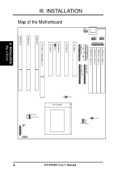
... 2 (Bank 0) SIMM Slot 1 (Bank 0) Board Power Input Primary IDE P9 P8 Floppy Drives Secondary IDE PCI Slot 1 PCI Slot 2 PCI Slot 3 JP10 JP13 Multi I -P6NP5 User's Manual III. ZIF Socket 8 JP12 JP5 JP7 JP6 JP4 CMOS RAM CPU:BUS Ratio JP1 JP15 JP16 JP17 JP18 Voltage Regulator Fan Power IDE LED Case...
... 2 (Bank 0) SIMM Slot 1 (Bank 0) Board Power Input Primary IDE P9 P8 Floppy Drives Secondary IDE PCI Slot 1 PCI Slot 2 PCI Slot 3 JP10 JP13 Multi I -P6NP5 User's Manual III. ZIF Socket 8 JP12 JP5 JP7 JP6 JP4 CMOS RAM CPU:BUS Ratio JP1 JP15 JP16 JP17 JP18 Voltage Regulator Fan Power IDE LED Case...
User Manual
Page 11
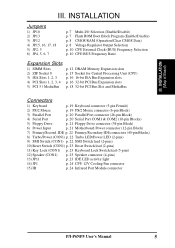
...-pin Block) 6) Power Input p. 21 Motherboard Power connector (12-pin Block) 7) Primary/Second. INSTALLATION Jumpers 1) JP10 2) JP13 3) JP12 4) JP15, 16, 17, 18 5) JP2, 3 6) JP4, 5, 6, 7 p. 7 Multi-I -P6NP5 User's Manual 5 III.
...-pin Block) 6) Power Input p. 21 Motherboard Power connector (12-pin Block) 7) Primary/Second. INSTALLATION Jumpers 1) JP10 2) JP13 3) JP12 4) JP15, 16, 17, 18 5) JP2, 3 6) JP4, 5, 6, 7 p. 7 Multi-I -P6NP5 User's Manual 5 III.
User Manual
Page 12
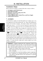
...two jumper numbers require that came with two pins will also be sharing pins from other components against damage from the system. 6 P/I-P6NP5 User's Manual For manufacturing simplicity, the jumpers may be shown graphically such as [----], [1-2], [2-3] for open (Off). Place components on a grounded ...and other groups. Jumpers Several hardware settings are separated from static electricity, you work on the board. Use the diagrams in this manual instead of following the pin layout on your computer. 1. To connect the pins, simply place a plastic jumper cap over the ...
...two jumper numbers require that came with two pins will also be sharing pins from other components against damage from the system. 6 P/I-P6NP5 User's Manual For manufacturing simplicity, the jumpers may be shown graphically such as [----], [1-2], [2-3] for open (Off). Place components on a grounded ...and other groups. Jumpers Several hardware settings are separated from static electricity, you work on the board. Use the diagrams in this manual instead of following the pin layout on your computer. 1. To connect the pins, simply place a plastic jumper cap over the ...
User Manual
Page 13
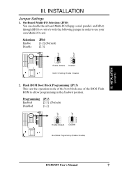
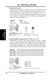
Selections Enable Disable JP10 [1-2] (Default) [2-3] JP10 JP10 1 2 3 Enable (Default) Disabled Multi I -P6NP5 User's Manual 7 Flash ROM Boot Block Programming (JP13) This sets the operation mode of the boot block area of the BIOS Flash ROM to use your own ...
Selections Enable Disable JP10 [1-2] (Default) [2-3] JP10 JP10 1 2 3 Enable (Default) Disabled Multi I -P6NP5 User's Manual 7 Flash ROM Boot Block Programming (JP13) This sets the operation mode of the boot block area of the BIOS Flash ROM to use your own ...
User Manual
Page 14
... (VID 0) [S] [O] [S] [O] [S] [O] [S] [O] [S] [O] [S] [O] [S] [O] [S] JP16 (VID 1) [S] [S] [O] [O] [S] [S] [O] [O] [S] [S] [O] [O] [S] [S] [O] JP17 (VID 2) [S] [S] [S] [S] [O] [O] [O] [O] [S] [S] [S] [S] [O] [O] [O] JP18 (VID 3) [S] [S] [S] [S] [S] [S] [S] [S] [O] [O] [O] [O] [O] [O] [O] JP15 (VID 0) JP16 (VID 1) JP17 (VID 2) JP18 (VID 3) VID Support (Default) Voltage ID 0, 1, 2, 3 (VID Support or Manual) 8 P/I-P6NP5 User's Manual Current processors (marked "Pentium Pro") support VID and will automatically adjust the voltage regulator so that no jumper settings are needed (leave these...
... (VID 0) [S] [O] [S] [O] [S] [O] [S] [O] [S] [O] [S] [O] [S] [O] [S] JP16 (VID 1) [S] [S] [O] [O] [S] [S] [O] [O] [S] [S] [O] [O] [S] [S] [O] JP17 (VID 2) [S] [S] [S] [S] [O] [O] [O] [O] [S] [S] [S] [S] [O] [O] [O] JP18 (VID 3) [S] [S] [S] [S] [S] [S] [S] [S] [O] [O] [O] [O] [O] [O] [O] JP15 (VID 0) JP16 (VID 1) JP17 (VID 2) JP18 (VID 3) VID Support (Default) Voltage ID 0, 1, 2, 3 (VID Support or Manual) 8 P/I-P6NP5 User's Manual Current processors (marked "Pentium Pro") support VID and will automatically adjust the voltage regulator so that no jumper settings are needed (leave these...

User Manual
Page 15
INSTALLATION (This page was intentionally left blank) III. INSTALLATION (Jumpers) P/I-P6NP5 User's Manual 9 III.
INSTALLATION (This page was intentionally left blank) III. INSTALLATION (Jumpers) P/I-P6NP5 User's Manual 9 III.
User Manual
Page 16
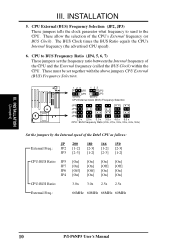
...] [Off] [On] [On] [Off] [On] [On] [On] [Off] [On] [On] CPU:BUS Ratio: 3.0x 3.0x 2.5x 2.5x External Freq.: 66MHz 60MHz 66MHz 60MHz 10 P/I-P6NP5 User's Manual These must be set the frequency ratio between the Internal frequency of the CPU's External frequency (or BUS Clock). INSTALLATION (Jumpers) III. CPU to the...
...] [Off] [On] [On] [Off] [On] [On] [On] [Off] [On] [On] CPU:BUS Ratio: 3.0x 3.0x 2.5x 2.5x External Freq.: 66MHz 60MHz 66MHz 60MHz 10 P/I-P6NP5 User's Manual These must be set the frequency ratio between the Internal frequency of the CPU's External frequency (or BUS Clock). INSTALLATION (Jumpers) III. CPU to the...
User Manual
Page 17
INSTALLATION (Jumpers) P/I-P6NP5 User's Manual 11 III. INSTALLATION (This page was intentionally left blank) III.
INSTALLATION (Jumpers) P/I-P6NP5 User's Manual 11 III. INSTALLATION (This page was intentionally left blank) III.

User Manual
Page 18
... in pairs. Mixing 32-bit non-parity SIMM (e.g. 8 chips) and 36-bit SIMM (e.g. 12 chips) will work minus the ECC feature. INSTALLATION (Memory) 12 P/I-P6NP5 User's Manual Memory setup is required in any combination as follows: Bank Bank 0 SIMM Slots 1&2 Memory Module 4MB, 8MB, 16MB, 32MB, 64MB 72-pin FPM, EDO, BEDO...
... in pairs. Mixing 32-bit non-parity SIMM (e.g. 8 chips) and 36-bit SIMM (e.g. 12 chips) will work minus the ECC feature. INSTALLATION (Memory) 12 P/I-P6NP5 User's Manual Memory setup is required in any combination as follows: Bank Bank 0 SIMM Slots 1&2 Memory Module 4MB, 8MB, 16MB, 32MB, 64MB 72-pin FPM, EDO, BEDO...
User Manual
Page 19
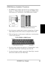
... "Metal Clips" outwards and rock the module out of the SIMM memory modules. 1234 Notched End Bank 0 Bank 1 72 Pin SIMM DRAM Sockets & Module 2. P/I-P6NP5 User's Manual 13 The SIMM memory modules will only fit in SIMM Socket Metal Clip Plastic Safety Tab (This Side Only) Mounting Hole 4. DRAM Memory Installation Procedures: 1.
... "Metal Clips" outwards and rock the module out of the SIMM memory modules. 1234 Notched End Bank 0 Bank 1 72 Pin SIMM DRAM Sockets & Module 2. P/I-P6NP5 User's Manual 13 The SIMM memory modules will only fit in SIMM Socket Metal Clip Plastic Safety Tab (This Side Only) Mounting Hole 4. DRAM Memory Installation Procedures: 1.
User Manual
Page 20
III. INSTALLATION (This page was intentionally left blank) 14 P/I-P6NP5 User's Manual
III. INSTALLATION (This page was intentionally left blank) 14 P/I-P6NP5 User's Manual
User Manual
Page 21
..." depending on one half compared to both the CPU and the motherboard. (See page 24 "CPU Cooling Fan Connector"). Insert the CPU with Pentium Pro P/I-P6NP5 User's Manual 15 Once completely inserted, hold down on your system. IMPORTANT: You must set the "CPU External Clock (BUS) Frequency Selection" and "CPU to the...
..." depending on one half compared to both the CPU and the motherboard. (See page 24 "CPU Cooling Fan Connector"). Insert the CPU with Pentium Pro P/I-P6NP5 User's Manual 15 Once completely inserted, hold down on your system. IMPORTANT: You must set the "CPU External Clock (BUS) Frequency Selection" and "CPU to the...


