User Manual
Page 3
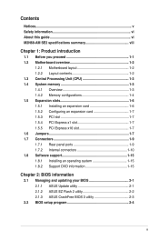
... (CPU 1-3 1.4 System memory 1-3 1.4.1 Overview 1-3 1.4.2 Memory configurations 1-4 1.5 Expansion slots 1-6 1.5.1 Installing an expansion card 1-6 1.5.2 Configuring an expansion card 1-7 1.5.3 PCI slot 1-7 1.5.4 PCI Express x1 slot 1-7 1.5.5 PCI Express x16 slot 1-7 1.6 Jumpers 1-7 1.7 Connectors 1-9 1.7.1 Rear panel ports 1-9 1.7.2 Internal connectors 1-10 1.8 Software support 1-15 1.8.1 Installing an operating system 1-15 1.8.2 Support DVD information 1-15 Chapter 2: BIOS information 2.1 Managing and updating your BIOS 2-1 2.1.1 ASUS Update utility 2-1 2.1.2 ASUS EZ Flash...
... (CPU 1-3 1.4 System memory 1-3 1.4.1 Overview 1-3 1.4.2 Memory configurations 1-4 1.5 Expansion slots 1-6 1.5.1 Installing an expansion card 1-6 1.5.2 Configuring an expansion card 1-7 1.5.3 PCI slot 1-7 1.5.4 PCI Express x1 slot 1-7 1.5.5 PCI Express x16 slot 1-7 1.6 Jumpers 1-7 1.7 Connectors 1-9 1.7.1 Rear panel ports 1-9 1.7.2 Internal connectors 1-10 1.8 Software support 1-15 1.8.1 Installing an operating system 1-15 1.8.2 Support DVD information 1-15 Chapter 2: BIOS information 2.1 Managing and updating your BIOS 2-1 2.1.1 ASUS Update utility 2-1 2.1.2 ASUS EZ Flash...
User Manual
Page 8
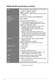
.../667MHz memory modules Supports up to 10 USB 2.0/1.1 ports (6 ports at mid-board, 4 ports at the back panel) Realtek RTL8201CP Phy 10/100 LAN (continued on the next page) viii Integrated programmable Shader model 3.0 DirectX 9 graphics processor Maximum shared memory of 4GB or more, Windows® 32-bit operating system may only recognize less than 3GB is supported by AM2+ CPU only. M2N68-AM SE2 specifications summary CPU Chipset System bus Memory Graphics Expansion slots Storage Audio USB LAN AMD® Socket...
.../667MHz memory modules Supports up to 10 USB 2.0/1.1 ports (6 ports at mid-board, 4 ports at the back panel) Realtek RTL8201CP Phy 10/100 LAN (continued on the next page) viii Integrated programmable Shader model 3.0 DirectX 9 graphics processor Maximum shared memory of 4GB or more, Windows® 32-bit operating system may only recognize less than 3GB is supported by AM2+ CPU only. M2N68-AM SE2 specifications summary CPU Chipset System bus Memory Graphics Expansion slots Storage Audio USB LAN AMD® Socket...
User Manual
Page 11
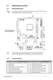
...Front panel audio connector (10-1 pin AAFP) 16. Keyboard/mouse power (3-pin PS2_USBPW 1-4) 5. USB device wake-up (3-pin USBPW 5-10) Page 1-13 1-3 1-3 1-9 1-11 1-12 1-10 1-8 Connectors/Jumpers/Slots/LED 9. Clear RTC RAM (3-pin CLRTC) 11. Place this side towards the rear of the chassis. 1.2 1.2.1 Motherboard overview Motherboard layout Ensure that you install the motherboard into the holes indicated by circles to secure the motherboard to the rear part of the chassis. AM2 CPU Socket 3. DDR2 DIMM slots 4. Serial ATA connectors (7-pin SATA1, SATA2) 8. Internal speaker connector...
...Front panel audio connector (10-1 pin AAFP) 16. Keyboard/mouse power (3-pin PS2_USBPW 1-4) 5. USB device wake-up (3-pin USBPW 5-10) Page 1-13 1-3 1-3 1-9 1-11 1-12 1-10 1-8 Connectors/Jumpers/Slots/LED 9. Clear RTC RAM (3-pin CLRTC) 11. Place this side towards the rear of the chassis. 1.2 1.2.1 Motherboard overview Motherboard layout Ensure that you install the motherboard into the holes indicated by circles to secure the motherboard to the rear part of the chassis. AM2 CPU Socket 3. DDR2 DIMM slots 4. Serial ATA connectors (7-pin SATA1, SATA2) 8. Internal speaker connector...
User Manual
Page 13
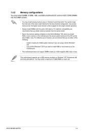
Use a 64-bit Windows® OS if you do either of the following: - This motherboard supports up of 256 megabits (Mb) chips or less. ASUS M2N68-AM SE2 1-4 For effective use of memory, we recommend that you want to 4GB memory modules on the motherboard, the actual usable memory for the dual-channel configuration. 1.4.2 Memory configurations You may install 256MB, 512MB, 1GB, and 2GB unbuffered ECC and non-ECC DDR2 DIMMs...
Use a 64-bit Windows® OS if you do either of the following: - This motherboard supports up of 256 megabits (Mb) chips or less. ASUS M2N68-AM SE2 1-4 For effective use of memory, we recommend that you want to 4GB memory modules on the motherboard, the actual usable memory for the dual-channel configuration. 1.4.2 Memory configurations You may install 256MB, 512MB, 1GB, and 2GB unbuffered ECC and non-ECC DDR2 DIMMs...
User Manual
Page 16
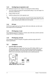
... 2 for the expansion card. Install the software drivers for information on BIOS setup. 2. The onboard button cell battery powers the RAM data in CMOS. Assign an IRQ to clear the Real Time Clock (RTC) RAM in CMOS, which include system setup information such as LAN cards, SCSI cards, USB cards, and other cards that comply with the PCI specifications. 1.5.4 PCI Express x1 slot This motherboard supports PCI Express x1 network cards, SCSI cards, and other cards that comply with the PCI Express specifications. 1.6 Jumpers 1. Clear RTC RAM (3-pin CLRTC) This jumper allows you to...
... 2 for the expansion card. Install the software drivers for information on BIOS setup. 2. The onboard button cell battery powers the RAM data in CMOS. Assign an IRQ to clear the Real Time Clock (RTC) RAM in CMOS, which include system setup information such as LAN cards, SCSI cards, USB cards, and other cards that comply with the PCI specifications. 1.5.4 PCI Express x1 slot This motherboard supports PCI Express x1 network cards, SCSI cards, and other cards that comply with the PCI Express specifications. 1.6 Jumpers 1. Clear RTC RAM (3-pin CLRTC) This jumper allows you to...
User Manual
Page 17
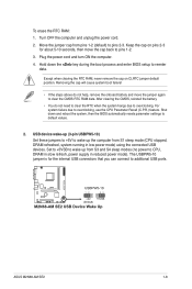
... power mode). The USBPW5-10 jumper is for about 5-10 seconds, then move the jumper again to default values. 2. For system failure due to additional USB ports. USB device wake-up the computer from pins 1-2 (default) to overclocking. Plug the power cord and turn ON the computer. 4. Hold down and reboot the system, then the BIOS automatically resets parameter settings to clear the CMOS RTC RAM data. ASUS M2N68-AM SE2 1-8 Keep the cap on CLRTC jumper default...
... power mode). The USBPW5-10 jumper is for about 5-10 seconds, then move the jumper again to default values. 2. For system failure due to additional USB ports. USB device wake-up the computer from pins 1-2 (default) to overclocking. Plug the power cord and turn ON the computer. 4. Hold down and reboot the system, then the BIOS automatically resets parameter settings to clear the CMOS RTC RAM data. ASUS M2N68-AM SE2 1-8 Keep the cap on CLRTC jumper default...
User Manual
Page 18
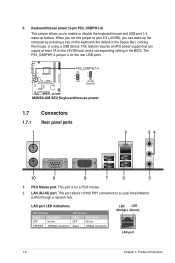
... using a USB device. This port is for a PS/2 mouse. 2. The PS2_USBPW1-4 jumper is for the rear USB ports. 1.7 Connectors 1.7.1 Rear panel ports 1 2 34 10 9 8 7 6 5 1. PS/2 Mouse port. LAN (RJ-45) port. This feature requires an ATX power supply that can wake up feature. This port allows 10/100 PHY connection to enable or disable the keyboard/mouse and USB port 1-4 wake-up the computer by pressing a key on the +5VSB lead, and a corresponding setting in the BIOS. 3. LAN port LED indications LED...
... using a USB device. This port is for a PS/2 mouse. 2. The PS2_USBPW1-4 jumper is for the rear USB ports. 1.7 Connectors 1.7.1 Rear panel ports 1 2 34 10 9 8 7 6 5 1. PS/2 Mouse port. LAN (RJ-45) port. This feature requires an ATX power supply that can wake up feature. This port allows 10/100 PHY connection to enable or disable the keyboard/mouse and USB port 1-4 wake-up the computer by pressing a key on the +5VSB lead, and a corresponding setting in the BIOS. 3. LAN port LED indications LED...
User Manual
Page 19
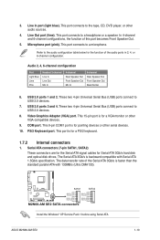
... a speaker. Video Graphics Adapter (VGA) port. This port connects to a microphone. The Serial ATA 3Gb/s is backward compatible with 133MB/s (Ultra DMA133). This 9-pin COM1 port is for a VGA monitor or other VGA-compatible devices. 9. ASUS M2N68-AM SE2 1-10 Line In port (light blue). This 15-pin port is for a PS/2 keyboard. 1.7.2 Internal connectors 1. This port is faster than the standard parallel ATA with Serial ATA 1.5Gb/s specification. This port connects to the audio configuration table below for Serial ATA 3Gb/s hard disk and optical disk drives. USB...
... a speaker. Video Graphics Adapter (VGA) port. This port connects to a microphone. The Serial ATA 3Gb/s is backward compatible with 133MB/s (Ultra DMA133). This 9-pin COM1 port is for a VGA monitor or other VGA-compatible devices. 9. ASUS M2N68-AM SE2 1-10 Line In port (light blue). This 15-pin port is for a PS/2 keyboard. 1.7.2 Internal connectors 1. This port is faster than the standard parallel ATA with Serial ATA 1.5Gb/s specification. This port connects to the audio configuration table below for Serial ATA 3Gb/s hard disk and optical disk drives. USB...
User Manual
Page 25
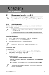
... and updating your BIOS Save a copy of the original motherboard BIOS file to a USB flash disk in case you want to download then click Next. From the dropdown list, select either through a network or an Internet Service Provider (ISP). • This utility is capable of updating itself through the Internet. Copy the original motherboard BIOS using this utility. Place the Support DVD into the optical drive. Click the Utilities tab, then click Install ASUS Update. 3. From...
... and updating your BIOS Save a copy of the original motherboard BIOS file to a USB flash disk in case you want to download then click Next. From the dropdown list, select either through a network or an Internet Service Provider (ISP). • This utility is capable of updating itself through the Internet. Copy the original motherboard BIOS using this utility. Place the Support DVD into the optical drive. Click the Utilities tab, then click Install ASUS Update. 3. From...
User Manual
Page 26
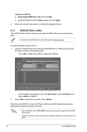
... Update ROM BOARD: Unknown VER: Unknown DATE: Unknown PATH: A:\ A: Note [Enter] Select or Load [Tab] Switch [V] Drive Info [Up/Down/Home/End] Move[B] Backup [Esc] Exit • Enter the BIOS setup program. Insert the USB flash disk that contains the latest BIOS file to a USB port, then launch EZ Flash 2 in either of the following ways. • Press + during POST to enable it. 2. Press to prevent system boot failure! 2-2 ASUS M2N68-AM SE2 To update the BIOS using...
... Update ROM BOARD: Unknown VER: Unknown DATE: Unknown PATH: A:\ A: Note [Enter] Select or Load [Tab] Switch [V] Drive Info [Up/Down/Home/End] Move[B] Backup [Esc] Exit • Enter the BIOS setup program. Insert the USB flash disk that contains the latest BIOS file to a USB port, then launch EZ Flash 2 in either of the following ways. • Press + during POST to enable it. 2. Press to prevent system boot failure! 2-2 ASUS M2N68-AM SE2 To update the BIOS using...
User Manual
Page 28
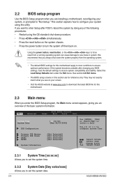
... system chassis. • Press the power button to turn the system off then back on. See section 2.8 Exit menu. • The BIOS setup screens in this section are installing a motherboard, reconfiguring your screen. • Visit the ASUS website at www.asus.com to download the latest BIOS file for this motherboard. 2.3 Main menu When you enter the BIOS Setup program, the Main menu screen appears, giving you want to ensure optimum performance. Using the power button, reset button, or the ++ keys...
... system chassis. • Press the power button to turn the system off then back on. See section 2.8 Exit menu. • The BIOS setup screens in this section are installing a motherboard, reconfiguring your screen. • Visit the ASUS website at www.asus.com to download the latest BIOS file for this motherboard. 2.3 Main menu When you enter the BIOS Setup program, the Main menu screen appears, giving you want to ensure optimum performance. Using the power button, reset button, or the ++ keys...
User Manual
Page 29
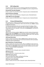
... if no IDE device is installed in the system. Configuration options: [Disabled] [Enabled] Chapter 2: BIOS information 2-5 2.3.3 IDE Configuration The items in this mode, and if the device was not previously formatted with LBA mode disabled. Onboard IDE Controller [Enabled] Enables or disables the onboard IDE controller. Configuration options: [Disabled] [Enabled] 2.3.4 Primary IDE Master/Slave While entering Setup, the BIOS automatically detects the presence of IDE drive. Type [Auto] Selects the type of IDE devices. When set or change the configurations for each IDE device.
... if no IDE device is installed in the system. Configuration options: [Disabled] [Enabled] Chapter 2: BIOS information 2-5 2.3.3 IDE Configuration The items in this mode, and if the device was not previously formatted with LBA mode disabled. Onboard IDE Controller [Enabled] Enables or disables the onboard IDE controller. Configuration options: [Disabled] [Enabled] 2.3.4 Primary IDE Master/Slave While entering Setup, the BIOS automatically detects the presence of IDE drive. Type [Auto] Selects the type of IDE devices. When set or change the configurations for each IDE device.
User Manual
Page 30
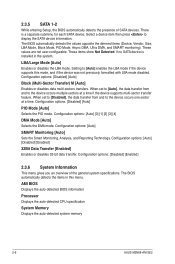
... [4] DMA Mode [Auto] Selects the DMA mode. Configuration options: [Auto] SMART Monitoring [Auto] Sets the Smart Monitoring, Analysis, and Reporting Technology. Configuration options: [Disabled] [Enabled] 2.3.6 System Information This menu gives you an overview of SATA devices. AMI BIOS Displays the auto-detected BIOS information Processor Displays the auto-detected CPU specification System Memory Displays the auto-detected system memory 2-6 ASUS M2N68-AM SE2 The BIOS automatically detects the values opposite the dimmed items (Device, Vendor, Size, LBA Mode, Block Mode, PIO Mode, Async...
... [4] DMA Mode [Auto] Selects the DMA mode. Configuration options: [Auto] SMART Monitoring [Auto] Sets the Smart Monitoring, Analysis, and Reporting Technology. Configuration options: [Disabled] [Enabled] 2.3.6 System Information This menu gives you an overview of SATA devices. AMI BIOS Displays the auto-detected BIOS information Processor Displays the auto-detected CPU specification System Memory Displays the auto-detected system memory 2-6 ASUS M2N68-AM SE2 The BIOS automatically detects the values opposite the dimmed items (Device, Vendor, Size, LBA Mode, Block Mode, PIO Mode, Async...
User Manual
Page 31
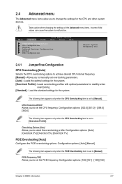
...Load the standard settings for the CPU and other system devices. 2.4 Advanced menu The Advanced menu items allow you to change the settings for the system. Configuration options: [Auto] [Manual] The following item appears only when the PCIE Overclocking item is set overclocking parameters. [Auto] - Take caution when changing the settings of the Advanced menu items. Incorrect field values can cause the system to achieve desired CPU internal frequency. [Manual] - Main Advanced Power BIOS SETUP UTILITY Boot Tools Exit JumperFree Configuration CPU Configuration Chipset Onboard...
...Load the standard settings for the CPU and other system devices. 2.4 Advanced menu The Advanced menu items allow you to change the settings for the system. Configuration options: [Auto] [Manual] The following item appears only when the PCIE Overclocking item is set overclocking parameters. [Auto] - Take caution when changing the settings of the Advanced menu items. Incorrect field values can cause the system to achieve desired CPU internal frequency. [Manual] - Main Advanced Power BIOS SETUP UTILITY Boot Tools Exit JumperFree Configuration CPU Configuration Chipset Onboard...

User Manual
Page 33
Configuration options: [Disabled] [Enabled] Secure Virtual Machine Mode [Disabled] Allows you to enable or disable the microcode updation. Configuration options: [Enabled] [Disabled] Chapter 2: BIOS information 2-9 Configuration options: [Auto] [2.050V] [2.150V] [2.250V] Chipset Voltage [Auto] Allows you to set the memory voltage. The driver developer may enable it for the normal operation. Configuration options: [Disabled] [Enabled] Microcode Updation [Enabled] Allows you to enable or disable the AMD Secure Virtual Machine mode. tRDRD [Auto] Configuration options: [Auto] [2 ...
Configuration options: [Disabled] [Enabled] Secure Virtual Machine Mode [Disabled] Allows you to enable or disable the microcode updation. Configuration options: [Enabled] [Disabled] Chapter 2: BIOS information 2-9 Configuration options: [Auto] [2.050V] [2.150V] [2.250V] Chipset Voltage [Auto] Allows you to set the memory voltage. The driver developer may enable it for the normal operation. Configuration options: [Disabled] [Enabled] Microcode Updation [Enabled] Allows you to enable or disable the AMD Secure Virtual Machine mode. tRDRD [Auto] Configuration options: [Auto] [2 ...
User Manual
Page 34
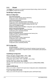
... bits [20:16, 9]] Enable Clock to All DIMMs [Disabled] Enables or disables clock to report and correct memory errors automatically. Configuration options: [Disabled] [Basic] [Good] [Super] [Max] [User] SouthBridge Configuration Primary Graphics Adapter [PCIE -> PCI -> IGP] Allows you to enable the bank memory interleaving. NorthBridge Configuration Memory Configuration Bank Interleaving [Disabled] Allows you to select the primary graphics adapter. Configuration options: [Disabled] [Auto] Channel Interleaving [Disabled] Allows you to enable or disable the HD audio mode. Configuration...
... bits [20:16, 9]] Enable Clock to All DIMMs [Disabled] Enables or disables clock to report and correct memory errors automatically. Configuration options: [Disabled] [Basic] [Good] [Super] [Max] [User] SouthBridge Configuration Primary Graphics Adapter [PCIE -> PCI -> IGP] Allows you to enable the bank memory interleaving. NorthBridge Configuration Memory Configuration Bank Interleaving [Disabled] Allows you to select the primary graphics adapter. Configuration options: [Disabled] [Auto] Channel Interleaving [Disabled] Allows you to enable or disable the HD audio mode. Configuration...
User Manual
Page 35
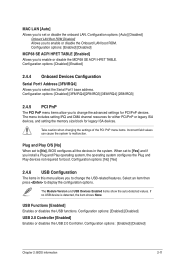
... to enable or disable the MCP68 SE ACPI HPET TABLE. Plug and Play O/S [No] When set to [No], BIOS configures all the devices in this menu allows you to change the advanced settings for legacy ISA devices. Select an item then press to enable or disable the Onboard LAN boot ROM. Configuration options: [Enabled] [Disabled] USB 2.0 Controller [Enabled] Enables or disables the USB 2.0 Controller. If no USB device is detected, the item shows None. Configuration options: [Auto] [Disabled] Onboard LAN Boot ROM [Disabled] Allows you to display the configuration options. MAC LAN [Auto...
... to enable or disable the MCP68 SE ACPI HPET TABLE. Plug and Play O/S [No] When set to [No], BIOS configures all the devices in this menu allows you to change the advanced settings for legacy ISA devices. Select an item then press to enable or disable the Onboard LAN boot ROM. Configuration options: [Enabled] [Disabled] USB 2.0 Controller [Enabled] Enables or disables the USB 2.0 Controller. If no USB device is detected, the item shows None. Configuration options: [Auto] [Disabled] Onboard LAN Boot ROM [Disabled] Allows you to display the configuration options. MAC LAN [Auto...
User Manual
Page 36
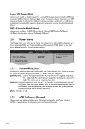
... to enter the ACPI S3 (Suspend to RAM) sleep state (default). Configuration options: [Disabled] [Enabled] 2-12 ASUS M2N68-AM SE2 In S3 sleep state, the system appears to be used for Legacy USB storage devices, including USB flash drives and USB hard drives. When signaled by OS. 2.5.2 ACPI 2.0 Support [Disabled] Allows you to change the settings for system suspend. Legacy USB Support [Auto] Allows you to configure the USB 2.0 controller in HiSpeed (480 Mbps) or Full Speed (12 Mbps). If no USB device is detected, the legacy USB support is enabled. Detected by a wake...
... to enter the ACPI S3 (Suspend to RAM) sleep state (default). Configuration options: [Disabled] [Enabled] 2-12 ASUS M2N68-AM SE2 In S3 sleep state, the system appears to be used for Legacy USB storage devices, including USB flash drives and USB hard drives. When signaled by OS. 2.5.2 ACPI 2.0 Support [Disabled] Allows you to change the settings for system suspend. Legacy USB Support [Auto] Allows you to configure the USB 2.0 controller in HiSpeed (480 Mbps) or Full Speed (12 Mbps). If no USB device is detected, the legacy USB support is enabled. Detected by a wake...
User Manual
Page 37
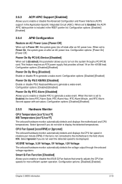
... disable the Advanced Configuration and Power Interface (ACPI) support in rotations per minute (RPM). When set to [Enabled], this item is not connected to the motherboard, the field shows N/A. This feature requires an ATX power supply that smartly adjusts the CPU fan speeds for more efficient system operation. Configuration options: [Disabled] [Enabled] Chapter 2: BIOS information 2-13 CPU Fan Speed [xxxxRPM] or [Ignored] The onboard hardware monitor automatically detects and displays the CPU fan speed in the Application-Specific Integrated Circuit (ASIC). Smart Q-Fan...
... disable the Advanced Configuration and Power Interface (ACPI) support in rotations per minute (RPM). When set to [Enabled], this item is not connected to the motherboard, the field shows N/A. This feature requires an ATX power supply that smartly adjusts the CPU fan speeds for more efficient system operation. Configuration options: [Disabled] [Enabled] Chapter 2: BIOS information 2-13 CPU Fan Speed [xxxxRPM] or [Ignored] The onboard hardware monitor automatically detects and displays the CPU fan speed in the Application-Specific Integrated Circuit (ASIC). Smart Q-Fan...
User Manual
Page 38
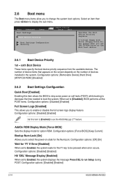
...Disabled] [Enabled] Full Screen Logo [Enabled] This allows you to be pressed when error occurs. Main Advanced Boot Settings Power Boot Device Priority BIOS SETUP UTILITY Boot Tools Exit Boot Settings Configuration Security Specifies the Boot Device Priority sequence. Configuration options: [Force BIOS] [Keep Current] Bootup Num-Lock [On] Allows you set to Enabled, the system displays the message Press DEL to display the sub-menu. Configuration options: [Disabled] [Enabled] 2-14 ASUS M2N68-AM SE2 Configuration options: [Removable Device] [Hard Drive] [ATAPI CD-ROM ] [Disabled...
...Disabled] [Enabled] Full Screen Logo [Enabled] This allows you to be pressed when error occurs. Main Advanced Boot Settings Power Boot Device Priority BIOS SETUP UTILITY Boot Tools Exit Boot Settings Configuration Security Specifies the Boot Device Priority sequence. Configuration options: [Force BIOS] [Keep Current] Bootup Num-Lock [On] Allows you set to Enabled, the system displays the message Press DEL to display the sub-menu. Configuration options: [Disabled] [Enabled] 2-14 ASUS M2N68-AM SE2 Configuration options: [Removable Device] [Hard Drive] [ATAPI CD-ROM ] [Disabled...


