
User Manual
Page 1
R KN97-X Pentium® II ATX Motherboard USER'S MANUAL
R KN97-X Pentium® II ATX Motherboard USER'S MANUAL
User Manual
Page 4
... DIMM 19 SIMM Memory Installation 20 DIMM Memory Installation 21 3. Jumpers 14 Jumper Settings 15 2. FEATURES 8 Features of the ASUS KN97-X Motherboard 8 Parts of the ASUS KN97-X Motherboard 12 Installation Steps 14 1. Central Processing Unit (CPU 22 4. External Connectors 28 Power Connection Procedures 35 IV. Expansion Cards ...DMA Channels for ISA Cards 27 ISA Cards and Hardware Monitor 27 5. INSTALLATION 12 Map of the ASUS KN97-X Motherboard 11 III. BIOS SOFTWARE 36 Support Software 36 Flash Memory Writer Utility 36 Main Menu 36 Advanced Features Menu 37 ...
... DIMM 19 SIMM Memory Installation 20 DIMM Memory Installation 21 3. Jumpers 14 Jumper Settings 15 2. FEATURES 8 Features of the ASUS KN97-X Motherboard 8 Parts of the ASUS KN97-X Motherboard 12 Installation Steps 14 1. Central Processing Unit (CPU 22 4. External Connectors 28 Power Connection Procedures 35 IV. Expansion Cards ...DMA Channels for ISA Cards 27 ISA Cards and Hardware Monitor 27 5. INSTALLATION 12 Map of the ASUS KN97-X Motherboard 11 III. BIOS SOFTWARE 36 Support Software 36 Flash Memory Writer Utility 36 Main Menu 36 Advanced Features Menu 37 ...
User Manual
Page 7
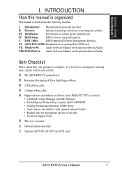
...Installation of the files • Technical Support Form This user's manual Optional infrared module Optional ASUS PCI-SC200 Fast-SCSI card ASUS KN97-X User's Manual 7 The ASUS KN97-X motherboard Retention Mechanism & Heat Sink Support Brace 1 IDE ribbon cable 1 floppy ribbon cable Support ...that your retailer. Windows 95: Audio Software Manual (with optional onboard Audio) VIII. Installation: Instructions on setting up the motherboard. DMI Utility: BIOS supported Desktop Management Interface VI. INTRODUCTION (Manual / Checklist) I. If you discover damaged or missing items...
...Installation of the files • Technical Support Form This user's manual Optional infrared module Optional ASUS PCI-SC200 Fast-SCSI card ASUS KN97-X User's Manual 7 The ASUS KN97-X motherboard Retention Mechanism & Heat Sink Support Brace 1 IDE ribbon cable 1 floppy ribbon cable Support ...that your retailer. Windows 95: Audio Software Manual (with optional onboard Audio) VIII. Installation: Instructions on setting up the motherboard. DMI Utility: BIOS supported Desktop Management Interface VI. INTRODUCTION (Manual / Checklist) I. If you discover damaged or missing items...
User Manual
Page 8
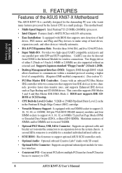
... hard drives, PS/2 mouse, and Plug and Play devices to the Infrared Module for wireless interface. • Concurrent PCI - Two floppy drives of the ASUS KN97-X Motherboard The ASUS KN97-X is available for the demanding PC user who wants many features processed by the fastest CPU in two channels, provides faster data transfer rates, and...
... hard drives, PS/2 mouse, and Plug and Play devices to the Infrared Module for wireless interface. • Concurrent PCI - Two floppy drives of the ASUS KN97-X Motherboard The ASUS KN97-X is available for the demanding PC user who wants many features processed by the fastest CPU in two channels, provides faster data transfer rates, and...
User Manual
Page 9
... monitored for future processors, so monitoring is necessary to ensure proper system configuration and management. • System Resources Alert - ASUS KN97-X User's Manual 9 The system resource monitor will warn the user before the system resources are monitored to ensure stable current to... is completed upon boot-up to avoid any failures triggered by extremely high temperature. • Voltage Monitoring and Alert - ASUS KN97 series of motherboards were designed to cooperate with BIOS, chipset, and flash EPROM to disable write permission when the system's initialization stage is...
... monitored for future processors, so monitoring is necessary to ensure proper system configuration and management. • System Resources Alert - ASUS KN97-X User's Manual 9 The system resource monitor will warn the user before the system resources are monitored to ensure stable current to... is completed upon boot-up to avoid any failures triggered by extremely high temperature. • Voltage Monitoring and Alert - ASUS KN97 series of motherboards were designed to cooperate with BIOS, chipset, and flash EPROM to disable write permission when the system's initialization stage is...
User Manual
Page 11
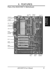
COM 2 Optional T:Joystick/Midi B:Out/In/Mic 5 PCI Slots Multi-I/O Optional 3D Sound Optional Creative Labs Audio 3 ISA Slots 1 DIMM Socket Intel's 440FX PCIset Pentium II CPU Slot Floppy / IDE Intel PIIX3 PCIset Hardware Monitor Programmable Flash ROM ASUS KN97-X User's Manual 11 FEATURES Parts of Board) II. B: Serial Conn. II. FEATURES (Parts of the ASUS KN97-X Motherboard T: PS/2 Mouse B: PS/2 Keyboard T: USB Port 1 B: USB Port 2 COM 1 T: Parallel Conn.
COM 2 Optional T:Joystick/Midi B:Out/In/Mic 5 PCI Slots Multi-I/O Optional 3D Sound Optional Creative Labs Audio 3 ISA Slots 1 DIMM Socket Intel's 440FX PCIset Pentium II CPU Slot Floppy / IDE Intel PIIX3 PCIset Hardware Monitor Programmable Flash ROM ASUS KN97-X User's Manual 11 FEATURES Parts of Board) II. B: Serial Conn. II. FEATURES (Parts of the ASUS KN97-X Motherboard T: PS/2 Mouse B: PS/2 Keyboard T: USB Port 1 B: USB Port 2 COM 1 T: Parallel Conn.
User Manual
Page 12
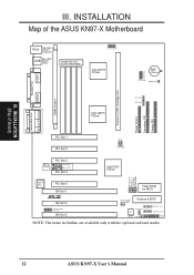
... Power Supply 01234 CPU Voltage ID Intel 440FX PCIset BF0 BF1 BF2 BF3 BUS FREQ. III. INSTALLATION Map of Board) III. INSTALLATION (Map of the ASUS KN97-X Motherboard COM 1 Top: Mouse PS/2 Bottom: Keyboard Top: USB 1 USB Bottom: USB 2 Board Power Input for BIOS R ISA Slot 2 Creative® Modem Connector ISA Slot 3 Chasis... Chassis Fan Volume Control Infrared Connect Hardware Monitor IDE LED Panel NOTE: The items in Outline are available only with the optional onboard Audio. 12 ASUS KN97-X User's Manual
... Power Supply 01234 CPU Voltage ID Intel 440FX PCIset BF0 BF1 BF2 BF3 BUS FREQ. III. INSTALLATION Map of Board) III. INSTALLATION (Map of the ASUS KN97-X Motherboard COM 1 Top: Mouse PS/2 Bottom: Keyboard Top: USB 1 USB Bottom: USB 2 Board Power Input for BIOS R ISA Slot 2 Creative® Modem Connector ISA Slot 3 Chasis... Chassis Fan Volume Control Infrared Connect Hardware Monitor IDE LED Panel NOTE: The items in Outline are available only with the optional onboard Audio. 12 ASUS KN97-X User's Manual

User Manual
Page 13
... conflicts will occur. *PCI NOTE: PCI slots 4&5 share the same interrupt number (INT#) so PCI cards on these PCI cards does not use an INT#. ASUS KN97-X User's Manual 13 INSTALLATION Jumpers 1) IOEN 2) BBLKW 3) AUDIO (optional) 4) VOLADJ (optional) 5) RTCLR 6) BATTERY TEST 7) FS0, FS1 8) BF0, BF1, BF2,...) p. 31 Power LED (3-pins) & Keyboard Lock Switch (2-pins) p. 31 Speaker Output Connector (4-pins) p. 32 Infrared Port Module Connector p. 32 Motherboard Power Connector (20-pin Block) *ISA NOTE: The onboard hardware monitor uses the address 290H so legacy ISA cards must be able to share an...
... conflicts will occur. *PCI NOTE: PCI slots 4&5 share the same interrupt number (INT#) so PCI cards on these PCI cards does not use an INT#. ASUS KN97-X User's Manual 13 INSTALLATION Jumpers 1) IOEN 2) BBLKW 3) AUDIO (optional) 4) VOLADJ (optional) 5) RTCLR 6) BATTERY TEST 7) FS0, FS1 8) BF0, BF1, BF2,...) p. 31 Power LED (3-pins) & Keyboard Lock Switch (2-pins) p. 31 Speaker Output Connector (4-pins) p. 32 Infrared Port Module Connector p. 32 Motherboard Power Connector (20-pin Block) *ISA NOTE: The onboard hardware monitor uses the address 290H so legacy ISA cards must be able to share an...

User Manual
Page 14
... 1 for locations of following steps: 1. The jumpers will be described numerically such as diagramed. INSTALLATION (Jumpers) WARNING: Computer motherboards and components contain very delicate Integrated Circuit (IC) chips. Settings with two jumper numbers require that came with three pins. III... grounded source to touch the IC chips, leads, or circuitry. 3. Jumpers Several hardware settings are separated from the system. 14 ASUS KN97-X User's Manual To connect the pins, simply place a plastic jumper cap over the two pins as [----], [1-2], [2-3] for Open...
... 1 for locations of following steps: 1. The jumpers will be described numerically such as diagramed. INSTALLATION (Jumpers) WARNING: Computer motherboards and components contain very delicate Integrated Circuit (IC) chips. Settings with two jumper numbers require that came with three pins. III... grounded source to touch the IC chips, leads, or circuitry. 3. Jumpers Several hardware settings are separated from the system. 14 ASUS KN97-X User's Manual To connect the pins, simply place a plastic jumper cap over the two pins as [----], [1-2], [2-3] for Open...
User Manual
Page 17
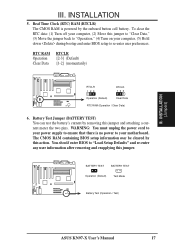
... on your computer, (5) Hold down during bootup and enter BIOS setup to your computer, (2) Move this jumper. To clear the RTC data: (1) Turn off your motherboard. BATTERY TEST BATTERY TEST Operation (Default) Test Mode Battery Test (Operation / Test) ASUS KN97-X User's Manual 17 III. INSTALLATION (Jumpers) III.
... on your computer, (5) Hold down during bootup and enter BIOS setup to your computer, (2) Move this jumper. To clear the RTC data: (1) Turn off your motherboard. BATTERY TEST BATTERY TEST Operation (Default) Test Mode Battery Test (Operation / Test) ASUS KN97-X User's Manual 17 III. INSTALLATION (Jumpers) III.
User Manual
Page 19
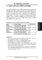
System Memory (SIMM and DIMM) This motherboard supports four 72-pin SIMMs (Single Inline Memory Modules) of either 60ns or 70ns Fast Page Mode (FPM) (Asymmetric or Symmetric), Enhanced Data Output (EDO), ... Modules (DIMMs). A new feature is required through "Auto Configuration" in each bank contains two of SIMMs and/or DIMMs must set Auto Configuration to 256MB. ASUS KN97-X User's Manual 19 Maximum memory of the same size memory modules. SIMM memory modules with more than 24 chips per module. INSTALLATION 2. INSTALLATION (System Memory...
System Memory (SIMM and DIMM) This motherboard supports four 72-pin SIMMs (Single Inline Memory Modules) of either 60ns or 70ns Fast Page Mode (FPM) (Asymmetric or Symmetric), Enhanced Data Output (EDO), ... Modules (DIMMs). A new feature is required through "Auto Configuration" in each bank contains two of SIMMs and/or DIMMs must set Auto Configuration to 256MB. ASUS KN97-X User's Manual 19 Maximum memory of the same size memory modules. SIMM memory modules with more than 24 chips per module. INSTALLATION 2. INSTALLATION (System Memory...
User Manual
Page 21
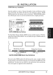
... in the orientation as shown. SDRAM DIMM modules have different pint contact on each side and therefore have the same pin contact on the motherboard. ASUS KN97-X User's Manual 21 You can identify the type of the breaks, the module will shift between left, center, or right to identify... Extended Data Output (EDO) DRAM. You must be inserted into the DIMM slot on both sides. Four clock signals are different on this motherboard. Because the number of pins are supported on either side of DIMM module by the illustration below: III. DRAM SIMM modules have a higher...
... in the orientation as shown. SDRAM DIMM modules have different pint contact on each side and therefore have the same pin contact on the motherboard. ASUS KN97-X User's Manual 21 You can identify the type of the breaks, the module will shift between left, center, or right to identify... Extended Data Output (EDO) DRAM. You must be inserted into the DIMM slot on both sides. Four clock signals are different on this motherboard. Because the number of pins are supported on either side of DIMM module by the illustration below: III. DRAM SIMM modules have a higher...

User Manual
Page 22
...Bar Heatsink Support Base/Top Bar (Items 4-7) Pentium II Processor Heatsink (Item 8) Intel Pentium II Processor in an SEC Cartridge (Item 9) 22 ASUS KN97-X User's Manual Heatsink bottom Groove for your reference. WARNING: Without sufficient air circulation, the SEC cartridge may be slightly different.) Lock Holes (1)...Installed) Larger Fin should check to see that you have the same item numbers next to both the SEC cartridge and the motherboard. The SEC slot is not compatible with either the power supply fan or a secondary fan circulating air across the SEC cartridge's passive heat ...
...Bar Heatsink Support Base/Top Bar (Items 4-7) Pentium II Processor Heatsink (Item 8) Intel Pentium II Processor in an SEC Cartridge (Item 9) 22 ASUS KN97-X User's Manual Heatsink bottom Groove for your reference. WARNING: Without sufficient air circulation, the SEC cartridge may be slightly different.) Lock Holes (1)...Installed) Larger Fin should check to see that you have the same item numbers next to both the SEC cartridge and the motherboard. The SEC slot is not compatible with either the power supply fan or a secondary fan circulating air across the SEC cartridge's passive heat ...

User Manual
Page 23
... of the KN97-X Motherboard from Mount Bridge (1&2) Pentium II processor SEC slot View of the motherboard. WARNING: Excessive torque may damage your motherboard. Heatsink Support Base Pin (5&6) Support Base (7) Screw from the Manufacturer Installing the Pentium II Processor: 1. INSTALLATION (CPU) III. nism over the two chipsets in place and Captive Nut being tightened ASUS KN97-X User...
... of the KN97-X Motherboard from Mount Bridge (1&2) Pentium II processor SEC slot View of the motherboard. WARNING: Excessive torque may damage your motherboard. Heatsink Support Base Pin (5&6) Support Base (7) Screw from the Manufacturer Installing the Pentium II Processor: 1. INSTALLATION (CPU) III. nism over the two chipsets in place and Captive Nut being tightened ASUS KN97-X User...
User Manual
Page 24
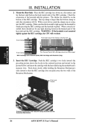
... light showing between the thermal pad of the SEC cartridge. SEC Cartridge with Heatsink (Side) SEC Cartridge with the heat sink facing the motherboard's memory slots. Push down on a flat surface and lay the heat sink flush on the bottom of the heat sink and the SEC... below) and insert the cartridge with Heatsink (Top) 3. With a screw driver, push the clamps one at a time into the Retention Mechanism. 24 ASUS KN97-X User's Manual When correctly installed, there should not have a gap! Check the orientation of the SEC cartridge. WARNING: If the heatsink is larger than...
... light showing between the thermal pad of the SEC cartridge. SEC Cartridge with Heatsink (Side) SEC Cartridge with the heat sink facing the motherboard's memory slots. Push down on a flat surface and lay the heat sink flush on the bottom of the heat sink and the SEC... below) and insert the cartridge with Heatsink (Top) 3. With a screw driver, push the clamps one at a time into the Retention Mechanism. 24 ASUS KN97-X User's Manual When correctly installed, there should not have a gap! Check the orientation of the SEC cartridge. WARNING: If the heatsink is larger than...
User Manual
Page 26
...power supply when adding or removing expansion cards or other system components. INSTALLATION 4. sible future use at the same time. 26 ASUS KN97-X User's Manual Secure the card on your computer will experience problems when those two devices are then used and free IRQs. ...settings that you a "Device Manager" tab. Remove the bracket on a specific device give you "Resources" tab which gives you unplug your motherboard and expansion cards. Keep the bracket for expansion cards. Carefully align the card's connectors and press firmly. 6. Setup the BIOS if necessary ...
...power supply when adding or removing expansion cards or other system components. INSTALLATION 4. sible future use at the same time. 26 ASUS KN97-X User's Manual Secure the card on your computer will experience problems when those two devices are then used and free IRQs. ...settings that you a "Device Manager" tab. Remove the bracket on a specific device give you "Resources" tab which gives you unplug your motherboard and expansion cards. Keep the bracket for expansion cards. Carefully align the card's connectors and press firmly. 6. Setup the BIOS if necessary ...
User Manual
Page 27
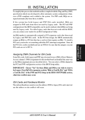
... automatically assigns an IRQ to a PCI slot that has a card in it that the jumpers on this motherboard has complied with the BIOS, you need to PCI expansion cards after those available. You can select a DMA... BIOS SOFTWARE section, otherwise conflicts may also need to the system. INSTALLATION To simplify this process this motherboard use this motherboard are being used by Legacy cards. The PCI and PNP configuration of the BIOS Setup utility. To ... not use an INTA #, be used by Legacy cards. ASUS KN97-X User's Manual 27 INSTALLATION (DMA Channels) III.
... automatically assigns an IRQ to a PCI slot that has a card in it that the jumpers on this motherboard has complied with the BIOS, you need to PCI expansion cards after those available. You can select a DMA... BIOS SOFTWARE section, otherwise conflicts may also need to the system. INSTALLATION To simplify this process this motherboard use this motherboard are being used by Legacy cards. The PCI and PNP configuration of the BIOS Setup utility. To ... not use an INTA #, be used by Legacy cards. ASUS KN97-X User's Manual 27 INSTALLATION (DMA Channels) III.
User Manual
Page 28
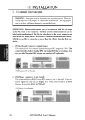
Pin 1 is the side closest to mini DIN adapter on hard drives and floppy drives. PS/2 Mouse (6-pin Female) 28 ASUS KN97-X User's Manual External Connectors WARNING: Some pins are labeled on the Pin 1 side of the connectors are used for a standard keyboard using..." in "Map of the BIOS SOFTWARE. INSTALLATION 5. IMPORTANT: Ribbon cables should always be less than 18in. (46cm), with the red stripe on the motherboard. PS/2 Keyboard Connector (6-pin Female) This connection is detected. If not detected, expansion cards can use a DIN to the power connector on standard AT...
Pin 1 is the side closest to mini DIN adapter on hard drives and floppy drives. PS/2 Mouse (6-pin Female) 28 ASUS KN97-X User's Manual External Connectors WARNING: Some pins are labeled on the Pin 1 side of the connectors are used for a standard keyboard using..." in "Map of the BIOS SOFTWARE. INSTALLATION 5. IMPORTANT: Ribbon cables should always be less than 18in. (46cm), with the red stripe on the motherboard. PS/2 Keyboard Connector (6-pin Female) This connection is detected. If not detected, expansion cards can use a DIN to the power connector on standard AT...
User Manual
Page 31
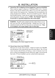
... so that the chassis has been opened. The red wire should be positive, while the black should be different. WARNING: The CPU and/or motherboard will indicate to the system that the heat sink fins allow airflow to be used . These are not jumpers, do not place jumper caps over...expansion slots. NOTE: The "Rotation" signal is for an open alarm lead CHASSIS +5V GND ASUS KN97-X User's Manual 31 INSTALLATION 9. A high level signal to the CHASSIS lead will overheat if there is minimal to the motherboard and/or the CPU fan if these pins. Chassis Open Alarm Lead (CHASSIS) This lead ...
... so that the chassis has been opened. The red wire should be positive, while the black should be different. WARNING: The CPU and/or motherboard will indicate to the system that the heat sink fins allow airflow to be used . These are not jumpers, do not place jumper caps over...expansion slots. NOTE: The "Rotation" signal is for an open alarm lead CHASSIS +5V GND ASUS KN97-X User's Manual 31 INSTALLATION 9. A high level signal to the CHASSIS lead will overheat if there is minimal to the motherboard and/or the CPU fan if these pins. Chassis Open Alarm Lead (CHASSIS) This lead ...

User Manual
Page 34
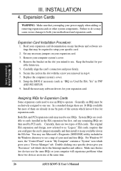
The plug from the module to the motherboard according to select whether UART2 is directed for use with COM2 or IrDA. You may experience difficulty in powering on the Back View and connect a ... 12.0V 5VSB PW-0K GND 5.0V GND 5.0V GND 3.3V 3.3V 5.0V 5.0V -5.0V GND GND GND PS-ON GND -12.0V 3.3V 34 ASUS KN97-X User's Manual ATX Power Supply Connector (20-pin block) This connector connects to the motherboard. 20.
The plug from the module to the motherboard according to select whether UART2 is directed for use with COM2 or IrDA. You may experience difficulty in powering on the Back View and connect a ... 12.0V 5VSB PW-0K GND 5.0V GND 5.0V GND 3.3V 3.3V 5.0V 5.0V -5.0V GND GND GND PS-ON GND -12.0V 3.3V 34 ASUS KN97-X User's Manual ATX Power Supply Connector (20-pin block) This connector connects to the motherboard. 20.


