
User Manual
Page 1
R KN97-X Pentium® II ATX Motherboard USER'S MANUAL
R KN97-X Pentium® II ATX Motherboard USER'S MANUAL
User Manual
Page 2
... are released for each board design represented by the third digit in the manual revision number. Product Name: ASUS KN97-X Manual Revision: 1.04 Release Date: April 1997 2 ASUS KN97-X User's Manual USER'S NOTICE No part of this product, including the product and software may be liable for any loss or profits, loss of business, loss of ...
... are released for each board design represented by the third digit in the manual revision number. Product Name: ASUS KN97-X Manual Revision: 1.04 Release Date: April 1997 2 ASUS KN97-X User's Manual USER'S NOTICE No part of this product, including the product and software may be liable for any loss or profits, loss of business, loss of ...

User Manual
Page 3
....tw Technical Support: Fax: 886-2-895-9254 BBS: 886-2-896-4667 Email: tsd@asus.com.tw WWW: http://www.asus.com.tw/ Gopher: gopher.asus.com.tw FTP: ftp.asus.com.tw/pub/ASUS ASUS COMPUTER INTERNATIONAL Marketing Info: Address: 721 Charcot Avenue, San Jose, CA 95131, USA ... tsd-usa@asus.com.tw ASUS COMPUTER GmbH Marketing Info: Address: Harkort Str. 25, 40880 Ratingen, BRD, Germany Telephone: 49-2102-445011 Fax: 49-2102-442066 Email: info-ger@asus.com.tw Technical Support: BBS: 49-2102-448690 Email: tsd-ger@asus.com.tw ASUS KN97-X User's Manual 3 ASUS CONTACT INFORMATION ...
....tw Technical Support: Fax: 886-2-895-9254 BBS: 886-2-896-4667 Email: tsd@asus.com.tw WWW: http://www.asus.com.tw/ Gopher: gopher.asus.com.tw FTP: ftp.asus.com.tw/pub/ASUS ASUS COMPUTER INTERNATIONAL Marketing Info: Address: 721 Charcot Avenue, San Jose, CA 95131, USA ... tsd-usa@asus.com.tw ASUS COMPUTER GmbH Marketing Info: Address: Harkort Str. 25, 40880 Ratingen, BRD, Germany Telephone: 49-2102-445011 Fax: 49-2102-442066 Email: info-ger@asus.com.tw Technical Support: BBS: 49-2102-448690 Email: tsd-ger@asus.com.tw ASUS KN97-X User's Manual 3 ASUS CONTACT INFORMATION ...
User Manual
Page 4
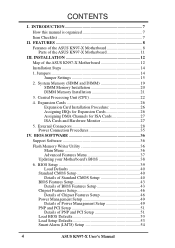
... PNP and PCI Setup 51 Load BIOS Defaults 53 Load Setup Defaults 53 Smart Alarm (LM78) Setup 54 4 ASUS KN97-X User's Manual FEATURES 8 Features of the ASUS KN97-X Motherboard 8 Parts of the ASUS KN97-X Motherboard 11 III. INTRODUCTION 7 How this manual is organized 7 Item Checklist 7 II. Central Processing Unit (CPU 22 4. BIOS SOFTWARE 36 Support Software 36 Flash...
... PNP and PCI Setup 51 Load BIOS Defaults 53 Load Setup Defaults 53 Smart Alarm (LM78) Setup 54 4 ASUS KN97-X User's Manual FEATURES 8 Features of the ASUS KN97-X Motherboard 8 Parts of the ASUS KN97-X Motherboard 11 III. INTRODUCTION 7 How this manual is organized 7 Item Checklist 7 II. Central Processing Unit (CPU 22 4. BIOS SOFTWARE 36 Support Software 36 Flash...
User Manual
Page 5
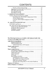
... Environment variable 15 BLASTER Environment Variable 15 MIDI Environment Variable 16 Maximum Recording Rates for the Audio Hardware ......... 16 Windows 95 Software I DOS & Windows 3.x Software I ASUS KN97-X User's Manual 5 DESKTOP MANAGEMENT 58 Desktop Management Interface (DMI 58 Introducing the ASUS DMI Configuration Utility 58 System Requirements 58 Using the...
... Environment variable 15 BLASTER Environment Variable 15 MIDI Environment Variable 16 Maximum Recording Rates for the Audio Hardware ......... 16 Windows 95 Software I DOS & Windows 3.x Software I ASUS KN97-X User's Manual 5 DESKTOP MANAGEMENT 58 Desktop Management Interface (DMI 58 Introducing the ASUS DMI Configuration Utility 58 System Requirements 58 Using the...
User Manual
Page 6
... to try to operate this unit not expressly approved by the party responsible for help. Changes or modifications to this equipment. Canadian Department of Communications. 6 ASUS KN97-X User's Manual However, there is connected. • Consult the dealer or an experienced radio/TV technician for compliance could void the user's authority to correct the...
... to try to operate this unit not expressly approved by the party responsible for help. Changes or modifications to this equipment. Canadian Department of Communications. 6 ASUS KN97-X User's Manual However, there is connected. • Consult the dealer or an experienced radio/TV technician for compliance could void the user's authority to correct the...
User Manual
Page 7
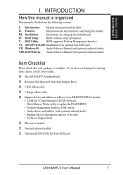
...; Readme files for descriptions and use of an optional Fast-SCSI card. ASUS PCI-SC200: Installation of the files • Technical Support Form This user's manual Optional infrared module Optional ASUS PCI-SC200 Fast-SCSI card ASUS KN97-X User's Manual 7 VII. DMI Utility: BIOS supported Desktop Management Interface VI. INTRODUCTION (Manual / Checklist) I . INTRODUCTION How this product III.
...; Readme files for descriptions and use of an optional Fast-SCSI card. ASUS PCI-SC200: Installation of the files • Technical Support Form This user's manual Optional infrared module Optional ASUS PCI-SC200 Fast-SCSI card ASUS KN97-X User's Manual 7 VII. DMI Utility: BIOS supported Desktop Management Interface VI. INTRODUCTION (Manual / Checklist) I . INTRODUCTION How this product III.
User Manual
Page 8
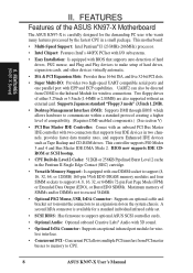
... Play devices to an expansion slot on the system chassis. Concurrent PCI allows multiple PCI transfers from COM2 to CPU. 8 ASUS KN97-X User's Manual UART2 can also be directed from PCI master busses to memory to the Infrared Module for a standard individual infrared cable set....174; Audio with one parallel port with BIOS that supports four IDE devices in a small package. Two floppy drives of the ASUS KN97-X Motherboard The ASUS KN97-X is available for wireless connections. II. A second IrDA connector is carefully designed for wireless interface. • Concurrent PCI -...
... Play devices to an expansion slot on the system chassis. Concurrent PCI allows multiple PCI transfers from COM2 to CPU. 8 ASUS KN97-X User's Manual UART2 can also be directed from PCI master busses to memory to the Infrared Module for a standard individual infrared cable set....174; Audio with one parallel port with BIOS that supports four IDE devices in a small package. Two floppy drives of the ASUS KN97-X Motherboard The ASUS KN97-X is available for wireless connections. II. A second IrDA connector is carefully designed for wireless interface. • Concurrent PCI -...
User Manual
Page 9
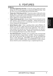
...-generation viruses will warn the user before the system resources are monitored to ensure stable current to prevent possible application crashes. ASUS KN97-X User's Manual 9 Normally, viruses can be set for its normal RPM range and alarm thresholds. • Temperature Monitoring and Alert ... when the system's initialization stage is operating at a safe heat level to present enormous user interfaces and run large applications. ASUS KN97 series of motherboards were designed to cooperate with BIOS, chipset, and flash EPROM to ensure proper system configuration and management. &#...
...-generation viruses will warn the user before the system resources are monitored to ensure stable current to prevent possible application crashes. ASUS KN97-X User's Manual 9 Normally, viruses can be set for its normal RPM range and alarm thresholds. • Temperature Monitoring and Alert ... when the system's initialization stage is operating at a safe heat level to present enormous user interfaces and run large applications. ASUS KN97 series of motherboards were designed to cooperate with BIOS, chipset, and flash EPROM to ensure proper system configuration and management. &#...
User Manual
Page 10
(This page was intentionally left blank) 10 ASUS KN97-X User's Manual
(This page was intentionally left blank) 10 ASUS KN97-X User's Manual
User Manual
Page 11
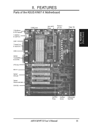
II. FEATURES Parts of Board) II. B: Serial Conn. COM 2 Optional T:Joystick/Midi B:Out/In/Mic 5 PCI Slots Multi-I/O Optional 3D Sound Optional Creative Labs Audio 3 ISA Slots 1 DIMM Socket Intel's 440FX PCIset Pentium II CPU Slot Floppy / IDE Intel PIIX3 PCIset Hardware Monitor Programmable Flash ROM ASUS KN97-X User's Manual 11 FEATURES (Parts of the ASUS KN97-X Motherboard T: PS/2 Mouse B: PS/2 Keyboard T: USB Port 1 B: USB Port 2 COM 1 T: Parallel Conn.
II. FEATURES Parts of Board) II. B: Serial Conn. COM 2 Optional T:Joystick/Midi B:Out/In/Mic 5 PCI Slots Multi-I/O Optional 3D Sound Optional Creative Labs Audio 3 ISA Slots 1 DIMM Socket Intel's 440FX PCIset Pentium II CPU Slot Floppy / IDE Intel PIIX3 PCIset Hardware Monitor Programmable Flash ROM ASUS KN97-X User's Manual 11 FEATURES (Parts of the ASUS KN97-X Motherboard T: PS/2 Mouse B: PS/2 Keyboard T: USB Port 1 B: USB Port 2 COM 1 T: Parallel Conn.
User Manual
Page 12
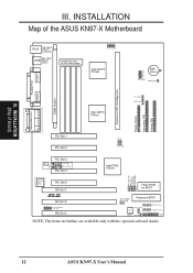
III. INSTALLATION (Map of the ASUS KN97-X Motherboard COM 1 Top: Mouse PS/2 Bottom: Keyboard Top: USB 1 USB Bottom: USB 2 Board Power Input for BIOS R ISA Slot 2 Creative® Modem Connector ISA Slot 3 ... Chassis Fan Volume Control Infrared Connect Hardware Monitor IDE LED Panel NOTE: The items in Outline are available only with the optional onboard Audio. 12 ASUS KN97-X User's Manual CR2032 3 Volt Lithium Cell Battery Test Parallel Port COM 2 DIMM Socket Intel 440FX PCIset CPU_FAN PWR_FAN Pentium II CPU Cartridge Slot Floppy Drives Secondary...
III. INSTALLATION (Map of the ASUS KN97-X Motherboard COM 1 Top: Mouse PS/2 Bottom: Keyboard Top: USB 1 USB Bottom: USB 2 Board Power Input for BIOS R ISA Slot 2 Creative® Modem Connector ISA Slot 3 ... Chassis Fan Volume Control Infrared Connect Hardware Monitor IDE LED Panel NOTE: The items in Outline are available only with the optional onboard Audio. 12 ASUS KN97-X User's Manual CR2032 3 Volt Lithium Cell Battery Test Parallel Port COM 2 DIMM Socket Intel 440FX PCIset CPU_FAN PWR_FAN Pentium II CPU Cartridge Slot Floppy Drives Secondary...

User Manual
Page 13
... number (INT#) so PCI cards on these two slots must be able to share an INT# or make sure that one of Board) III. III. ASUS KN97-X User's Manual 13
... number (INT#) so PCI cards on these two slots must be able to share an INT# or make sure that one of Board) III. III. ASUS KN97-X User's Manual 13

User Manual
Page 14
...: 1. To protect the motherboard and other groups. INSTALLATION Installation Steps Before using your computer when working on the inside. 2. Use the diagrams in this manual instead of jumper caps to connect pins 2&3. III. Install DRAM Modules 3. See "Map of jumpers. INSTALLATION (Jumpers) WARNING: Computer motherboards and components contain...and for locations of the Motherboard" on the bag that both jumpers be sharing pins from other components against damage from the system. 14 ASUS KN97-X User's Manual III. Unplug your computer, you work on the board.
...: 1. To protect the motherboard and other groups. INSTALLATION Installation Steps Before using your computer when working on the inside. 2. Use the diagrams in this manual instead of jumper caps to connect pins 2&3. III. Install DRAM Modules 3. See "Map of jumpers. INSTALLATION (Jumpers) WARNING: Computer motherboards and components contain...and for locations of the Motherboard" on the bag that both jumpers be sharing pins from other components against damage from the system. 14 ASUS KN97-X User's Manual III. Unplug your computer, you work on the board.
User Manual
Page 15
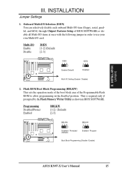
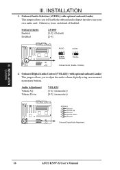
... following jumper in BIOS SOFTWARE. Programming Disabled/Protect Enabled BBLKW [1-2] (Default) [2-3] BBLKW 123 Disabled / Protected (Default) BBLKW 123 Enabled / Program Boot Block Programming (Disable / Enable) ASUS KN97-X User's Manual 15
... following jumper in BIOS SOFTWARE. Programming Disabled/Protect Enabled BBLKW [1-2] (Default) [2-3] BBLKW 123 Disabled / Protected (Default) BBLKW 123 Enabled / Program Boot Block Programming (Disable / Enable) ASUS KN97-X User's Manual 15
User Manual
Page 16
... (Enable / Disable) 4. R R III. Audio Adjustment Volume Up Volume Down VOLADJ [1-2] (momentary) [4-5] (momentary) VOLADJ 1 Ground 2 Volume Up 3 Ground 4 Volume Down 5 Ground Onboard Digital Audio Adjustment 16 ASUS KN97-X User's Manual
... (Enable / Disable) 4. R R III. Audio Adjustment Volume Up Volume Down VOLADJ [1-2] (momentary) [4-5] (momentary) VOLADJ 1 Ground 2 Volume Up 3 Ground 4 Volume Down 5 Ground Onboard Digital Audio Adjustment 16 ASUS KN97-X User's Manual
User Manual
Page 17
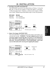
... after removing and reapplying this jumper and attaching a current meter the two pins. BATTERY TEST BATTERY TEST Operation (Default) Test Mode Battery Test (Operation / Test) ASUS KN97-X User's Manual 17 III. RTC RAM Operation Clear Data RTCLR [2-3] (Default) [1-2] (momentarily) R R RTCLR 123 RTCLR 123 Operation (Default) Clear Data RTC RAM (Operation / Clear Data) 6. The...
... after removing and reapplying this jumper and attaching a current meter the two pins. BATTERY TEST BATTERY TEST Operation (Default) Test Mode Battery Test (Operation / Test) ASUS KN97-X User's Manual 17 III. RTC RAM Operation Clear Data RTCLR [2-3] (Default) [1-2] (momentarily) R R RTCLR 123 RTCLR 123 Operation (Default) Clear Data RTC RAM (Operation / Clear Data) 6. The...
User Manual
Page 18
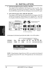
... between the Internal frequency of the CPU and the External frequency (called the BUS Clock) within the CPU. CPU to the onboard power controller. 18 ASUS KN97-X User's Manual Ratio) FS0 FS1 BF3 BF2 BF1 BF0 [2-3] [1-2] [short] [open] [short] [short] [2-3] [1-2] [short] [short] [open] [open] Intel Pentium II CPU Cartridge (233-266MHz 256/512KB...
... between the Internal frequency of the CPU and the External frequency (called the BUS Clock) within the CPU. CPU to the onboard power controller. 18 ASUS KN97-X User's Manual Ratio) FS0 FS1 BF3 BF2 BF1 BF0 [2-3] [1-2] [short] [open] [short] [short] [2-3] [1-2] [short] [short] [open] [open] Intel Pentium II CPU Cartridge (233-266MHz 256/512KB...
User Manual
Page 19
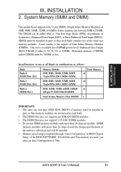
INSTALLATION (System Memory) III. INSTALLATION 2. SIMMs must set Auto Configuration to 256MB. ASUS KN97-X User's Manual 19 The DRAM can be installed in pairs so that each bank contains two of the same size memory modules. One slot is the support ...
INSTALLATION (System Memory) III. INSTALLATION 2. SIMMs must set Auto Configuration to 256MB. ASUS KN97-X User's Manual 19 The DRAM can be installed in pairs so that each bank contains two of the same size memory modules. One slot is the support ...
User Manual
Page 20
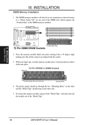
... the sides and the "Metal Clips" should snap on one end of the SIMM slots which requires the "Notched End" of the "Metal Clips". 20 ASUS KN97-X User's Manual INSTALLATION SIMM Memory Installation 1. Bank 0 Bank 1 R III. With your finger tips, rock the memory module into a vertical position so that it clicks into place...
... the sides and the "Metal Clips" should snap on one end of the SIMM slots which requires the "Notched End" of the "Metal Clips". 20 ASUS KN97-X User's Manual INSTALLATION SIMM Memory Installation 1. Bank 0 Bank 1 R III. With your finger tips, rock the memory module into a vertical position so that it clicks into place...


