K8V-MX User's Manual for English Edition
Page 1
Motherboard K8V-MX User Guide
Motherboard K8V-MX User Guide
K8V-MX User's Manual for English Edition
Page 3
Contents Notices vi Safety information vii About this guide viii K8V-MX specifications summary ix Chapter 1: Product Introduction 1.1 Welcome 1-2 1.2 Package contents 1-2 1.3 Special features 1-2 1.3.1 Product highlights 1-2 1.3.2 ASUS unique features 1-4 1.4 Before you proceed 1-5 1.5 Motherboard overview 1-6 1.5.1 Motherboard layout 1-6 1.5.2 Placement direction 1-7 1.5.3 Screw holes 1-7 1.6 Central Processing Unit (CPU 1-8 1.6.1 Overview 1-8 1.6.2 Installing the CPU 1-8 1.7 System memory 1-10 1.7.1 Overview 1-10 1.7.2 Memory con...
Contents Notices vi Safety information vii About this guide viii K8V-MX specifications summary ix Chapter 1: Product Introduction 1.1 Welcome 1-2 1.2 Package contents 1-2 1.3 Special features 1-2 1.3.1 Product highlights 1-2 1.3.2 ASUS unique features 1-4 1.4 Before you proceed 1-5 1.5 Motherboard overview 1-6 1.5.1 Motherboard layout 1-6 1.5.2 Placement direction 1-7 1.5.3 Screw holes 1-7 1.6 Central Processing Unit (CPU 1-8 1.6.1 Overview 1-8 1.6.2 Installing the CPU 1-8 1.7 System memory 1-10 1.7.1 Overview 1-10 1.7.2 Memory con...
K8V-MX User's Manual for English Edition
Page 7
... damage, contact your dealer immediately. • To avoid short circuits, keep paper clips, screws, and staples away from the motherboard, ensure that the power cables for the devices are unplugged before the signal cables are connected. vii Safety Information Electrical safety &#...broken, do not try to fix it can interrupt the grounding circuit. • Set your retailer. Operational safety • Before installing the motherboard and adding devices on a stable surface. • If you add a device. • Before connecting or removing signal cables from connectors, slots...
... damage, contact your dealer immediately. • To avoid short circuits, keep paper clips, screws, and staples away from the motherboard, ensure that the power cables for the devices are unplugged before the signal cables are connected. vii Safety Information Electrical safety &#...broken, do not try to fix it can interrupt the grounding circuit. • Set your retailer. Operational safety • Before installing the motherboard and adding devices on a stable surface. • If you add a device. • Before connecting or removing signal cables from connectors, slots...
K8V-MX User's Manual for English Edition
Page 11
It includes brief explanations of the special attributes of this motherboard. Product Introduction Chapter 1 This chapter describes the features of the motherboard and the new technology it supports.
It includes brief explanations of the special attributes of this motherboard. Product Introduction Chapter 1 This chapter describes the features of the motherboard and the new technology it supports.
K8V-MX User's Manual for English Edition
Page 12
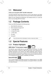
... hardware devices on it another standout in your package with the list below. 1.2 Package Contents Check your K8V-MX package for buying the ASUS® K8V-MX motherboard! Before you for the following items. ASUS K8V-MX motherboard ASUS motherboard support CD 1 x Ultra DMA cable 2 x Serial ATA cables 1 x FDD cable I/O shield User guide If any of the above items is damaged or...
... hardware devices on it another standout in your package with the list below. 1.2 Package Contents Check your K8V-MX package for buying the ASUS® K8V-MX motherboard! Before you for the following items. ASUS K8V-MX motherboard ASUS motherboard support CD 1 x Ultra DMA cable 2 x Serial ATA cables 1 x FDD cable I/O shield User guide If any of the above items is damaged or...
K8V-MX User's Manual for English Edition
Page 13
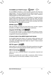
... performance. AGP 8X support AGP 8X (AGP 3.0) is the latest connectiviity standard for next generation components and peripherals. Backwards compatible with the AMD 64 processor. ASUS K8V-MX Motherboard 1-3 VIA K8M800 and VT8237R chipset The VIA K8M800 northbridge is the industryʼs highest performance and most reliable audio solution for business perfessionals, audiophiles, musicians...
... performance. AGP 8X support AGP 8X (AGP 3.0) is the latest connectiviity standard for next generation components and peripherals. Backwards compatible with the AMD 64 processor. ASUS K8V-MX Motherboard 1-3 VIA K8M800 and VT8237R chipset The VIA K8M800 northbridge is the industryʼs highest performance and most reliable audio solution for business perfessionals, audiophiles, musicians...
K8V-MX User's Manual for English Edition
Page 14
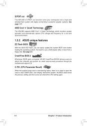
...DOS-based utility or boot from a floppy disk. AMD Cool ʻnʼ Quiet! CrashFree BIOS 2 Whenever BIOS gets corrupted, ASUS CrashFree BIOS2 allows users to powerful speaker systems. See page 1-17. Technology, which monitors system operation and automatically adjusts CPU voltage and frequency..., there is no need to clear CMOS data. S/PDIF out The K8V-MXʼs S/PDIF-out function turns your comoputer into a high-end entertainment system with digital connectivity to reboot the computer and perform an smart auto-recovery procedure through the motherboard support CD.
...DOS-based utility or boot from a floppy disk. AMD Cool ʻnʼ Quiet! CrashFree BIOS 2 Whenever BIOS gets corrupted, ASUS CrashFree BIOS2 allows users to powerful speaker systems. See page 1-17. Technology, which monitors system operation and automatically adjusts CPU voltage and frequency..., there is no need to clear CMOS data. S/PDIF out The K8V-MXʼs S/PDIF-out function turns your comoputer into a high-end entertainment system with digital connectivity to reboot the computer and perform an smart auto-recovery procedure through the motherboard support CD.
K8V-MX User's Manual for English Edition
Page 15
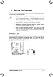
... Proceed Take note of the following precautions before you install or remove any motherboard component. R K8V-MX K8V-MX Onboard LED SB_PWR ON Standby Power OFF Powered Off ASUS K8V-MX Motherboard 1-5 Onboard LED The motherboard comes with the component. • Before you install motherboard components or change any motherboard settings. • Unplug the power cord from the wall socket before touching...
... Proceed Take note of the following precautions before you install or remove any motherboard component. R K8V-MX K8V-MX Onboard LED SB_PWR ON Standby Power OFF Powered Off ASUS K8V-MX Motherboard 1-5 Onboard LED The motherboard comes with the component. • Before you install motherboard components or change any motherboard settings. • Unplug the power cord from the wall socket before touching...
K8V-MX User's Manual for English Edition
Page 16
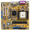
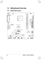
FLOPPY 1.5 Motherboard Overview 1.5.1 Motherboard layout PS/2 T: Mouse B: Keyboard ATX12V COM1 KBPWR CPU_FAN ATXPWR CHA_FAN DDR DIMM1 (64 bit, 184-pin module) DDR DIMM2 (64 bit, 184-pin module) PARALLEL PORT Socket 754 VGA USB1 USB2 Bottom: USB3 USB4 Top: RJ-45 Top:Line In Center:Line Out Below:Mic In USBPW12 USBPW34 VIA K8M800 AGP R FP_AUDIO AD1888 SPDIF AUX CD PCI1 K8V-MX PCI2 PCI3 USBPW56 USBPW78 USB78 CR2032 3V Lithium Cell CMOS Power USB56 SB_PWR VIA VT8237R SATA2 SATA1 Super I/O CLRTC 4Mbit BIOS PANEL PRI_IDE SEC_IDE 1-6 Chapter 1: Product Introduction
FLOPPY 1.5 Motherboard Overview 1.5.1 Motherboard layout PS/2 T: Mouse B: Keyboard ATX12V COM1 KBPWR CPU_FAN ATXPWR CHA_FAN DDR DIMM1 (64 bit, 184-pin module) DDR DIMM2 (64 bit, 184-pin module) PARALLEL PORT Socket 754 VGA USB1 USB2 Bottom: USB3 USB4 Top: RJ-45 Top:Line In Center:Line Out Below:Mic In USBPW12 USBPW34 VIA K8M800 AGP R FP_AUDIO AD1888 SPDIF AUX CD PCI1 K8V-MX PCI2 PCI3 USBPW56 USBPW78 USB78 CR2032 3V Lithium Cell CMOS Power USB56 SB_PWR VIA VT8237R SATA2 SATA1 Super I/O CLRTC 4Mbit BIOS PANEL PRI_IDE SEC_IDE 1-6 Chapter 1: Product Introduction
K8V-MX User's Manual for English Edition
Page 17
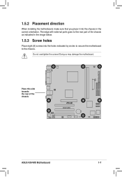
Place this side towards the rear of the chassis as indicated in the correct orientation. Doing so may damage the motherboard. The edge with external ports goes to the rear part of the chassis R K8V-MX ASUS K8V-MX Motherboard 1-7 1.5.2 Placement direction When installing the motherboard, make sure that you place it into the chassis in the image below. 1.5.3 Screw holes Place eight (8) screws into the holes indicated by circles to secure the motherboard to the chassis. Do not overtighten the screws!
Place this side towards the rear of the chassis as indicated in the correct orientation. Doing so may damage the motherboard. The edge with external ports goes to the rear part of the chassis R K8V-MX ASUS K8V-MX Motherboard 1-7 1.5.2 Placement direction When installing the motherboard, make sure that you place it into the chassis in the image below. 1.5.3 Screw holes Place eight (8) screws into the holes indicated by circles to secure the motherboard to the chassis. Do not overtighten the screws!
K8V-MX User's Manual for English Edition
Page 18
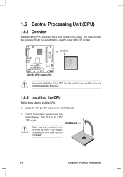
... CPU does not fit in one corner. 1.6 Central Processing Unit (CPU) 1.6.1 Overview The AMD Athlon™ 64 processor has a gold triangle in completely. Gold Arrow R K8V-MX K8V-MX CPU Socket 754 Incorrect installation of the CPU socket. This mark indicates the processor Pin A1 that the socket lever is lifted up to install... and severely damage the CPU! 1.6.2 Installing the CPU Follow these steps to a 90° -100° angle. Locate the 754-pin ZIF socket on the motherboard. 2.
... CPU does not fit in one corner. 1.6 Central Processing Unit (CPU) 1.6.1 Overview The AMD Athlon™ 64 processor has a gold triangle in completely. Gold Arrow R K8V-MX K8V-MX CPU Socket 754 Incorrect installation of the CPU socket. This mark indicates the processor Pin A1 that the socket lever is lifted up to install... and severely damage the CPU! 1.6.2 Installing the CPU Follow these steps to a 90° -100° angle. Locate the 754-pin ZIF socket on the motherboard. 2.
K8V-MX User's Manual for English Edition
Page 19
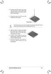
... above the socket such that the CPU corner with the gold triangle matches the socket corner with the heatsink package. 7. The lever clicks on the motherboard. Gold triangle The CPU fits only in place. C o n n e c t t h e C P U f a n c a b l e t o the CPU_FAN connector on the side tab to indicate that came with a small triangle. 4. 3. I n s t a l l a C P U h e a t s..., push down the socket lever to prevent bending the pins and damaging the CPU! 5. ASUS K8V-MX Motherboard 1-9 Carefully insert the CPU into the socket to secure the CPU. When the CPU is locked. 6.
... above the socket such that the CPU corner with the gold triangle matches the socket corner with the heatsink package. 7. The lever clicks on the motherboard. Gold triangle The CPU fits only in place. C o n n e c t t h e C P U f a n c a b l e t o the CPU_FAN connector on the side tab to indicate that came with a small triangle. 4. 3. I n s t a l l a C P U h e a t s..., push down the socket lever to prevent bending the pins and damaging the CPU! 5. ASUS K8V-MX Motherboard 1-9 Carefully insert the CPU into the socket to secure the CPU. When the CPU is locked. 6.
K8V-MX User's Manual for English Edition
Page 20
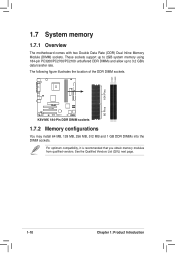
... List (QVL) next page. 80 Pins 1-10 Chapter 1: Product Introduction DIMM1 DIMM2 104 Pins 1.7 System memory 1.7.1 Overview The motherboard comes with two Double Data Rate (DDR) Dual Inline Memory Module (DIMM) sockets. R K8V-MX K8V-MX 184-Pin DDR DIMM sockets 1.7.2 Memory configurations You may install 64 MB, 128 MB, 256 MB, 512...
... List (QVL) next page. 80 Pins 1-10 Chapter 1: Product Introduction DIMM1 DIMM2 104 Pins 1.7 System memory 1.7.1 Overview The motherboard comes with two Double Data Rate (DDR) Dual Inline Memory Module (DIMM) sockets. R K8V-MX K8V-MX 184-Pin DDR DIMM sockets 1.7.2 Memory configurations You may install 64 MB, 128 MB, 256 MB, 512...
K8V-MX User's Manual for English Edition
Page 21
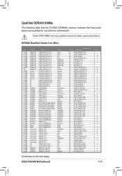
... SAMSUNG Winbond Winbond Winbond Winbond Elpida Elpida SAMSUNG Mosel PSC PSC Mosel SAMSUNG PSC Hynix Pmi Pmi Mosel Hynix KINGMAX (Continued on the next page) ASUS K8V-MX Motherboard DIMM support Side(s) Component SS HY5DU56822BT-D43 DS HY5DU56822BT-D43 SS A2S56D30BTP SS HY5DU12822BT-D43 SS D3208DL3T-5A DS D3208DH1T-5 SS D3208DH1T-6 DS D3208DH1T-6 DS... that have been tested and qualified for better system performance. Obtain DDR DIMMs only from qualified vendors for use with this motherboard.
... SAMSUNG Winbond Winbond Winbond Winbond Elpida Elpida SAMSUNG Mosel PSC PSC Mosel SAMSUNG PSC Hynix Pmi Pmi Mosel Hynix KINGMAX (Continued on the next page) ASUS K8V-MX Motherboard DIMM support Side(s) Component SS HY5DU56822BT-D43 DS HY5DU56822BT-D43 SS A2S56D30BTP SS HY5DU12822BT-D43 SS D3208DL3T-5A DS D3208DH1T-5 SS D3208DH1T-6 DS D3208DH1T-6 DS... that have been tested and qualified for better system performance. Obtain DDR DIMMs only from qualified vendors for use with this motherboard.
K8V-MX User's Manual for English Edition
Page 23
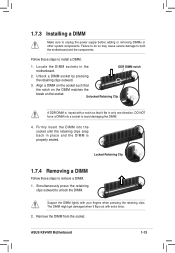
... a DIMM. 1. Locked Retaining Clip 1.7.4 Removing a DIMM Follow these steps to remove a DIMM. 1. Support the DIMM lightly with extra force. 2. Locate the DIMM sockets in the motherboard. ASUS K8V-MX Motherboard 1-13 DO NOT force a DIMM into the socket until the retaining clips snap back in only one direction. The DIMM might get damaged when it...
... a DIMM. 1. Locked Retaining Clip 1.7.4 Removing a DIMM Follow these steps to remove a DIMM. 1. Support the DIMM lightly with extra force. 2. Locate the DIMM sockets in the motherboard. ASUS K8V-MX Motherboard 1-13 DO NOT force a DIMM into the socket until the retaining clips snap back in only one direction. The DIMM might get damaged when it...

K8V-MX User's Manual for English Edition
Page 24
...Failure to do so may need to install an expansion card. 1. Remove the bracket opposite the slot that you physical injury and damage motherboard components. 1.8.1 Installing an expansion card Follow these steps to install expansion cards. Install the software drivers for information on the next page. ...Secure the card to the chassis with it and make the necessary hardware settings for later use . Remove the system unit cover (if your motherboard is completely seated on the system and change the necessary BIOS settings, if any. See Chapter 2 for the expansion card. 1-14 Chapter 1:...
...Failure to do so may need to install an expansion card. 1. Remove the bracket opposite the slot that you physical injury and damage motherboard components. 1.8.1 Installing an expansion card Follow these steps to install expansion cards. Install the software drivers for information on the next page. ...Secure the card to the chassis with it and make the necessary hardware settings for later use . Remove the system unit cover (if your motherboard is completely seated on the system and change the necessary BIOS settings, if any. See Chapter 2 for the expansion card. 1-14 Chapter 1:...
K8V-MX User's Manual for English Edition
Page 25
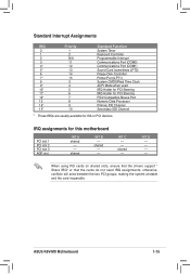
... PCI cards on shared slots, ensure that the drivers support " Share IRQ" or that the cards do not need IRQ assignments; shared INT B -- shared -- -- INT D -- -- -- -- ASUS K8V-MX Motherboard 1-15 Standard Interrupt Assignments IRQ Priority 0 1 1 2 2 N/A 3 11 4* 12 5* 13 6 14 7* 15 8 3 9* 4 10* 5 11* 6 12* 7 13 8 14* 9 15* 10 Standard... Compatible Mouse Port Numeric Data Processor Primary IDE Channel Secondary IDE Channel * These IRQs are usually available for this motherboard PCI slot 1 PCI slot 2 PCI slot 3 AGP slot INT A shared -- --
... PCI cards on shared slots, ensure that the drivers support " Share IRQ" or that the cards do not need IRQ assignments; shared INT B -- shared -- -- INT D -- -- -- -- ASUS K8V-MX Motherboard 1-15 Standard Interrupt Assignments IRQ Priority 0 1 1 2 2 N/A 3 11 4* 12 5* 13 6 14 7* 15 8 3 9* 4 10* 5 11* 6 12* 7 13 8 14* 9 15* 10 Standard... Compatible Mouse Port Numeric Data Processor Primary IDE Channel Secondary IDE Channel * These IRQs are usually available for this motherboard PCI slot 1 PCI slot 2 PCI slot 3 AGP slot INT A shared -- --
K8V-MX User's Manual for English Edition
Page 26
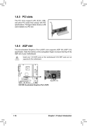
The figure below shows a LAN card installed on this motherboard! 3.3V AGP cards are not supported in this motherboard. Install only 1.5V AGP cards on a PCI slot. 1.8.4 AGP slot The Accelerated Graphics Port (AGP) slot supports AGP 8X (AGP 3.0) specifi...The PCI slots support LAN, SCSI, USB, and other PCI cards that they fit the AGP slot on your motherboard. Note the notches on the card golden fingers to ensure that comply with PCI specifications. R K8V-MX Keyed for 1.5v K8V-MX Accelerated Graphics Port (AGP) 1-16 Chapter 1: Product Introduction
The figure below shows a LAN card installed on this motherboard! 3.3V AGP cards are not supported in this motherboard. Install only 1.5V AGP cards on a PCI slot. 1.8.4 AGP slot The Accelerated Graphics Port (AGP) slot supports AGP 8X (AGP 3.0) specifi...The PCI slots support LAN, SCSI, USB, and other PCI cards that they fit the AGP slot on your motherboard. Note the notches on the card golden fingers to ensure that comply with PCI specifications. R K8V-MX Keyed for 1.5v K8V-MX Accelerated Graphics Port (AGP) 1-16 Chapter 1: Product Introduction
K8V-MX User's Manual for English Edition
Page 27
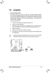
... position. 1.9 Jumpers 1. Plug the power cord and turn ON the computer. 6. Hold down the key during the boot process and enter BIOS setup to pins 1-2. 4. R K8V-MX K8V-MX Clear RTC RAM CLRTC 12 23 Normal (Default) Clear CMOS ASUS K8V-MX Motherboard 1-17
... position. 1.9 Jumpers 1. Plug the power cord and turn ON the computer. 6. Hold down the key during the boot process and enter BIOS setup to pins 1-2. 4. R K8V-MX K8V-MX Clear RTC RAM CLRTC 12 23 Normal (Default) Clear CMOS ASUS K8V-MX Motherboard 1-17
K8V-MX User's Manual for English Edition
Page 29
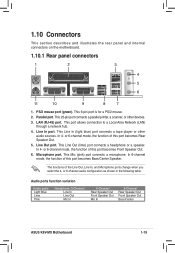
... Line In Line Out Mic In 4-Channel Rear Speaker Out Front Speaker Out Mic In 6-Channel Rear Speaker Out Front Speaker Out Bass/Center ASUS K8V-MX Motherboard 1-19 This 6-pin port is for a PS/2 mouse. 2. This Line In (light blue) port connects a tape player or other ...figuration as shown in the following table. In 4- In 4- 1.10 Connectors This section describes and illustrates the rear panel and internal connectors on the motherboard. 1.10.1 Rear panel connectors 1 2 3 4 5 6 11 10 9 8 7 1. This 25-pin port connects a parallel printer, a scanner, or other audio...
... Line In Line Out Mic In 4-Channel Rear Speaker Out Front Speaker Out Mic In 6-Channel Rear Speaker Out Front Speaker Out Bass/Center ASUS K8V-MX Motherboard 1-19 This 6-pin port is for a PS/2 mouse. 2. This Line In (light blue) port connects a tape player or other ...figuration as shown in the following table. In 4- In 4- 1.10 Connectors This section describes and illustrates the rear panel and internal connectors on the motherboard. 1.10.1 Rear panel connectors 1 2 3 4 5 6 11 10 9 8 7 1. This 25-pin port connects a parallel printer, a scanner, or other audio...


