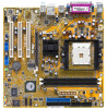
K8vmx Motherboard - Asus K8V MX
K8vmx Motherboard
Related Manual Pages

Related Videos

PC- MOTHERBOARD ASUS K8V-MX
Duration: 1:05
Total Views: 785
Duration: 1:05
Total Views: 785
Similar Questions

Motherboard Led Blinking
I have a problem with asus motherboard, when i power up i have notice that the Led blink on trhe mo...
I have a problem with asus motherboard, when i power up i have notice that the Led blink on trhe mo...
(Posted by deepsolutions 11 years ago)

Where Is My Model Number On My Motherboard?
Where is my model number on my motherboard?
Where is my model number on my motherboard?
(Posted by johnfiliceiiii 11 years ago)

No Display In The Monitor
How To Troubleshoot The Motherboard
no display in the monitor but when connected to another computer no problempls help me to troublesho...
no display in the monitor but when connected to another computer no problempls help me to troublesho...
(Posted by jersonsdnnn 11 years ago)

Where Do I Find A Motherboard Manual?
I need the manual for an Asus M3A78-EMH HDMI Socket AM2+AMD 780G/Hybrid CrossFireX/HDMI/A&V&...
I need the manual for an Asus M3A78-EMH HDMI Socket AM2+AMD 780G/Hybrid CrossFireX/HDMI/A&V&...
(Posted by ke7hhw 12 years ago)
Related Terms
The following terms were also used when searching for K8vmx Motherboard - Asus K8V MX:- asus k8v manual
- asus k8v memory
- asus k8v motherboard
- asus k8v mx
- asus k8v mx 754
- asus k8v mx audio driver
- asus k8v mx bios
- asus k8v mx bios update
- asus k8v mx display driver
- asus k8v mx driver
- asus k8v mx driver download
- asus k8v mx drivers
- asus k8v mx drivers download
- asus k8v mx drivers for windows vista
- asus k8v mx drivers for xp
- asus k8v mx drivers for xp download
- asus k8v mx drivers windows 7
- asus k8v mx k8m800
- asus k8v mx manual
- asus k8v mx motherboard
- asus k8v mx motherboard drivers
- asus k8v mx motherboard drivers for windows 7
- asus k8v mx motherboard drivers for windows xp
- asus k8v mx motherboard drivers free download
- asus k8v mx motherboard manual
- asus k8v mx motherboard specs
- asus k8v mx motherboard support cd
- asus k8v mx raid drivers
- asus k8v mx ram
- asus k8v mx s drivers
- asus k8v mx s manual
- asus k8v mx s motherboard
- asus k8v mx s video drivers
- asus k8v mx sound driver
- asus k8v mx specifications
- asus k8v mx vga driver
- asus k8v mx vista drivers
- asus k8v mx windows 7 drivers
- asus k8v-mx
- asus k8v-mx 754
- asus k8v-mx 754 via k8m800
- asus k8v-mx audio driver
- asus k8v-mx audio driver download
- asus k8v-mx audio driver for vista
- asus k8v-mx audio drivers
- asus k8v-mx audio drivers for windows 7
- asus k8v-mx audio drivers for xp
- asus k8v-mx bios
- asus k8v-mx bios download
- asus k8v-mx bios recovery
- asus k8v-mx bios update
- asus k8v-mx bios update download
- asus k8v-mx cpu
- asus k8v-mx cpu fan
- asus k8v-mx cpu fan replacement
- asus k8v-mx driver
- asus k8v-mx driver download
- asus k8v-mx driver for xp
- asus k8v-mx drivers
- asus k8v-mx drivers download
- asus k8v-mx drivers for windows 7
- asus k8v-mx drivers for xp
- asus k8v-mx drivers for xp download
- asus k8v-mx drivers free download
- asus k8v-mx drivers windows 7
- asus k8v-mx drivers xp
- asus k8v-mx front panel connections
- asus k8v-mx graphics card
- asus k8v-mx k8m800
- asus k8v-mx lan driver
- asus k8v-mx manual
- asus k8v-mx max ram
- asus k8v-mx memory
- asus k8v-mx memory compatibility
- asus k8v-mx motherboard
- asus k8v-mx motherboard bios update
- asus k8v-mx motherboard drivers
- asus k8v-mx motherboard drivers download
- asus k8v-mx motherboard drivers for windows 7
- asus k8v-mx motherboard drivers for xp
- asus k8v-mx motherboard drivers free download
- asus k8v-mx motherboard drivers windows 7
- asus k8v-mx motherboard manual
- asus k8v-mx motherboard manual download
- asus k8v-mx motherboard specification
- asus k8v-mx motherboard specs
- asus k8v-mx network driver
- asus k8v-mx processor support
- asus k8v-mx ram
- asus k8v-mx rev 3 drivers
- asus k8v-mx s audio
- asus k8v-mx s drivers
- asus k8v-mx s manual
- asus k8v-mx socket 754
- asus k8v-mx socket 754 motherboard
- asus k8v-mx sound driver
- asus k8v-mx specifications
- asus k8v-mx supported ram
- asus k8v-mx update bios
- asus k8v-mx vga driver
- asus k8v-mx vga driver download
- asus k8v-mx video drivers
- asus k8v-mx windows 7 driver downloads
- asus k8v-mx windows 7 drivers
- asus k8v-mx/s audio driver
- asus k8v-mx/s drivers
- asus k8v-mx/s manual
- asus k8v-mx/s motherboard
- asus k8v-mx/s motherboard manual
- asus k8v-mx/s schematics
- asus motherboard k8v mx
- k8v manual
- k8v memory
- k8v motherboard
- k8v mx
- k8v mx 754
- k8v mx asus
- k8v mx audio driver
- k8v mx audio drivers
- k8v mx bios
- k8v mx bios update
- k8v mx cpu support
- k8v mx display driver
- k8v mx driver
- k8v mx driver download
- k8v mx drivers
- k8v mx drivers download
- k8v mx drivers for windows 7
- k8v mx drivers for windows vista
- k8v mx drivers for xp
- k8v mx drivers for xp download
- k8v mx drivers free download
- k8v mx drivers windows 7
- k8v mx k8m800
- k8v mx manual
- k8v mx motherboard
- k8v mx motherboard drivers
- k8v mx motherboard drivers for windows 7
- k8v mx motherboard drivers for windows xp
- k8v mx motherboard drivers free download
- k8v mx motherboard manual
- k8v mx motherboard specs
- k8v mx motherboard support cd
- k8v mx raid drivers
- k8v mx ram
- k8v mx rom
- k8v mx s bios
- k8v mx s drivers
- k8v mx s manual
- k8v mx s motherboard
- k8v mx s motherboard manual
- k8v mx s video drivers
- k8v mx sound driver
- k8v mx specifications
- k8v mx vga driver
- k8v mx vista drivers
- k8v mx windows 7
- k8v mx windows 7 drivers
- k8v mx windows 7 no sound
- k8v-mx
- k8v-mx 754
- k8v-mx 754 via k8m800
- k8v-mx asus
- k8v-mx asus motherboard drivers
- k8v-mx asus motherboard software & drivers
- k8v-mx audio driver
- k8v-mx audio driver download
- k8v-mx audio driver for vista
- k8v-mx audio driver for xp
- k8v-mx audio drivers
- k8v-mx audio drivers for windows 7
- k8v-mx audio drivers for xp
- k8v-mx bios
- k8v-mx bios download
- k8v-mx bios recovery
- k8v-mx bios update
- k8v-mx bios update download
- k8v-mx cpu
- k8v-mx cpu fan
- k8v-mx cpu fan replacement
- k8v-mx cpu support
- k8v-mx display driver
- k8v-mx driver
- k8v-mx driver cd
- k8v-mx driver download
- k8v-mx driver for xp
- k8v-mx drivers
- k8v-mx drivers download
- k8v-mx drivers for windows 7
- k8v-mx drivers for windows vista
- k8v-mx drivers for windows xp
- k8v-mx drivers for xp
- k8v-mx drivers for xp download
- k8v-mx drivers free download
- k8v-mx drivers per windows 7
- k8v-mx drivers windows 7
- k8v-mx drivers xp
- k8v-mx front panel connections
- k8v-mx graphic driver
- k8v-mx graphic driver for windows vista
- k8v-mx graphics card
- k8v-mx k8m800
- k8v-mx lan driver
- k8v-mx lan drivers
- k8v-mx manual
- k8v-mx manual pdf
- k8v-mx max ram
- k8v-mx memory
- k8v-mx memory compatibility
- k8v-mx memory support
- k8v-mx motherboard
- k8v-mx motherboard bios update
- k8v-mx motherboard driver download
- k8v-mx motherboard drivers
- k8v-mx motherboard drivers download
- k8v-mx motherboard drivers for windows 7
- k8v-mx motherboard drivers for xp
- k8v-mx motherboard drivers free download
- k8v-mx motherboard drivers windows 7
- k8v-mx motherboard manual
- k8v-mx motherboard manual download
- k8v-mx motherboard specification
- k8v-mx motherboard specs
- k8v-mx network driver
- k8v-mx processor
- k8v-mx processor support
- k8v-mx ram
- k8v-mx rev 3 drivers
- k8v-mx s audio
- k8v-mx s audio driver
- k8v-mx s drivers
- k8v-mx s manual
- k8v-mx s motherboard
- k8v-mx s motherboard manual
- k8v-mx sata
- k8v-mx socket 754
- k8v-mx socket 754 motherboard
- k8v-mx sound driver
- k8v-mx sound driver for windows 7
- k8v-mx specifications
- k8v-mx supported processors
- k8v-mx supported ram
- k8v-mx update bios
- k8v-mx updates
- k8v-mx vga driver
- k8v-mx vga driver download
- k8v-mx video driver
- k8v-mx video drivers
- k8v-mx windows 7
- k8v-mx windows 7 driver downloads
- k8v-mx windows 7 drivers
- k8v-mx-uaykz
- k8v-mx.rom
- k8v-mx/s audio driver
- k8v-mx/s bios
- k8v-mx/s driver
- k8v-mx/s drivers
- k8v-mx/s drivers audio
- k8v-mx/s manual
- k8v-mx/s motherboard
- k8v-mx/s motherboard manual
- k8v-mx/s schematics
- k8v-mx/s sound
- k8v-x drivers
- k8v-x lan drivers
- k8vmx asus drivers
- k8vmx asus motherboard drivers
- k8vmx audio driver
- k8vmx bios
- k8vmx bios update
- k8vmx display driver download
- k8vmx display drivers
- k8vmx driver for windows 7
- k8vmx drivers
- k8vmx manual
- k8vmx motherboard
- k8vmx motherboard drivers
- k8vmx motherboard drivers download
- k8vmx motherboard manual
- k8vmx motherboard specs
- k8vmx motherboards
- k8vmx ram
- k8vmx s manual
- k8vmx sata drivers
- k8vmx series
- k8vmx sound driver
- k8vmx sound drivers
- k8vmx vga asus driver
- k8vmx vga driver
- k8vmx. com
- k8vmx.rom
- k8vmx/s drivers