
User Guide
Page 10
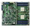
...ATX 12 V 2.0 compliant (continued on board; RAID 0, RAID 1, RAID 1+0, and JBOD configurations LSI 1020A SCSI RAID controller supports: - RAID 0, RAID 1, and RAID 1E configurations (SCSI model only) Dual LAN 2 x BROADCOM® BCM5721 Gigabit PCI-E LAN controllers USB 2 x USB 2.0 ports (on the rear panel) 1 x USB 2.0 connector (on the next page) x K8N-DRE.../266 MHz DDR memory modules Supports up to 32 GB system memory (Note: Tested only up to 16 GB on this motherboard due to 2 GB DDR availability) 1 x PCI Express x16 slot 1 x PCI slot NVIDIA® nForce Professional 2200 chipset...
...ATX 12 V 2.0 compliant (continued on board; RAID 0, RAID 1, RAID 1+0, and JBOD configurations LSI 1020A SCSI RAID controller supports: - RAID 0, RAID 1, and RAID 1E configurations (SCSI model only) Dual LAN 2 x BROADCOM® BCM5721 Gigabit PCI-E LAN controllers USB 2 x USB 2.0 ports (on the rear panel) 1 x USB 2.0 connector (on the next page) x K8N-DRE.../266 MHz DDR memory modules Supports up to 32 GB system memory (Note: Tested only up to 16 GB on this motherboard due to 2 GB DDR availability) 1 x PCI Express x16 slot 1 x PCI slot NVIDIA® nForce Professional 2200 chipset...
User Guide
Page 16
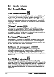
PCI Express™ interface The motherboard fully supports PCI Express, the latest I/O interconnect technology that speeds up to increase the communication speed between devices and allows higher clockspeeds by carrying data in packets. The SATA 3Gb/s specification provides twice the bandwidth...See page 2-12. Additionally, Serial ATA allows thinner, more flexible cables with existing PCI specifications. Serial ATA 3Gb/s technology The motherboard supports the next-generation Serial ATA 3Gb/s technology through the Serial ATA interfaces and the NVIDIA® nForce4® PRO chipset....
PCI Express™ interface The motherboard fully supports PCI Express, the latest I/O interconnect technology that speeds up to increase the communication speed between devices and allows higher clockspeeds by carrying data in packets. The SATA 3Gb/s specification provides twice the bandwidth...See page 2-12. Additionally, Serial ATA allows thinner, more flexible cables with existing PCI specifications. Serial ATA 3Gb/s technology The motherboard supports the next-generation Serial ATA 3Gb/s technology through the Serial ATA interfaces and the NVIDIA® nForce4® PRO chipset....

User Guide
Page 17
See pages 2-23 and 2-24 for four SATA and two PATA connectors. The LSI 1020A controller (SCSI models only) supports a single-channel SCSI Ultra320 and allows RAID 0, RAID 1, and RAID 1E. USB 2.0 is ... 4-27. ASUS K8N-DRE 1-3 The NVIDIA® nForce4® PRO allows RAID 0, RAID 1, RAID 0+1 and JBOD configuration for details. See pages 2-25 for details. Temperature, fan, and voltage monitoring The CPU temperature is monitored by the ASIC (Winbond W83792D) to ensure stable supply of current for timely failure detection. USB 2.0 technology The motherboard implements...
See pages 2-23 and 2-24 for four SATA and two PATA connectors. The LSI 1020A controller (SCSI models only) supports a single-channel SCSI Ultra320 and allows RAID 0, RAID 1, and RAID 1E. USB 2.0 is ... 4-27. ASUS K8N-DRE 1-3 The NVIDIA® nForce4® PRO allows RAID 0, RAID 1, RAID 0+1 and JBOD configuration for details. See pages 2-25 for details. Temperature, fan, and voltage monitoring The CPU temperature is monitored by the ASIC (Winbond W83792D) to ensure stable supply of current for timely failure detection. USB 2.0 technology The motherboard implements...
User Guide
Page 44
... 0, RAID 1, RAID 1+0, or JBOD configuration. 3. SATA2 GND RSATA_TXP2 RSATA_TXN2 GND RSATA_RXN2 RSATA_RXP2 GND GND RSATA_TXP1 RSATA_TXN1 GND RSATA_RXN1 RSATA_RXP1 GND K8N-DRE ® SATA1 SATA4 GND RSATA_TXP4 RSATA_TXN4 GND RSATA_RXN4 RSATA_RXP4 GND K8N-DRE SATA connectors SATA3 GND RSATA_TXP3 RSATA_TXN3 GND RSATA_RXN3 RSATA_RXP3 GND Important notes on Serial ATA The actual data transfer rate depends...
... 0, RAID 1, RAID 1+0, or JBOD configuration. 3. SATA2 GND RSATA_TXP2 RSATA_TXN2 GND RSATA_RXN2 RSATA_RXP2 GND GND RSATA_TXP1 RSATA_TXN1 GND RSATA_RXN1 RSATA_RXP1 GND K8N-DRE ® SATA1 SATA4 GND RSATA_TXP4 RSATA_TXN4 GND RSATA_RXN4 RSATA_RXP4 GND K8N-DRE SATA connectors SATA3 GND RSATA_TXP3 RSATA_TXN3 GND RSATA_RXN3 RSATA_RXP3 GND Important notes on Serial ATA The actual data transfer rate depends...

User Guide
Page 45
...K8N-DRE Hard disk activity LED connector ASUS K8N-DRE 2-25 When an SE device is for SCSI model only) This 68-pin Ultra160/320 SCSI connector supports a maximum of 12m (or 25m in a point-to an SE speed and 1.5m cable length. 5 . p i n S C S I 1 ) (for the storage add-on card cable connected to the SCSI or SATA... add-on card causes the front panel LED to light up to 160MB/s or 320MB/s) and extended cabling of 15 devices as specified by the Ultra160/320 standards. 4 . The read or write activities of...
...K8N-DRE Hard disk activity LED connector ASUS K8N-DRE 2-25 When an SE device is for SCSI model only) This 68-pin Ultra160/320 SCSI connector supports a maximum of 12m (or 25m in a point-to an SE speed and 1.5m cable length. 5 . p i n S C S I 1 ) (for the storage add-on card cable connected to the SCSI or SATA... add-on card causes the front panel LED to light up to 160MB/s or 320MB/s) and extended cabling of 15 devices as specified by the Ultra160/320 standards. 4 . The read or write activities of...

User Guide
Page 51
... up when you to this connector. The speaker allows you turn on the BIOS settings. ASUS K8N-DRE 2-31 POWERBTN# NC GND +5V NC GND RESETBTN# GND GND SPKROUT K8N-DRE System panel connector The system panel connector is for easy connection. Connect the chassis power LED... warning speaker (Orange 4-pin SPKROUT) This 4-pin connector is for the chassis-mounted system warning speaker. K8N-DRE PANEL1 ® HDLED+ POWERLED+ HDLED- If an optional SCSI or SATA add-in card causes this LED to this connector. 14. Pressing the power switch for more than four...
... up when you to this connector. The speaker allows you turn on the BIOS settings. ASUS K8N-DRE 2-31 POWERBTN# NC GND +5V NC GND RESETBTN# GND GND SPKROUT K8N-DRE System panel connector The system panel connector is for easy connection. Connect the chassis power LED... warning speaker (Orange 4-pin SPKROUT) This 4-pin connector is for the chassis-mounted system warning speaker. K8N-DRE PANEL1 ® HDLED+ POWERLED+ HDLED- If an optional SCSI or SATA add-in card causes this LED to this connector. 14. Pressing the power switch for more than four...

User Guide
Page 99
5.1 Setting up RAID The motherboard comes with the following RAID solutions: • The N V I D I A® nForce Professional 2200 chipset comes with a built-in SATA RAID controller that allows you to configure RAID 0, RAID 1, RAID 1+0 and JBOD with each stripe unit having a secondary (or alternate) ...hard disk drives to read and write data in a created RAID set . This configuration stores the same data redundantly on the operating system. ASUS K8N-DRE 5-1 Two hard disks perform the same work as a single drive but at a sustained data transfer rate, double that are striped together. ...
5.1 Setting up RAID The motherboard comes with the following RAID solutions: • The N V I D I A® nForce Professional 2200 chipset comes with a built-in SATA RAID controller that allows you to configure RAID 0, RAID 1, RAID 1+0 and JBOD with each stripe unit having a secondary (or alternate) ...hard disk drives to read and write data in a created RAID set . This configuration stores the same data redundantly on the operating system. ASUS K8N-DRE 5-1 Two hard disks perform the same work as a single drive but at a sustained data transfer rate, double that are striped together. ...

User Guide
Page 100
... at the back of the SCSI interface cable to the IDE and/or SATA connectors supported by the NVIDIA® nForce Professional 2200 chip. For optimal performance, install identical drives of each drive and to the SATA connector on the motherboard. 5.1.3 RAID configuration utility You can use the N V I D I A®... R A I D U t i l i t y if you installed IDE and/or SATA hard disk drives to the SCSI connector on the motherboard. 3. Connect a SATA power cable to the ...
... at the back of the SCSI interface cable to the IDE and/or SATA connectors supported by the NVIDIA® nForce Professional 2200 chip. For optimal performance, install identical drives of each drive and to the SATA connector on the motherboard. 5.1.3 RAID configuration utility You can use the N V I D I A®... R A I D U t i l i t y if you installed IDE and/or SATA hard disk drives to the SCSI connector on the motherboard. 3. Connect a SATA power cable to the ...

User Guide
Page 101
... to set the BIOS RAID items: 1. Set the R A I D E C o n f i g u r a t i o n, then press . 3. 5.2 NVIDIA® RAID configurations The motherboard includes a high performance SATA RAID controller integrated in the BIOS before setting your screen. Enter the BIOS Setup during POST. 2. ASUS K8N-DRE 5-3 Enable the drives you want to Chapter 4 for details on entering and navigating through the BIOS...
... to set the BIOS RAID items: 1. Set the R A I D E C o n f i g u r a t i o n, then press . 3. 5.2 NVIDIA® RAID configurations The motherboard includes a high performance SATA RAID controller integrated in the BIOS before setting your screen. Enter the BIOS Setup during POST. 2. ASUS K8N-DRE 5-3 Enable the drives you want to Chapter 4 for details on entering and navigating through the BIOS...

User Guide
Page 109
Turn on the system after installing all the SATA hard disk drives. 2. During POST, Press + to the next section for details. ASUS K8N-DRE 5-11 The LSI Logic Configuration Utility main menu appears. The LSI Logic Configuration Utility has two tabbed menus that you to create RAID 0, RAID 1, and ...
Turn on the system after installing all the SATA hard disk drives. 2. During POST, Press + to the next section for details. ASUS K8N-DRE 5-11 The LSI Logic Configuration Utility main menu appears. The LSI Logic Configuration Utility has two tabbed menus that you to create RAID 0, RAID 1, and ...
User Guide
Page 132
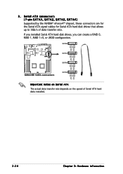
... or RAID driver. 2. To create a RAID driver disk in the optical drive. 2. Press , then insert the RAID driver disk to create an NVIDIA nForce(TM) SATA RAID driver disk for a 32-bit Windows 2000/2003 system, press , then press . 7. Place the motherboard support CD in Windows®: 1.
... or RAID driver. 2. To create a RAID driver disk in the optical drive. 2. Press , then insert the RAID driver disk to create an NVIDIA nForce(TM) SATA RAID driver disk for a 32-bit Windows 2000/2003 system, press , then press . 7. Place the motherboard support CD in Windows®: 1.


