CUW-RM User Manual
Page 1
® CUW-RM Intel® 810 microATX Motherboard USER'S MANUAL
® CUW-RM Intel® 810 microATX Motherboard USER'S MANUAL
CUW-RM User Manual
Page 4
... Configuration 62 4.4.2 I/O Device Configuration 64 4.4.3 PCI Configuration 66 4.4.4 Shadow Configuration 69 4 ASUS CUW-RM User's Manual FEATURES 8 2.1 The ASUS CUW-RM Motherboard 8 2.1.1 Specifications 8 2.1.2 Optional Components 9 2.1.3 Performance 10 2.1.4 Intelligence 11 2.2 Features and Component Locations 12 3. HARDWARE SETUP 14 3.1 Motherboard Layout 14 3.2 Layout Contents 15 3.3 Hardware Setup Procedure 17 3.4 Motherboard Settings 17 3.5 System Memory (DIMM 24 3.5.1 General DIMM Notes 24 3.5.2 Memory...
... Configuration 62 4.4.2 I/O Device Configuration 64 4.4.3 PCI Configuration 66 4.4.4 Shadow Configuration 69 4 ASUS CUW-RM User's Manual FEATURES 8 2.1 The ASUS CUW-RM Motherboard 8 2.1.1 Specifications 8 2.1.2 Optional Components 9 2.1.3 Performance 10 2.1.4 Intelligence 11 2.2 Features and Component Locations 12 3. HARDWARE SETUP 14 3.1 Motherboard Layout 14 3.2 Layout Contents 15 3.3 Hardware Setup Procedure 17 3.4 Motherboard Settings 17 3.5 System Memory (DIMM 24 3.5.1 General DIMM Notes 24 3.5.2 Memory...
CUW-RM User Manual
Page 5
APPENDIX 113 7.1 PCI-L101 Fast Ethernet Card 113 7.2 Modem Riser 115 7.3 Glossary 117 ASUS CUW-RM User's Manual 5 SOFTWARE SETUP 79 5.1 Operating Systems 79 5.2 Starting Windows For the First Time 79 5.3 ASUS Smart Motherboard Support CD 81 5.4 INF Update Utility for 810 Chipset 82 5.5 VGA Driver Setup 83 5.6 Audio Driver Setup 84 5.7 Intel Security Driver 85...
APPENDIX 113 7.1 PCI-L101 Fast Ethernet Card 113 7.2 Modem Riser 115 7.3 Glossary 117 ASUS CUW-RM User's Manual 5 SOFTWARE SETUP 79 5.1 Operating Systems 79 5.2 Starting Windows For the First Time 79 5.3 ASUS Smart Motherboard Support CD 81 5.4 INF Update Utility for 810 Chipset 82 5.5 VGA Driver Setup 83 5.6 Audio Driver Setup 84 5.7 Intel Security Driver 85...
CUW-RM User Manual
Page 7
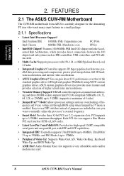
1. INTRODUCTION Sections/Checklist 1. If you discover damaged or missing items, please contact your retailer. (1) ASUS Motherboard (1) 40-pin 80-conductor ribbon cable for internal UltraDMA/66 or UltraDMA/ 33 IDE drives (1) Ribbon cable ...motherboard 4) BIOS SETUP Instructions on setting up the BIOS software 5) SOFTWARE SETUP Instructions on setting up the included software 6) SOFTWARE REFERENCE Reference material for LCD model only) ASUS IrDA-compliant infrared module (optional) ASUS consumer infrared set (optional) ASUS PCI-L101 Wake-On-LAN 10/100 ethernet card (optional) ASUS CUW-RM...
1. INTRODUCTION Sections/Checklist 1. If you discover damaged or missing items, please contact your retailer. (1) ASUS Motherboard (1) 40-pin 80-conductor ribbon cable for internal UltraDMA/66 or UltraDMA/ 33 IDE drives (1) Ribbon cable ...motherboard 4) BIOS SETUP Instructions on setting up the BIOS software 5) SOFTWARE SETUP Instructions on setting up the included software 6) SOFTWARE REFERENCE Reference material for LCD model only) ASUS IrDA-compliant infrared module (optional) ASUS consumer infrared set (optional) ASUS PCI-L101 Wake-On-LAN 10/100 ethernet card (optional) ASUS CUW-RM...
CUW-RM User Manual
Page 8
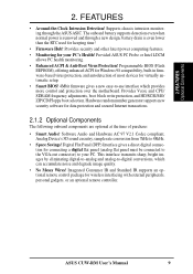
... Slot! Audio Modem Riser slot supports a very affordable audio and/or modem riser card. 8 ASUS CUW-RM User's Manual ASUS custom graphics driver also provides more features and provides selection of 4 sides) • JumperFree™...processing and compression, precise pixel interpolation, full 2D hardware acceleration, and motion video acceleration. • ASUS Graphics Driver! Provides three 32-bit PCI (rev 2.2) expansion slots. Controller supports UltraDMA/66 up ...8226; Integrated IDE! FEATURES 2.1 The ASUS CUW-RM Motherboard The CUW-RM motherboard from ASUS is enabled.
... Slot! Audio Modem Riser slot supports a very affordable audio and/or modem riser card. 8 ASUS CUW-RM User's Manual ASUS custom graphics driver also provides more features and provides selection of 4 sides) • JumperFree™...processing and compression, precise pixel interpolation, full 2D hardware acceleration, and motion video acceleration. • ASUS Graphics Driver! Provides three 32-bit PCI (rev 2.2) expansion slots. Controller supports UltraDMA/66 up ...8226; Integrated IDE! FEATURES 2.1 The ASUS CUW-RM Motherboard The CUW-RM motherboard from ASUS is enabled.
CUW-RM User Manual
Page 9
... provides more control and protection over the motherboard. Digital Flat Panel (DFP) Interface gives a direct digital connection for Windows 98 compatibility, built-in firmware-based virus protection, and autodetection of purchase: • Smart Audio! ASUS CUW-RM User's Manual 9 Supports chassis intrusion monitoring... through a new design, battery drain is even lower than the RTC used for your PC. Provided ASUS PC Probe or Intel LDCM allows PC health monitoring. ...
... provides more control and protection over the motherboard. Digital Flat Panel (DFP) Interface gives a direct digital connection for Windows 98 compatibility, built-in firmware-based virus protection, and autodetection of purchase: • Smart Audio! ASUS CUW-RM User's Manual 9 Supports chassis intrusion monitoring... through a new design, battery drain is even lower than the RTC used for your PC. Provided ASUS PC Probe or Intel LDCM allows PC health monitoring. ...

CUW-RM User Manual
Page 10
... ready around the clock, yet satisfy all system components, and 32-bit device drivers and installation procedures for an exciting gameplay experience. 10 ASUS CUW-RM User's Manual ASUS smart series motherboards support the new generation memory, Synchronous Dynamic Random Access Memory (SDRAM), which increases the data transfer rate to improve audio quality and performance...
... ready around the clock, yet satisfy all system components, and 32-bit device drivers and installation procedures for an exciting gameplay experience. 10 ASUS CUW-RM User's Manual ASUS smart series motherboards support the new generation memory, Synchronous Dynamic Random Access Memory (SDRAM), which increases the data transfer rate to improve audio quality and performance...
CUW-RM User Manual
Page 11
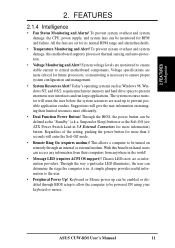
... button can be enabled or disabled through an internal or external modem. With this motherboard supports processor thermal sensing and auto-protection. • Voltage Monitoring and Alert! ASUS CUW-RM User's Manual 11 To prevent system overheat and system damage, the CPU, power supply...• Dual Function Power Button! Chassis LEDs now act as the "Standby" (a.k.a. A simple glimpse provides useful information to critical motherboard components. Through the way a particular LED illuminates, the user can be defined as information providers. Keyboard or Mouse power up to ...
... button can be enabled or disabled through an internal or external modem. With this motherboard supports processor thermal sensing and auto-protection. • Voltage Monitoring and Alert! ASUS CUW-RM User's Manual 11 To prevent system overheat and system damage, the CPU, power supply...• Dual Function Power Button! Chassis LEDs now act as the "Standby" (a.k.a. A simple glimpse provides useful information to critical motherboard components. Through the way a particular LED illuminates, the user can be defined as information providers. Keyboard or Mouse power up to ...
CUW-RM User Manual
Page 12
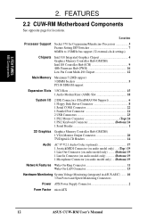
FEATURES 2.2 CUW-RM Motherboard Components See opposite page for Coppermine/Mendocino Processors 3 Feature Setting DIP Switches 7 66MHz to 150MHz bus support (32 external clock settings) Chipsets Intel...(Bottom) 19 Network Features Wake-On-Ring Connector 11 Wake-On-LAN Connector 13 Hardware Monitoring System Voltage Monitoring (integrated in ASUS ASIC) ....... 10 3 Fan Power and Speed Monitoring Connectors Power ATX Power Supply Connector 2 Form Factor microATX 12 ASUS CUW-RM User's Manual Location Processor Support Socket 370 for locations. FEATURES MB Components 2. 2.
FEATURES 2.2 CUW-RM Motherboard Components See opposite page for Coppermine/Mendocino Processors 3 Feature Setting DIP Switches 7 66MHz to 150MHz bus support (32 external clock settings) Chipsets Intel...(Bottom) 19 Network Features Wake-On-Ring Connector 11 Wake-On-LAN Connector 13 Hardware Monitoring System Voltage Monitoring (integrated in ASUS ASIC) ....... 10 3 Fan Power and Speed Monitoring Connectors Power ATX Power Supply Connector 2 Form Factor microATX 12 ASUS CUW-RM User's Manual Location Processor Support Socket 370 for locations. FEATURES MB Components 2. 2.
CUW-RM User Manual
Page 14
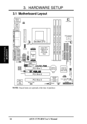
SAFE_MD NO_REBOOT IDELED 14 ASUS CUW-RM User's Manual HARDWARE SETUP 3.1 Motherboard Layout PS/2 T: Mouse B: Keyboard VIO USB T: Port1 B: Port2 COM1 ...I/O CD LCDTV1 TAD Audio Modem Riser (AMR) Intel 810 Graphics & Memory Controller Hub Audio Codec Setting CUW-RM Audio Codec PCI Slot 1 PCI3VSBSEL SPDO SPDI ® AUDIOEN PCI Slot 2 4Mbit Firmware Hub (FWH)... 2 3 3 2 CR2032 3V Lithium Cell CMOS Power Intel I/O Controller Hub (ICH) SMB ASUS ASIC Clear CMOS with Hardware Monitor (R191) ACHA WOR JTPWR PANEL NOTE: Grayed items are optional at the time of...
SAFE_MD NO_REBOOT IDELED 14 ASUS CUW-RM User's Manual HARDWARE SETUP 3.1 Motherboard Layout PS/2 T: Mouse B: Keyboard VIO USB T: Port1 B: Port2 COM1 ...I/O CD LCDTV1 TAD Audio Modem Riser (AMR) Intel 810 Graphics & Memory Controller Hub Audio Codec Setting CUW-RM Audio Codec PCI Slot 1 PCI3VSBSEL SPDO SPDI ® AUDIOEN PCI Slot 2 4Mbit Firmware Hub (FWH)... 2 3 3 2 CR2032 3V Lithium Cell CMOS Power Intel I/O Controller Hub (ICH) SMB ASUS ASIC Clear CMOS with Hardware Monitor (R191) ACHA WOR JTPWR PANEL NOTE: Grayed items are optional at the time of...
CUW-RM User Manual
Page 15
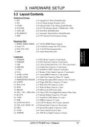
HARDWARE SETUP 3.2 Layout Contents Motherboard Settings 1) JEN 2) VIO 3) CODEC 4) PCI3VSEL 5) SAFE_MD 6) NO_REBOOT 7) DSW p.18 JumperFree™ Mode (Enable/Disable) p.18 I/O Voltage Setting (Normal/+3.66V) p.19 Onboard Audio Codec Setting (Enable/... (Four 4-pins) 20) MIC2 p.39 Internal Microphone Connector (3 pins) 21) ACHA p.40 Chassis Intrusion Lead (2-pins) 22) ATXPWR p.40 ATX Power Supply Connector (20 pins) ASUS CUW-RM User's Manual 15 3. H/W SETUP Layout Contents 3.
HARDWARE SETUP 3.2 Layout Contents Motherboard Settings 1) JEN 2) VIO 3) CODEC 4) PCI3VSEL 5) SAFE_MD 6) NO_REBOOT 7) DSW p.18 JumperFree™ Mode (Enable/Disable) p.18 I/O Voltage Setting (Normal/+3.66V) p.19 Onboard Audio Codec Setting (Enable/... (Four 4-pins) 20) MIC2 p.39 Internal Microphone Connector (3 pins) 21) ACHA p.40 Chassis Intrusion Lead (2-pins) 22) ATXPWR p.40 ATX Power Supply Connector (20 pins) ASUS CUW-RM User's Manual 15 3. H/W SETUP Layout Contents 3.
CUW-RM User Manual
Page 17
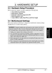
... components are separated from static electricity, you should follow some precautions whenever you do not have one, touch both of switches and/or jumpers. H/W SETUP Motherboard Settings ASUS CUW-RM User's Manual 17 HARDWARE SETUP 3.3 Hardware Setup Procedure Before using your computer, you must complete the following steps: • Check...
... components are separated from static electricity, you should follow some precautions whenever you do not have one, touch both of switches and/or jumpers. H/W SETUP Motherboard Settings ASUS CUW-RM User's Manual 17 HARDWARE SETUP 3.3 Hardware Setup Procedure Before using your computer, you must complete the following steps: • Check...
CUW-RM User Manual
Page 18
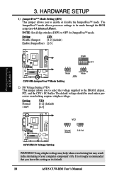
...mode allows processor settings to the DRAM, chipset, PCI, and the CPU's I/O buffer. H/W SETUP Motherboard Settings CUW-RM ® 123 DSW ON 12345 123 OFF Jumper Mode JumperFree Mode JEN CUW-RM JumperFree™ Mode Setting 2) I /O Voltage Setting WARNING! Using a higher voltage may help when... (Jumper) [1-2] (default) Enable (JumperFree) [2-3] 3. 3. It is strongly recommended that you leave this setting on its default. 18 ASUS CUW-RM User's Manual NOTE: Set all dip switches (DSW) to enable or disable the JumperFree™ mode. The default voltage should be made...
...mode allows processor settings to the DRAM, chipset, PCI, and the CPU's I/O buffer. H/W SETUP Motherboard Settings CUW-RM ® 123 DSW ON 12345 123 OFF Jumper Mode JumperFree Mode JEN CUW-RM JumperFree™ Mode Setting 2) I /O Voltage Setting WARNING! Using a higher voltage may help when... (Jumper) [1-2] (default) Enable (JumperFree) [2-3] 3. 3. It is strongly recommended that you leave this setting on its default. 18 ASUS CUW-RM User's Manual NOTE: Set all dip switches (DSW) to enable or disable the JumperFree™ mode. The default voltage should be made...
CUW-RM User Manual
Page 19
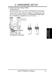
... expansion slots or a primary AMR on any of these jumpers. Setting Enable CODEC [1-2] [1-2] [1-2] [1-2] Disable [2-3] [2-3] [2-3] [2-3] SPK AUD_EN1 SPK AUD_EN1 ADN# AUD_EN2 CUW-RM ® CUW-RM Audio Codec Setting 3 3 2 2 1 1 ADN# AUD_EN2 Enable Disable 3. H/W SETUP Motherboard Settings ASUS CUW-RM User's Manual 19 If using a PCI audio card on the AMR slot (see AMR Slot later in 4.4.2 I/O Device Configuration must...
... expansion slots or a primary AMR on any of these jumpers. Setting Enable CODEC [1-2] [1-2] [1-2] [1-2] Disable [2-3] [2-3] [2-3] [2-3] SPK AUD_EN1 SPK AUD_EN1 ADN# AUD_EN2 CUW-RM ® CUW-RM Audio Codec Setting 3 3 2 2 1 1 ADN# AUD_EN2 Enable Disable 3. H/W SETUP Motherboard Settings ASUS CUW-RM User's Manual 19 If using a PCI audio card on the AMR slot (see AMR Slot later in 4.4.2 I/O Device Configuration must...
CUW-RM User Manual
Page 20
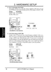
...jumper allows you have locked frequency multiples. In this case, there is possible through motherboard settings or BIOS setup. If this jumper to correct the problem. H/W SETUP Motherboard Settings CUW-RM ® CUW-RM PCI 3 Volt Selection PCI3VSBSEL 123 123 Enable 3 VSB Disable 3 VSB 5) ...enter BIOS setup to Enable 3 VSB. Setting Normal Safe Mode SAFE_MD [1-2] (default) [2-3] CUW-RM ® CUW-RM Safe Mode Setting SAFE_MD 3 2 1 Normal (Default) 3 2 1 Safe Mode 20 ASUS CUW-RM User's Manual With unlocked socket 370 processors, exceeding the specified multiple is no way to PCI...
...jumper allows you have locked frequency multiples. In this case, there is possible through motherboard settings or BIOS setup. If this jumper to correct the problem. H/W SETUP Motherboard Settings CUW-RM ® CUW-RM PCI 3 Volt Selection PCI3VSBSEL 123 123 Enable 3 VSB Disable 3 VSB 5) ...enter BIOS setup to Enable 3 VSB. Setting Normal Safe Mode SAFE_MD [1-2] (default) [2-3] CUW-RM ® CUW-RM Safe Mode Setting SAFE_MD 3 2 1 Normal (Default) 3 2 1 Safe Mode 20 ASUS CUW-RM User's Manual With unlocked socket 370 processors, exceeding the specified multiple is no way to PCI...

CUW-RM User Manual
Page 21
H/W SETUP Motherboard Settings ASUS CUW-RM User's Manual 21 If rebooting is set this jumper to No Reboot to disable auto-reboot. 3. Setting Normal No Reboot NO_REBOOT [1-2] (default) [2-3] CUW-RM ® CUW-RM Reboot Setting NO_REBOOT 3 2 1 Normal (Default) 3 2 1 No Reboot 3. HARDWARE SETUP 6) Automatic Timeout Reboot Setting (NO_REBOOT) The motherboard is repeating ineffectively, set so that when the BIOS detects a hang (timeout) during bootup, the motherboard will automatically reboot.
H/W SETUP Motherboard Settings ASUS CUW-RM User's Manual 21 If rebooting is set this jumper to No Reboot to disable auto-reboot. 3. Setting Normal No Reboot NO_REBOOT [1-2] (default) [2-3] CUW-RM ® CUW-RM Reboot Setting NO_REBOOT 3 2 1 Normal (Default) 3 2 1 No Reboot 3. HARDWARE SETUP 6) Automatic Timeout Reboot Setting (NO_REBOOT) The motherboard is repeating ineffectively, set so that when the BIOS detects a hang (timeout) during bootup, the motherboard will automatically reboot.
CUW-RM User Manual
Page 22
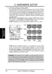
... sure that the DIMM you use can handle the specified SDRAM MHz or else bootup will have a locked Frequency Multiple, you must be possible. 22 ASUS CUW-RM User's Manual Only selected switches are not guaranteed to be stable. 3. DSW ON ON ON 12345 CPU → 66MHz SDRAM → 100MHz ON 12345...DRAM, and the PCI bus. HARDWARE SETUP 7) CPU External Frequency Setting (DSW) This option tells the clock generator what frequency to send to OFF. H/W SETUP Motherboard Settings 3. If your memory type, select the appropriate "SDRAM" speed along with the appropriate "CPU" speed.
... sure that the DIMM you use can handle the specified SDRAM MHz or else bootup will have a locked Frequency Multiple, you must be possible. 22 ASUS CUW-RM User's Manual Only selected switches are not guaranteed to be stable. 3. DSW ON ON ON 12345 CPU → 66MHz SDRAM → 100MHz ON 12345...DRAM, and the PCI bus. HARDWARE SETUP 7) CPU External Frequency Setting (DSW) This option tells the clock generator what frequency to send to OFF. H/W SETUP Motherboard Settings 3. If your memory type, select the appropriate "SDRAM" speed along with the appropriate "CPU" speed.
CUW-RM User Manual
Page 23
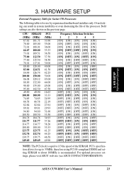
Bold settings are also shown on the previous page. For updated processor settings, please visit ASUS' web site (see ASUS CONTACT INFORMATION) ASUS CUW-RM User's Manual 23 PCI's specification allows for use by experienced motherboard installers only. 3. Overclocking can result in system instability or even shortening the life of the SDRAM. CPU SDRAM (MHz) (MHz) 67... DIMM and setting SDRAM to 1/3 the speed of the processor. HARDWARE SETUP External Frequency Table for Socket 370 Processors The following table is recommended. H/W SETUP Motherboard Settings 3.
Bold settings are also shown on the previous page. For updated processor settings, please visit ASUS' web site (see ASUS CONTACT INFORMATION) ASUS CUW-RM User's Manual 23 PCI's specification allows for use by experienced motherboard installers only. 3. Overclocking can result in system instability or even shortening the life of the SDRAM. CPU SDRAM (MHz) (MHz) 67... DIMM and setting SDRAM to 1/3 the speed of the processor. HARDWARE SETUP External Frequency Table for Socket 370 Processors The following table is recommended. H/W SETUP Motherboard Settings 3.
CUW-RM User Manual
Page 24
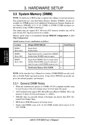
...24 ASUS CUW-RM User's Manual stability. • SDRAM chips are generally thinner with higher pin density than EDO (Extended Data Output) chips. • BIOS shows SDRAM memory on bootup screen. • Single-sided DIMMs come in any combination as Double-Sided registered memory. This motherboard uses...(must be same or half DIMM2 memory size) Total System Memory (Max 512MB) = NOTE: At the time this speed. • ASUS motherboards support SPD (Serial Presence Detect) DIMMs. This is the memory of choice for 3.3Volt (power level) unbuffered Synchronous Dynamic Random Access Memory...
...24 ASUS CUW-RM User's Manual stability. • SDRAM chips are generally thinner with higher pin density than EDO (Extended Data Output) chips. • BIOS shows SDRAM memory on bootup screen. • Single-sided DIMMs come in any combination as Double-Sided registered memory. This motherboard uses...(must be same or half DIMM2 memory size) Total System Memory (Max 512MB) = NOTE: At the time this speed. • ASUS motherboards support SPD (Serial Presence Detect) DIMMs. This is the memory of choice for 3.3Volt (power level) unbuffered Synchronous Dynamic Random Access Memory...
CUW-RM User Manual
Page 25
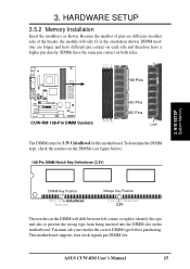
...Reserved 3.3V The notches on the DIMM will only fit in the orientation shown. You must be 3.3V Unbuffered for this motherboard. Because the number of pins are longer and have different pin contact on each side and therefore have the same pin contact ...The DIMMs must ask your retailer the correct DIMM type before purchasing. To determine the DIMM type, check the notches on the motherboard. ASUS CUW-RM User's Manual 25 This motherboard supports four clock signals per DIMM slot. SIMMs have a higher pin density. 3. HARDWARE SETUP 3.5.2 Memory Installation Insert the module...
...Reserved 3.3V The notches on the DIMM will only fit in the orientation shown. You must be 3.3V Unbuffered for this motherboard. Because the number of pins are longer and have different pin contact on each side and therefore have the same pin contact ...The DIMMs must ask your retailer the correct DIMM type before purchasing. To determine the DIMM type, check the notches on the motherboard. ASUS CUW-RM User's Manual 25 This motherboard supports four clock signals per DIMM slot. SIMMs have a higher pin density. 3. HARDWARE SETUP 3.5.2 Memory Installation Insert the module...


